Peter electronic VersiDrive i Series Instruction manual

e l e c t r o n i c
AC Converter
VersiDrive i .../E3S/IP66ODS
Quick Start Manual
Quality is our drive

1
CHECK: Check the correct drive type, check suitable
motor type & info
2
PREPARE: Correct tools, suitable mounting location,
weather protection
3CONNECT: Power & Control connections
4CHECK: Final check of everything before operation
5POWER ON
6COMMISSION the drive parameters
7OPERATE and check everything is as intended
WARNING! The VersiDrive i should ONLY be installed by a qualified electrician.
NOTE This guide does not provide detailed installation, safety or operational instructions.
See the VersiDrive E3S IP66 Outdoor User Manual for complete information.
Unpack and check the drive. Notify the supplier and shipper immediately of any damage.
1CHECK
Identifying the Drive by Model Number
Each drive can be identified by its model number, as shown in the table below. The model number is on the shipping label and
the drive nameplate. The model number includes the drive and any options.
2PREPARE
Prepare the Mounting Location
The VersiDrive must be mounted in a vertical position only.
Installation should be on a suitable flat, flame resistant
surface. Do not mount flammable material close to the
drive.
Refer to Technical Data and ensure the chosen mounting
location is within the drive specification.
The mounting location should be free from vibration.
Do not mount the drive in any area with excessive humidity,
corrosive airborne chemicals or potentially dangerous dust
particles.
Avoid mounting close to high heat sources.
The drive must not be mounted in direct sunlight. If
necessary, install a suitable shade cover.
The mounting location must be free from frost.
Do not restrict the flow of air through the drive heatsink.
The drive generates heat which must be naturally allowed
to dissipate. Correct air clearance around the drive must
be observed.
If the location is subject to wide ambient temperature
and air pressure variation, install a suitable pressure
compensation valve in the drive gland plate.
NOTE If the drive has been in storage for a period longer than 2 years, the DC link capacitors must be reformed. Refer to
online documentation for further information.

3MOUNT
Mechanical Dimensions
Dimensions
Frame
Size
A B C D E Weight
mm in mm in mm in mm in mm in kg Ib
1 232 9,13 161 6,34 162 6,37 189 7,44 148,5 5,85 2,5 5,5
2 257 10,12 188 7,4 182 7,16 200 7,87 176 6,93 3,5 7,7
Mounting Clearance
Drive Size X Above & Below Y Either Side
mm in mm in
All Frame Sizes 200 7.87 10 0.39
NOTE
Typical drive heat losses are approximately 3% of operating load conditions. Above are guidelines only
and the operating ambient temperature of the drive MUST be maintained at all times.
Mounting Bolts & Tightening Torques
Mounting Bolts Tightening Torques
Frame Size Frame Size
Control Terminals
Power Terminals
All Frame Sizes 4 x M4 (#8) All Frame Sizes 0.8 Nm (7 lb-in) 1.5 Nm (13 lb-in)

4CONNECT
Cable Selection
For 1 phase supply (Sizes 1-3 only), the mains power cables should be connected to L1/L, L2/N.
For 3 phase supplies, the mains power cables should be connected to L1, L2, and L3. Phase sequence is not important.
For compliance with CE and C Tick EMC requirements, refer to online documentation.
A fixed installation is required according to IEC61800-5-1 with a suitable disconnecting device installed between the
VersiDrive and the AC Power Source. The disconnecting device must conform to the local safety code / regulations (e.g.
within Europe, EN60204-1, Safety of machinery).
The cables should be dimensioned according to any local codes or regulations. Maximum dimensions are given in the
Rating Tables section of this Quick Start Guide.
Install the Wiring
L1/L L3 EMC
Gland plate
can be removed
for installation
L2/N U V W
1 2 3 4 5 6 7 8 9
10
11
I0I0I I0I0I
Drive Size Cable Gland Sizes
Power Cable Motor Cable Control Cables
1 M20 (PG13.5) M20 (PG13.5) M20 (PG13.5)
2 M25 (PG21) M25 (PG21) M20 (PG13.5)
3 M25 (PG21) M25 (PG21) M20 (PG13.5)
4 M32 (PG29) M32 (PG29) M20 (PG13.5)
Motor Terminal Box
Connections
Most general purpose motors
are wound for operation on dual
voltage supplies. This is indicated
on the nameplate of the motor. This
operational voltage is normally
selected when installing the motor
by selecting either STAR or DELTA
connection. STAR always gives the
higher of the two voltage ratings.
Incoming Supply
Voltage
Motor Nameplate
Voltages Connection
230 230 / 400
Delta
400 400 / 690
400 230 / 400 Star

Information for UL Compliance
VersiDrive E3S is designed to meet the UL requirements. For an up to date list of UL compliant products, please refer to UL
listing NMMS.E226333. In order to ensure full compliance, the following must be fully observed.
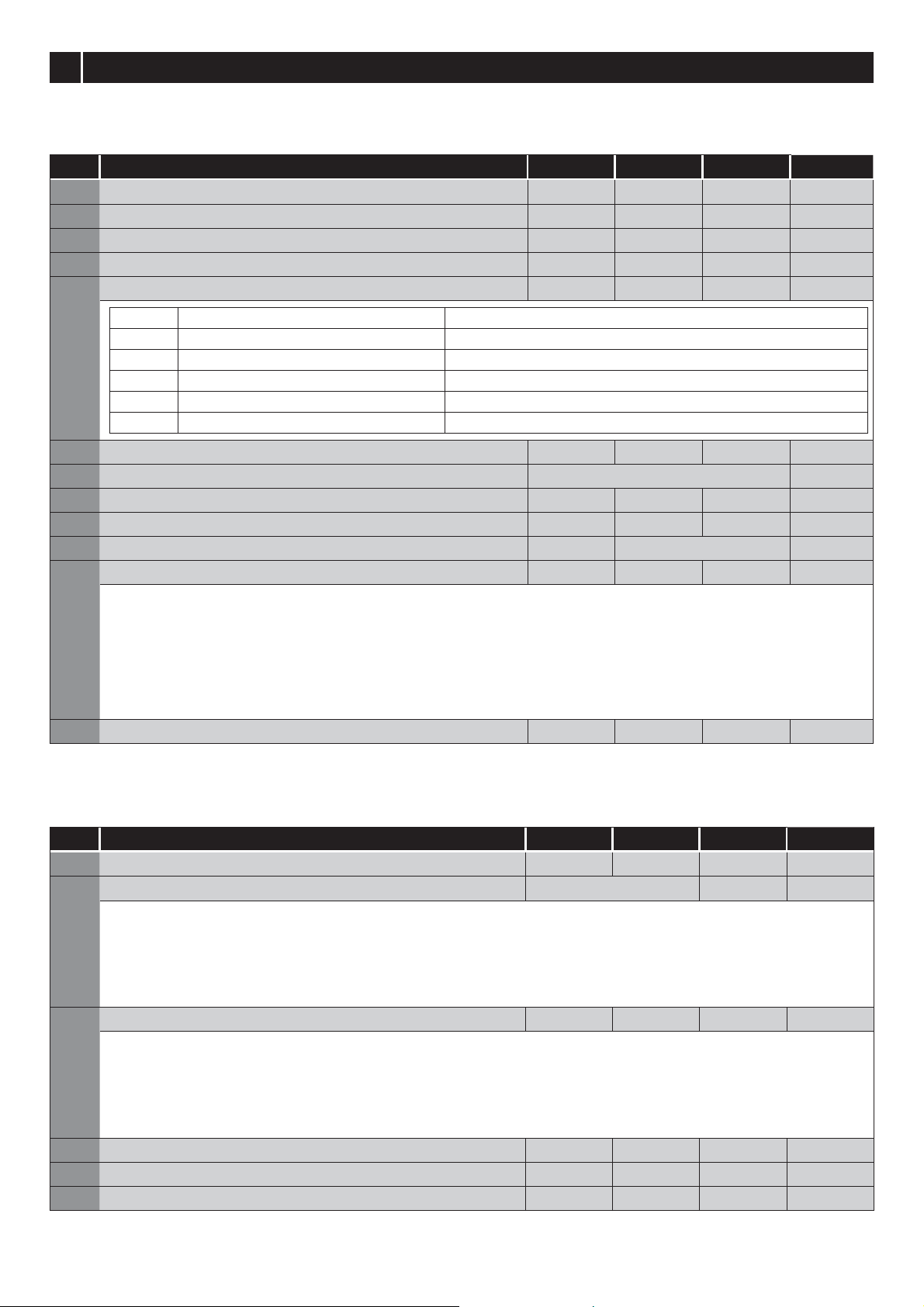
Input Power Supply Requirements
Supply Voltage 200 – 240 RMS Volts for 230 Volt rated units, + /- 10% variation allowed. 240 Volt RMS Maximum.
380 – 480 Volts for 400 Volt rated units, + / - 10% variation allowed, Maximum 500 Volts RMS.
Frequency 50 – 60Hz + / - 5% Variation
Short Circuit
Capacity
All drives are suitable for use on a circuit capable of delivering not more than 100kA maximum short-
circuit Amperes symmetrical with the specified maximum supply voltage when protected by Class J fuses.
Mechanical Installation Requirements
All VersiDrive E3S units are intended for installation within controlled environments which meet the condition limits shown in
the Environment section of this Quick Start Guide.
The drive can be operated within an ambient temperature range as stated in the Environment section of this Quick Start Guide.
For IP66 (Nema 4X) units, installation in a pollution degree 2 environment is permissible.
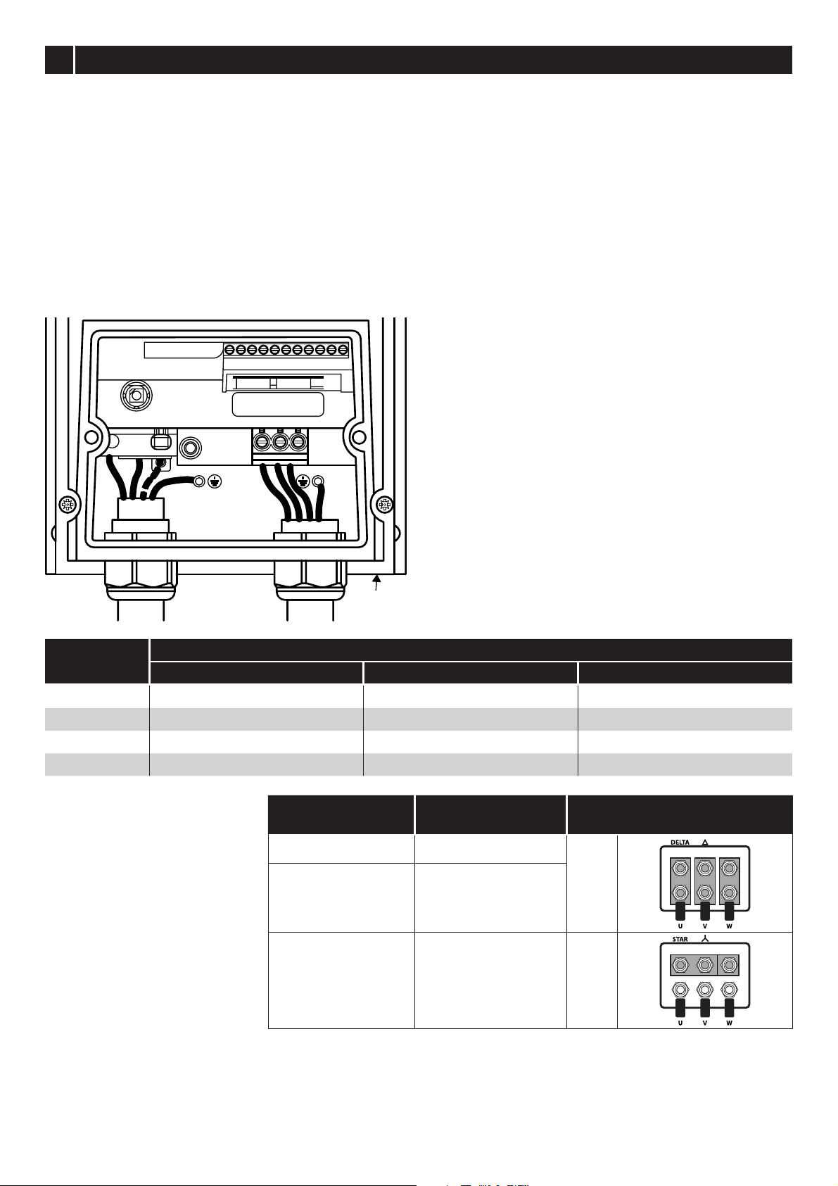
Electrical Installation Requirements
Incoming power supply connection must be according to the Install the Wiring section of this Quick Start Guide.
Suitable power and motor cables should be selected according to the data shown in Rating Tables section of this Quick
Start Guide and the National Electrical Code or other applicable local codes.
Motor Cable 75°C Copper must be used.
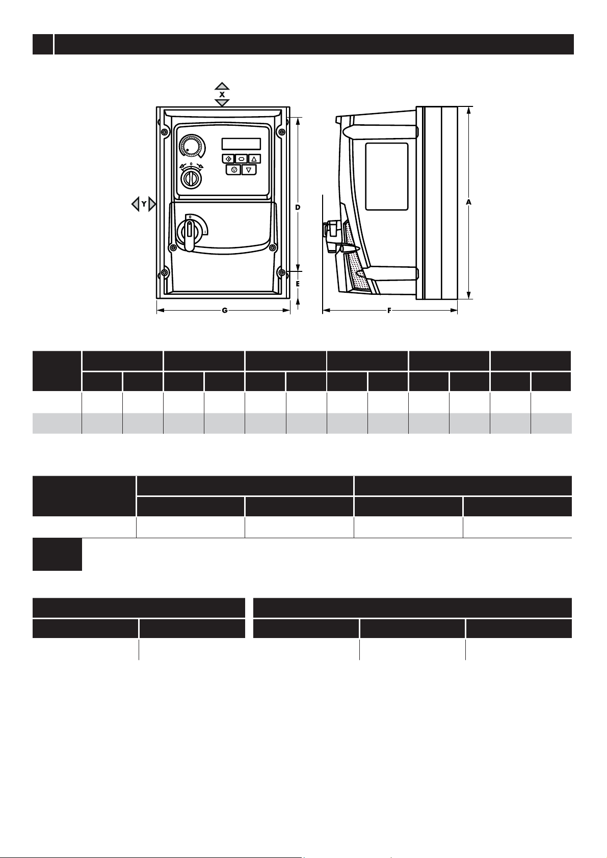
Power cable connections and tightening torques are shown in the Mechanical Dimensions section of this Quick Start Guide.
Integral Solid Sate short circuit protection does not provide branch circuit protection. Branch circuit protection must be
provided in accordance with the national electrical code and any additional local codes. Ratings are shown in the Rating
Tables section of this Quick Start Guide.
For Canadian installations transient surge suppression must be installed on the line side of this equipment and shall be rated
480Volt (phase to ground), 480 Volt (phase to phase), suitable for over voltage category iii and shall provide protection for
a rated impulse withstand voltage peak of 2.5kV.
UL Listed ring terminals / lugs must be used for all bus bar and grounding connections.
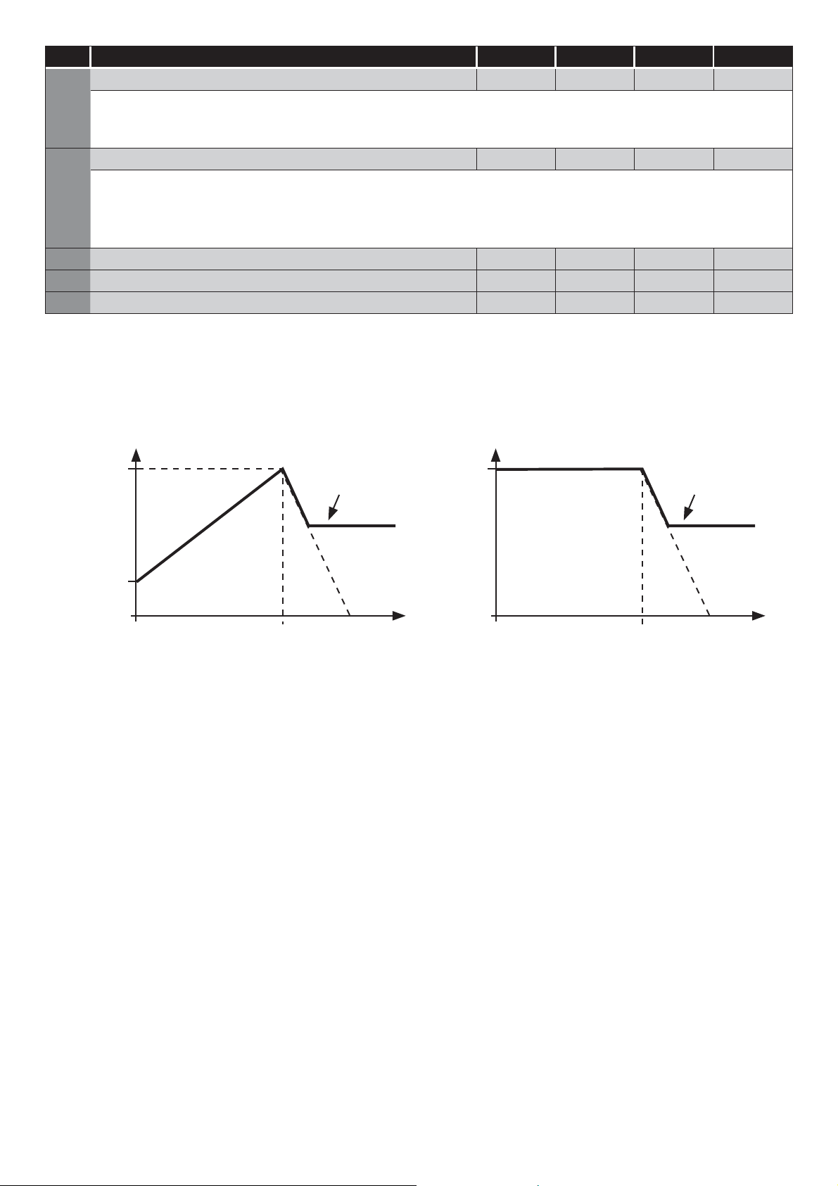
General Requirements
VersiDrive E3S provides motor overload protection, set at 150% of full load, in accordance with the National Electrical Code
(US).
Where a motor thermistor is not fitted, or not utilised, Thermal Overload Memory Retention must be enabled by setting P-60 = 1.
Where a motor thermistor is fitted and connected to the drive, connection must be carried out according to the information
shown in the Motor Thermistor Connection section of the Quick Start Guide.
UL rated ingress protection (“Type” ) is only met when cables are installed using a UL recognized bushing or fitting for a
flexible conduit system which meets the required level of protection (“Type”).
For conduit installations the conduit entry holes require standard opening to the required sizes specified per the NEC.
Not intended for installation using rigid conduit system.
WARNING: The opening of the branch-circuit protective device may be an indication that a fault has been interrupted. To reduce
the risk of fire or electric shock, current-carrying parts and other components of the controller should be examined and replaced if
damaged. If burnout of the current element of an overload relay occurs, the complete overload relay must be replaced.
Control Terminal Wiring
All analog signal cables should be suitably shielded.
Twisted pair cables are recommended.
Power and Control Signal cables should be routed
separately where possible, and must not be routed parallel
to each other.
Signal levels of different voltages e.g. 24 Volt DC and 110
Volt AC, should not be routed in the same cable.
Maximum control terminal tightening torque is 0.5Nm.
Control Cable entry conductor size: 0.05 – 2.5mm2 /
30 – 12 AWG.
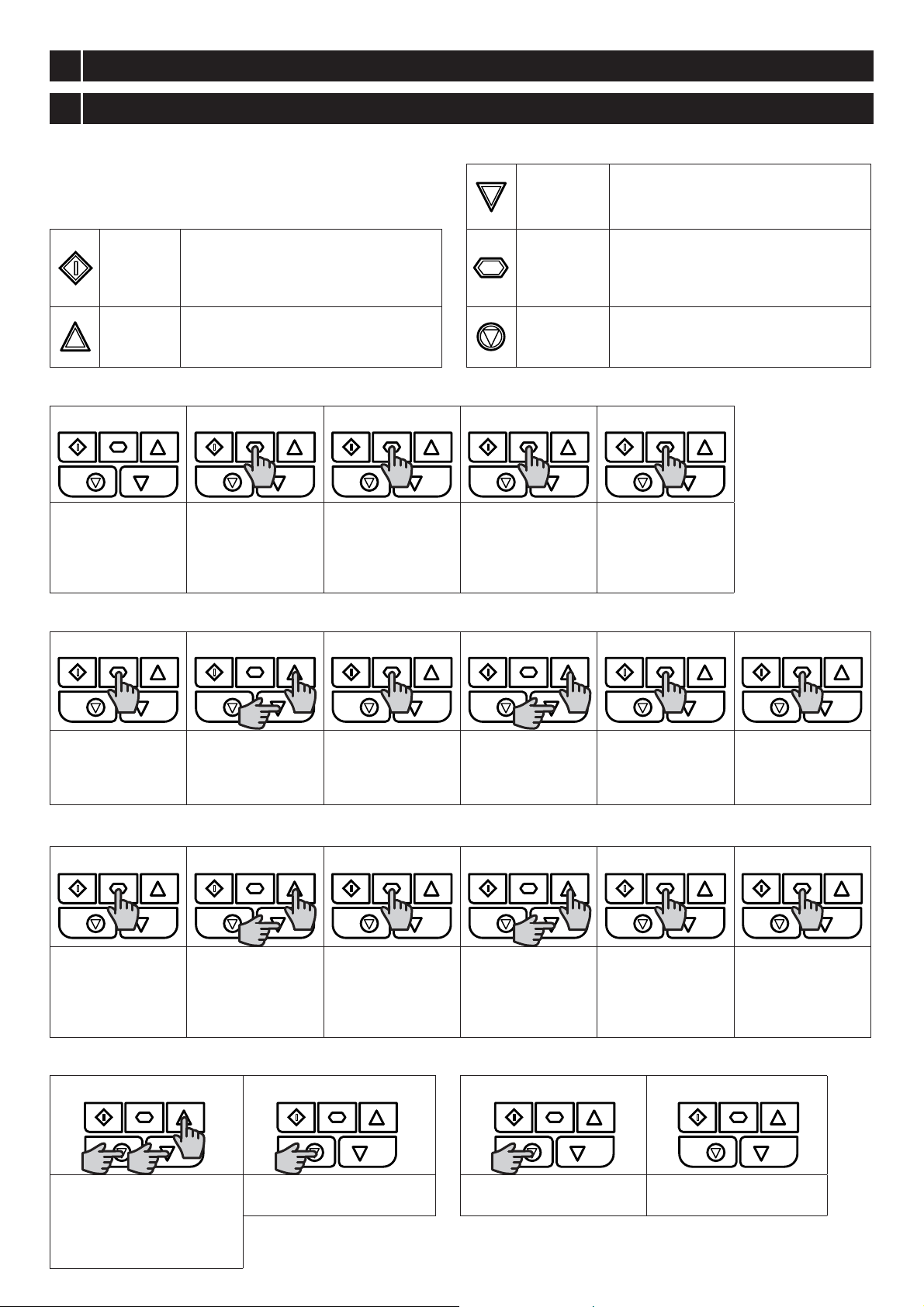
Control Terminal Connections
Switched Units: May use the built in control switch and
potentiometer, or external control signals connected to the
control terminals.
Non-Switched Units: Require external control signals to
be connected to the control terminals.

Switched Units: Default functions of the control switches
Switch Position POT Notes
Factory Default
Configuration.
Run Forward or Reverse
with speed controlled from
the Local POT.
Run Reverse
STOP
Run Forward Sets the output frequency
NOTE Other functions are possible, please refer to the online documentation for additional information.
Using the Control Terminals
Connection Example
Factory Default Functions
No.
Description
DI1 0/1 Open : Stop Closed : Run
DI2 3/4Open : Forward Rotation Closed : Reverse Rotation
DI3 Analog Speed Reference /
Preset Speed
Open : Speed Reference set by Analog Speed Reference
Closed : Speed Reference set by Preset Speed 1 (P-20)
AI1 Analog Speed Reference
Input
Sets the Speed Reference
NOTE For Switched units, the internal pot is selected by default in P-16.
For Non-switched units, an external pot or 0 - 10 V reference may be connected. Other
signal types may also be used, set P-16 to the correct format.
NOTE
Additional functions are possible, refer to the online documentation for further information.
Motor Thermistor Connection
Where a motor thermistor is to be used, it should be connected as follows:
Control Terminal Strip Additional Information
Compatible Thermistor: PTC Type, 2.5kΩ trip level.
Use a setting of P-15 that has Input 3 function as External Trip,
e.g. P-15 = 3. Refer to online documentation for further details.
Set P-47 = “SWFWK"
5CHECK
+24
VDC DI1 DI2 DI3
AI2
+10
VDC
DI4
AI1 0V A0 0V RL1 RL2
Nr. Purpose Function
1 +24 VDC 100 mA Output 24 VDC Output
2 DI1 Digital Input 1 Function defined by
P-12 & P-15.
See below for futher info
3 DI2 Digital Input 2
4 DI3 Digital Input 3/AI2 Analog Input 2
5 +10 VDC 10 mA Output 10 VDC Output for external potentiometer
6 DI4 Digital Input 4/AI1 Analog Input 1 Function defined in P-12 & P-15. Signal format selected in P-16
7 0 VDC Common
8 AO Analog Output/Digital Output Funktion selected in P-25. See Parameter list
9 0 VDC Common
10 RL1 Output Relay Function defined in P-18. See Parameter list
11 RL2 Output Relay

6POWER ON
7COMMISSION
Operation
Managing the Keypad
The drive is configured and its operation monitored via the
keypad and display. DOWN
Used to decrease speed in real-time
mode or to decrease parameter values
in parameter edit mode.
START
When in keypad mode, used to Start a
stopped drive or to reverse the direction
of rotation if bi-directional keypad
mode is enabled.
NAVIGATE
Used to display real-time information,
to access and exit parameter edit mode
and to store parameter changes.
UP
Used to increase speed in real-time
mode or to increase parameter values
in parameter edit mode.
RESET /
STOP
Used to reset a tripped drive.
When in Keypad mode is used to Stop
a running drive.
Operating Displays
67R3 + $ 3
Drive Stopped /
Disabled
Drive is enabled
/ running, display
shows the output
frequency (Hz)
Press the Navigate
key for < 1 second.
The display will
show the motor
current (Amps)
Press the Navigate
key for < 1 second.
The display will
show the motor
power (kW)
If P-10 > 0, pressing
the
Navigate key
for < 1 second will
display the motor
speed (RPM)
Changing Parameters
67R3 3 3 3 3
Press and hold the
Navigate key > 2
seconds
Use the up and
down keys to
select the required
parameter
Press the Navigate
key for < 1 second
Adjust the value
using the Up and
Down keys
Press for < 1 second
to return to the
parameter menu
Press for > 2
seconds to return
to the operating
display
Read Only Parameter Access
67R3 3 3 3 67R3
Press and hold the
Navigate key > 2
seconds
Use the up and
down keys to select
P-00
Press the Navigate
key for < 1 second
Use the up and
down keys to select
the required Read
Only parameter
Press the Navigate
key for < 1 second
to display the value
Press and hold the
Navigate key > 2
seconds to return
to the operating
display
Resetting Parameters
3GHI 67R3
To reset parameter values to
their factory default settings,
press and hold Up, Down and
Stop buttons for > 2 seconds.
The display will show “SGHI”
Press the Stop key. The
display will show “VWRS”
Resetting a Fault
2, 67R3
Press the Stop key. The
display will show “VWRS”

8OPERATE
Parameters
Standard Parameters
Par. Description Min
Max
Default Units
P-01
Maximum Frequency/Speed Limit
P-02 500.0 50.0 (60.0) Hz/RPM
P-02 Minimum Frequency/Speed Limit 0.0 P-01 0.0 Hz/RPM
P-03 Acceleration Ramp Time 0.00 600.0 5.0 s
P-04 Deceleration Ramp Time 0.00 600.0 5.0 s
P-05 Stopping Mode/Mains Loss Response 0 4 0 -
Setting On Disable On Mains Loss
0 Ramp to Stop (P-04)
Ride Through (Recover energy from load to maintain operation)
1 Coast Coast
2 Ramp to Stop (P-04) Fast Ramp to Stop (P-24), Coast if P-24 = 0
3
Ramp to Stop (P-04) with AC Flux Braking
Fast Ramp to Stop (P-24), Coast if P-24 = 0
4
Ramp to Stop (P-04)
No action
P-07
Motor Rated Voltage/Back
EMF at rated speed (PM/BLDC)
0 250/ 500 230/400 V
P-08 Motor Rated Current
Drive Rating Dependent
A
P-09 Motor Rated Frequency 10 500 50 (60) Hz
P-10 Motor Rated Speed 0 30000 0 RPM
P-11
Low Frequency Torque Boost
0.0
Drive Dependent
%
P-12 Primary Command Source 0 9 0 -
0: Terminal Control
1: Uni-directional Keypad Control
2: Bi-directional Keypad Control
3: Modbus Network Control
4: Modbus Network Control
5: PI Control
6: PI Analog Summation Control
7: CAN Control
8: CAN Control
9: Slave Mode
NOTE When P-12 = 1, 2, 3, 4, 7, 8 or 9, an enable signal must still be provided at the control terminals, digital input 1.
P-14
Extended Menu Access code
0 65535 0 -
Extended Parameters
Par. Description Min
Max
Default Units
P-15
Digital Input Function Select
0 17 0 -
P-16 Analog Input 1 Signal Format See Below U0-10 -
8 : Unidirectional, External 0 – 10Volt reference / pot
% : Bi-directional, External 0 – 10Volt reference / pot
$ : External 0 – 20mA signal
W : External 4-20mA signal, trip on loss
U : External 4 – 20mA signal
W : External 20 – 4mA signal, trip on loss
U : External 20 – 4mA signal
8 : External 10 – 0 Volt signal
,QSRW : Switched units only : Internal pot
P-18 Output Relay Function Select 0 9 1 -
0: Drive Enabled (Running)
1: Drive Healthy
2: At Target Frequency (Speed)
3: Drive Tripped
4: Output Frequency >= Limit
5: Output Current >= Limit
6: Output Frequency < Limit
7: Output Current < Limit
8: Analog Input 2 > Limit
9: Drive Ready to Run
P-20
Preset Frequency / Speed 1
-P-01 P-01 5.0 Hz/RPM
P-21
Preset Frequency / Speed 2
-P-01 P-01 25.0 Hz/RPM
P-22
Preset Frequency / Speed 3
-P-01 P-01 40.0 Hz/RPM

Par. Description Min
Max
Default Units
P-23
Preset Frequency / Speed 4
-P-01 P-01 P-09 Hz/RPM
P-24 2nd Ramp Time (Fast Stop) 0.00 600.0 0.00 s
P-25 Analog Output Function Select 0
11 8
-
Digital Output Mode. Logic 1 = +24V DC Analog Output Mode
0: Drive Enabled (Running)
1: Drive Healthy
2: At Target Frequency (Speed)
3: Drive Tripped
4: Output Frequency >= Limit
5: Output Current >= Limit
6: Output Frequency < Limit
7: Output Current < Limit
8: Output Frequency (Motor Speed)
9: Output (Motor) Current
10: Output Power
11: Load Current
P-30 Start/ Restart/ Fire Mode Configuration
Index 1: Start Mode / Auto Restart N/A N/A Edge-r -
(GJHU: Following Power on or reset, the drive will not start if Digital Input 1 remains closed. The Input must be closed after a power
on or reset to start the drive.
$XWR: Following a Power On or Reset, the drive will automatically start if Digital Input 1 is closed.
$XWR To $XWR: Following a trip, the drive will make up to 5 attempts to restart at 20 second intervals.
Index 2: Fire Mode Input Logic 0 1 0 -
0: Normally Closed (NC) input. Fire Mode active if input is open.
1: Normally Open (NO) input. Fire Mode active if input is closed.
Index 3: Fire Mode Input Latch 0 1 0 -
0: Latched input. The drive will remain in Fire Mode, only as long the fire mode input signal remains
(Normally Open or Normally Closed operation is supported depending on Index 2 setting).
1: Momentary input. Fire Mode is activated by a momentary signal on the input. Normally Open or Normally Closed
operation is supported depending on Index 2 setting. The drive will remain in Fire Mode until disabled or powered off.
P-31 Keypad Start Mode Select 0 7 1 -
0: Minimum Speed, Keypad Start
1: Previous Speed, Keypad Start
2: Minimum Speed, Terminal Enable
3: Previous Speed, Terminal Enable
4: Current Speed, Keypad Start
5: Preset Speed 4, Keypad Start
6: Current Speed, Terminal Start
7: Preset Speed 4, Terminal Start
P-32 Starting Boost Frequency 0 P-09 P-09 Hz
Sets the frequency used during the starting boost phase of operation refer to section 6.4 for further information.
P-33 Boost Period Duration 0 150 5 s
Time for which the start-up boost period is applied. During this period, the output frequency is set to P-32 and the voltage increases
linearly from P-11 to P-07. Setting P-33 to zero disables boost. See section 6.4 for additional information.
P-34 Brake Chopper Enable (Not Size 1) 0 4 0 -
0: Disabled
1: Enabled With Software Protection
2: Enabled Without Software Protection
3: Enabled With Software Protection
4: Enabled Without Software Protection
P-38 Parameter Access Lock 0 1 0 -
0: Unlocked 1: Locked
P-39 Analog Input 1 Offset
-500.0
500.0 0.0 %
P-40
Index 1: Display Scaling Factor
0.000 16.000 0.000 -
Index 2: Display Scaling Source
0 3 0 -
P-41
PI Controller Proportional Gain
0.0 30.0 1.0 -
P-42 PI Controller Integral Time 0.0 30.0 1.0 s
P-43 PI Controller Operating Mode 0 3 0 -
0: Direct Operation
1: Inverse Operation
2: Direct Operation, Wake at Full Speed
3: Reverse Operation, Wake at Full Speed
P-44 PI Reference (Setpoint) Source Select 0 1 0 -
0: Digital Preset Setpoint 1: Analog Input 1 Setpoint
P-45 PI Digital Setpoint 0.0 100.0 0.0 %

Par. Description Min
Max
Default Units
P-46 PI Feedback Source Select 0 5 0 -
0: Analog Input 2
1: Analog Input 1
2: Motor Current
3: DC Bus Voltage
4: Analog 1 – Analog 2
5: Largest (Analog 1, Analog 2)
P-47 Analog Input 2 Signal Format - - - U0-10
8 : Unidirectional, External 0 – 10Volt reference / pot
$ : External 0 – 20mA signal
W : External 4-20mA signal, trip on loss
U : External 4 – 20mA signal
W : External 20 – 4mA signal, trip on loss
U : External 20 – 4mA signal
SWFWK : Motor thermistor
P-48 Standby Mode Timer 0.0 25.0 0.0 s
P-49
PI Control Wake Up Error Level
0.0 100.0 5.0 %
P-50 User Output Relay Hysteresis 0.0 100.0 0.0 %
Single Phase Motor - Boost Starting cycle
In order to provide a reliable method for starting the motor, a special technique is used. The motor is started immediately at rated frequency,
whilst the voltage is ramped from an initial Boost Voltage (set in P-11) to the Motor Rated Voltage (set in P-07) over a Boost Period Duration
(set in P-33). Following the starting boost period, the drive then begins to control the output frequency and speed of the motor. The graphs
below show how this operation works.
Voltage
P-07
P-11
Time (s)
P-33 P-04
Requested
Speed
Frequency
P-32
P-33 P-04
Requested
Speed
In order to achieve reliable starting and optimise the starting method, the following procedure can be used.
1.The motor must be correctly connected to the drive and safe to operate before using this procedure.
2.Ensure the motor rated voltage (P-07) and current (P-08) have been correctly programmed in the drive parameters.
3.Select Extended Parameter Access by setting P-14 = 101.
4.Set the Boost Period Duration P-33 to the maximum allowed value of 150 seconds.
5.
Start the drive, and display the motor current (press the Navigate button until the display shows “$x.x” where x is the motor
current).
6.
Check the current value compared to the motor rated current around 3 – 5 seconds after starting the drive
a. If the current displayed is less than 80% of the motor rated current
o Stop the drive
o Increase P-11
o Repeat from step 5
b. If the current displayed is greater than 90% of the motor rated current
o Stop the drive
o Reduce P-11
o Repeat from step 5
7.The correct boost voltage setting should deliver 80 – 90% of the motor rated current approximately 3 – 5 seconds after
enabling the drive.
8.Now the boost Period Duration may be reduced to match the actual time required for the motor to start. The simplest
method is to initially reduce in large steps and monitot the motor behaviour on starting the drive. The ideal boost period will
be a few seconds longer than is required to bring the motor to full speed.
By following this procedure, the motor starting parameter can be optimised to start the motor reliably without excessive starting
current.

Technical Data
Environment
Operational ambient temperature range
Enclosed Drives: -20 ... 40°C (frost and condensation free)
Storage ambient temperature range: -40 … 60°C
Maximum altitude: 2000m. Derate above 1000m: 1% / 100m
Maximum humidity: 95%, non-condensing
Rating Tables
Frame
Size
kW HP
Input
Current
Fuse/MCB
(Typ B)
Maximum Cable
Size
Output
Current
Recommended
Brake Resistance
Non UL UL mm AWG A Ω
110 - 115 (+ / - 10%) V 1 Phase Input, 3 Phase Output
1 0,37 0,5 8,5 16 15 8 8 7,0 -
2 0,75 1 12,5 16 15 8 8 10,5 100
200 - 240 (+ / - 10%) V 1 Phase Input, 3 Phase Output
1 0,37 0,5 6,0 10 10 8 8 4,3 -
1 0,75 1 9,3 16 15 8 8 7,0 -
1 1,1 1,5 14,0 20 20 8 8 10,5 100
NOTE Cable sizes shown are the maximum possible that may be connected to the drive. Cables should be selected
according to local wiring codes or regulations at the point of installation.

Troubleshooting
Fault Code Messages
Fault Code
No.
Description
2,E 01 Brake channel over current
2/EU 02 Brake resistor overload
2, 03 Output Over Current
,WWUS
04
Motor Thermal Overload (I2t)
29ROW 06 Over voltage on DC bus
89ROW 07 Under voltage on DC bus
2W 08 Heatsink over temperature
8W 09 Under temperature
(WULS 11 External trip
6&2E6 12 Optibus comms loss
)/WGF 13 DC bus ripple too high
3/266 14 Input phase loss trip
K 2, 15 Output Over Current
WK)OW 16
Faulty thermistor on heatsink
G$W$) 17
Internal memory fault (IO)
) 18 4-20mA Signal Lost
G$W$( 19
Internal memory fault (DSP)
)3WF 21 Motor PTC thermistor trip
)$1) 22
Cooling Fan Fault (IP66 only)
2K($W 23
Drive internal temperature too high
287) 26 Output Fault
$W) 41 Autotune Fault
6&) 50 Modbus comms loss fault
6&) 51 CAN comms loss trip
NOTE Following an over current or overload trip (1, 3, 4, 15), the drive may not be reset until the reset time delay has elapsed
to prevent damage to the drive.

Phone: +49(0)9189/4147-0 Fax: +49(0)9189/4147-47 eMail: mail@peter-electronic.com
PETER electronic GmbH & Co. KG Bruckäcker 9 D-92348 Berg www.peter-electronic.com
This manual suits for next models
3
Table of contents
Popular Media Converter manuals by other brands

Extron electronics
Extron electronics Two InpuT VIdeo Scaler IN1502 Specifications

Monoprice
Monoprice Blackbird 15259 user manual

Microchip Technology
Microchip Technology TC110 user guide

Advanced
Advanced Axis AX AV-V70 Installation, operation, & programming manual

ExpertDAQ
ExpertDAQ EX9486C-W Operation manual

J-Tech Digital
J-Tech Digital JTD-220 Setup guide