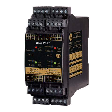
Advanced Axis AX AV-V70 Owner's manual

www.advancedco.com
AV-V70
Universal Audio Converter
Installation, Operation & Programming Manual

www.advancedco.com
2
Table of Contents Page
1INTRODUCTION...................................................................................................................................................3
2GENERAL INSTALLATION NOTES....................................................................................................................4
3AV-V70 ENCLOSURE MOUNTING.....................................................................................................................4
425VRMS “HOST” SPEAKER CIRCUIT WIRING.................................................................................................5
524 VDC POWER WIRING.....................................................................................................................................6
670VRMS SPEAKER CIRCUIT WIRING...............................................................................................................7
7PREWIRED AUDIO CONVERTER TRANSFORMER AND LED INDICATOR CARD........................................8
870VRMS SPEAKER CIRCUIT INTERFACE CARD AND AUDIO CONVERTER TRANSFORMER
EXPANSION..................................................................................................................................................................9
A.INSTALLING THE ADDITIONAL AUDIO CONVERTER TRANSFORMER .......................................................9
B.INSTALLING THE ADDITIONAL 70VRMS SPEAKER CIRCUIT INTERFACE CARD......................................9
9MODULE SPECIFICATIONS .............................................................................................................................11

www.advancedco.com
www.advancedco.com 3
1 Introduction
The Advanced AV-V70 is a universal audio converter that converts any ANSI/UL Listed, maximum 40 Watt, 25Vrms
speaker circuit to a 40 Watt 70Vrms speaker circuit. The AV-V70 includes a 70Vrms Speaker Circuit Interface Card,
an Audio Converter Transformer, an LED Indicator Card and an enclosure. Each AV-V70 enclosure is capable of
supporting two (2) 70Vrms Speaker Circuit Interface Cards and Audio Converter Transformers. In addition to getting
wired to an existing speaker circuit, each 70Vrms Speaker Circuit Interface Card requires power from either the
“Host” fire alarm control panel or from an ANSI/UL Listed 24 VDC nominal power supply.
Note: The power supply power to the AV-V70 70Vrms Speaker Circuit Interface Card must be a 24 VDC
ANSI/UL Listed, regulated and power-limited supply.
Figure 1 – AV-V70 (shown with two (2) 70Vrms Speaker Circuit Interface Cards and Audio Converter Transformers)
Figure 2 – AV-V70 (bottom view with two (2) stacked 70Vrms Speaker Circuit Interface Cards)

www.advancedco.com
4
2 General Installation Notes
WARNING: Disconnect all sources of power
before installing or servicing the AV-V70.
DO NOT install/remove circuit cards or
transformers while the AV-V70 is supplied with
power.
ENVIRONMENT: INSTALL the equipment in a
clean, dry environment.
The equipment meets the requirements for
operation at 32°F - 120°F (0°C - 49°C) and relative
humidity of 85% RH.
WIRING: CHECK that the installation wire sizes
are adequate to deliver the required load current
and maintain compatibility with the specific device
operating voltages.
USE an anti-static wrist strap
whenever handling circuit cards.
STORE circuit cards in static
suppressive packaging.
A secure dedicated ground connection is
required. Although no system is immune
to the effects of lightning strikes, a
secure ground connection will reduce
susceptibility. The use of overhead or
outside aerial wiring is not
recommended.
3 AV-V70 Enclosure Mounting
When mounting the AV-V70 enclosure, ensure that there is sufficient space to allow the cover to be opened /
removed after installation. If the cover is completely removed remember to reconnect the earth/ground wire when
reinstalling. The AV-V70 universal audio converter panel enclosure is designed for surface mounting.
There are three (3) mounting holes located on the back wall of the AV-V70 enclosure/back box (see figure 3). The
top center mounting hole is keyed for ease of mounting. Place the back box on the wall and mark the top center
keyed mounting hole. Drill the marked location and partially install the mounting screw in the wall.
Hang the enclosure on the center mounting screw. Level the enclosure and mark the remaining two mounting holes
(on the bottom). Drill the remaining holes and insert all screws and firmly tighten.
Caution: If drilling while mounting the AV-V70 enclosure is going to make any metal filings or other PC
board contaminants, remove all circuit cards from the enclosure.
Must be
Grounded
ATTENTION
OBSERVE PRECAUTIONS
FOR HANDLING
ELECTROSTATIC
SENSITIVE DEVICES

www.advancedco.com
www.advancedco.com 5
Note: Failure to ground the AV-V70 enclosure or to tighten screws associated with PCB boards will defeat
the protection circuitry designed to protect the modules/cards from damage due to lightning and static
electricity.
4 25Vrms “Host” Speaker Circuit Wiring
The AV-V70 includes one 70Vrms Speaker Circuit Interface Card prewired to an installed Audio Converter
Transformer and LED Indicator Card. Whether the “Host” speaker circuit is wired Class A or B, run the existing
25Vrms (40 Watt maximum) speaker circuit wiring to the 25V Audio Input terminals (B+, B-) of the 70Vrms Speaker
Circuit Interface Card. If the “Host” speaker circuit is wired Class B, install the “Host” panel’s speaker circuit end-of-
line (EOL) resistor across the 25V Audio Input terminals A- and A+ of the 70Vrms Speaker Circuit Interface Card
(see figure 4). If the “Host” speaker circuit is wired Class A, instead of placing the “Host” panels speaker circuit end-
of-line (EOL) across the A- and A+ terminals, connect the return “Host” panel’s Class A speaker circuit wiring to
these terminals (see figure 5).
9"
11 7/8"
1 1/8"
4 1/2”
10 3/4"
4 1/4” 7 3/4” 3"
Grounding Screw
Figure 3 – AV-V70 Enclosure Dimensions and Mounting

www.advancedco.com
6
5 24 VDC Power Wiring
The 70Vrms Speaker Circuit Interface Card requires 24 VDC regulated and power-limited power from the “Host” fire
alarm control panel or from an ANSI/UL Listed power supply. Wire 24 VDC from the “Host” fire alarm control panel
or an ANSI/UL Listed power supply to terminals 0V and +24V of the 70Vrms Speaker Circuit Interface Card [0V =
negative, +24V = positive] (see figure 6).
Note: The power supply power to the 70Vrms Speaker Circuit Interface Card must be a 24 VDC ANSI/UL
Listed, regulated and power-limited supply.
Figure 4 – 70Vrms Speaker Circuit Interface Card, “Host” Class B Speaker Circuit Wiring
Figure 5 – 70Vrms Speaker Circuit Interface Card, “Host” Class A Speaker Circuit Wiring

www.advancedco.com
www.advancedco.com 7
6 70Vrms Speaker Circuit Wiring
The 70Vrms Speaker Circuit Interface Card can be wired to the 70Vrms speakers either via Class A or Class B
wiring. If wiring Class B, set 70Vrms speaker circuit output style wiring jumper to B, and wire terminals B+ and B- of
the 70Vrms Speaker Circuit Interface Card to each speaker, terminating the wiring with a 100K end-of-line resistor
[EOL] (see figure 7).
If wiring Class A, set 70Vrms speaker circuit output style wiring jumper to A, and wire terminals B+ and B- of the
70Vrms Speaker Circuit Interface Card to each speaker and return the B+ wire to terminal A+ and the B- terminal to
terminal A- on the 70Vrms Speaker Circuit Interface Card (see figure 8).
Figure 6 – 70Vrms Speaker Circuit Interface Card 24 VDC Wiring
Figure 7 – 70Vrms Speaker Circuit Interface Card 70Vrms Class B Wiring

www.advancedco.com
8
7 Prewired Audio Converter Transformer and LED Indicator Card
As previously indicated, the AV-V70 includes an installed 70Vrms Speaker Circuit Interface Card prewired to the
Audio Converter Transformer and the LED Indicator Card. Wiring to the Audio Converter Transformer includes both
the 25Vrms input wiring and the 70Vrms output wiring (see figure 9).
In addition to the Audio Converter Transformer wiring, the 70Vrms Speaker Circuit Interface Card is prewired to an
LED Indicator Card, located on the front of the AV-V70 enclosure. The LED Indicator Card includes a 24 VDC LED
and 70Vrms Speaker Circuit Interface Card trouble LED (see figure 10).
A+ A- B- B+
OUTPUT AUDIO 70V 70V 70V NC 25V 25V
AUDIO TRANSFORMER
+24 0 +24 0
V V V V N/O COM B+ B- A- A+
J1
A
B
OUTPUT
STYLE
REMOTE LED
CONNECTIONS
POWER
TROUBLE
TROUBLE 25V AUDIO INPUT
Upper Transformer
Wiring (25Vrms)
Lower Transformer
Wiring (70Vrms)
Figure 8 – 70Vrms Speaker Circuit Interface Card 70Vrms Class A Wiring
Figure 9 – 70Vrms Speaker Circuit Interface Card Wiring to Audio Converter Transformer

www.advancedco.com
www.advancedco.com 9
8 70Vrms Speaker Circuit Interface Card and Audio Converter
Transformer Expansion
As previously indicated, the AV-V70 universal audio converter is capable of supporting two (2) 70Vrms Speaker
Circuit Interface Cards and Audio Converter Transformers. Adding an additional 70Vrms Speaker Circuit Interface
Card and Audio Converter Transformer requires acquiring and installing an AV-V70-KIT.
An AV-V70-KIT includes the following:
One (1) 70Vrms Speaker Circuit Interface Card
One (1) Audio Converter Transformer
One (1) Panel Status Interconnect Cable
One (1) Hardware Packet
(4 standoffs, 4 spare screws, 2 washers, 2 lock washers and 2 nuts)
One (1) Installation Instruction
a. Installing the Additional Audio Converter Transformer
To install the AV-V70-KIT Audio Converter Transformer (XFRM #2), place the new transformer over the studs
above the original AV-V70 Audio Converter Transformer (XFRM #1). Place the provided washer and lock washer
over each stud and secure with the provided nuts (see figure 11).
b. Installing the Additional 70Vrms Speaker Circuit Interface Card
Remove the four screws securing the original AV-V70 70Vrms Speaker Circuit Interface Card and replace with the
provided four standoffs. Secure the new 70Vrms Speaker Circuit Interface Card to the installed four standoffs, with
the four previously removed screws (see figure 11).
Wire the black wires attached to the newly installed Audio Converter Transformer (XFRM #2) to the Audio
Transformer 25V terminals located on the newly installed 70Vrms Speaker Circuit Interface Card. Wire the red wires
attached to the newly installed Audio Converter Transformer (XFRM #2) to the Audio Transformer 70V terminals
located on the newly installed 70Vrms Speaker Circuit Interface Card (see figure 11).
Connect the black end of the two pin cable assembly provided with the AV-V70-KIT to the two pins labeled Remote
LED Connections Trouble, located on the newly installed 70Vrms Speaker Circuit Interface Card. As this is not a
keyed connection, ensure the black wire of the two pin cable is installed on the K pin of the 70Vrms Speaker Circuit
Interface Card. Connect the other end (white) of the two pin cable to the Trbl #2 LED Drive connector located on the
Figure 10 – 70Vrms Speaker Circuit Interface Card Wiring to LED Indicator Card

www.advancedco.com
10
LED Indicator Card, installed on the AV-V70 enclosure door, this is a keyed connection and can only be installed
one way (see figure 11).
Wire 24VDC regulated and power-limited power from the “Host” fire alarm control panel or from an ANSI/UL Listed
power supply to terminals 0V and +24V of the newly installed 70Vrms Speaker Circuit Interface Card [0V =
negative, +24V = positive]. Wire from the newly installed 70Vrms Speaker Circuit Interface Card terminals 0V and
+24V [0V = negative, +24V = positive] to the bottom of the original installed AV-V70, 70Vrms Speaker Circuit
Interface Card [0V = negative, +24V = positive] (see figure 11).
Note: For “Host” panel 25Vrms speaker circuit wiring and 70Vrms speaker circuit wiring refer to the
appropriate sections of this document.
A+ A- B- B+
OUTPUT AUDIO 70V 70V 70V NC 25V 25V
AUDIO TRANSFORMER
+24 0 +24 0
V V V V N/O COM B+ B- A- A+
J1
A
B
OUTPUT
STYLE
REMOTE LED
CONNECTIONS
POWER
TROUBLE
TROUBLE 25V AUDIO INPUT
Existing Power LED Drive
Trbl #1 LED Drive Wiring
LED Indicator Card
Installed on enclosure door
A+ A- B- B+
OUTPUT AUDIO 70V 70V 70V NC 25V 25V
AUDIO TRANSFORMER
+24 0 +24 0
V V V V N/O COM B+ B- A- A+
J1
A
B
OUTPUT
STYLE
TROUBLE 25V AUDIO INPUT
Trbl #2 LED Drive
Black Wires
25V
Red Wires
70V
24 VDC (-)
(+)
XFRM #1
Existing
XFRM #2
REMOTE LED
CONNECTIONS
POWER
TROUBLE
Existing
XFRM Wiring
Figure 11 – AV-V70-KIT 70Vrms Speaker Circuit Interface Card & Transformer Mounting

www.advancedco.com
www.advancedco.com 11
9 Module Specifications
AV–V70 Universal Audio Converter Specifications
Operating Voltage 24VDC (wired from FACP 24VDC or a Listed power supply)
Operating Current 60mA
Trouble Relay Contact Rating 1A @ 30VDC
Temperature (Indoor/Dry Environment) 32–120
0
F (0-49
0
C)
Relative Humidity 93% Non Condensing (maximum)
Dimension 12”H x 9”W x 3”D
Weight 7.6lb
Input Speaker Circuit
Class B, End-of-Line Resistor
25Vrms @ 40 Watt (maximum)
Class A or B
Based on “Host” FACP Speaker Circuit
Output Speaker Circuit
Class B, End-of-Line Resistor
70Vrms @ 40 Watt (maximum)
Class A or B
100K
Supervised for open and short circuit conditions
70V Speaker Circuit Interface Card LEDs
70Vrms Audio Output Wiring
70Vrms Audio Return Wiring
Four (4)
Open & Short Circuit
Open & Short Circuit
As our policy is one of constant product improvement the right is therefore reserved to modify product specifications without prior notice

www.advancedco.com
12
Doc Number: 682-044 AFS
Revision: 1
100 South Street, Hopkinton, Massachusetts 01748
Tel: (508) 435-9995 Fax: (508) 435-9990
Email: usa@advancedco.com Web: www.advancedco.com
Table of contents
