PETIT auto wash Accutrac 360-t User manual

2044 Wadsworth Rd
Norton Ohio 44203
www.PetitAutoWash.com Rev. 8/18
360-t Tunnel
Installation Manual

Petit Auto Wash Inc.
360-t Installation Manual www.PetitAutoWash.com P a g e | 2
Accutrac 360-t Tunnel
Contents
360-t Tunnel..................................................................................................................................................1
1. Wash Bay Equipment........................................................................................................................3
1.1. Pre-Install:.................................................................................................................................3
1.2. Unloading: ..............................................................................................................................3
1.3. Unpacking: ..............................................................................................................................3
1.4. Framework:...............................................................................................................................4
1.5. Raising the Bridge: ..................................................................................................................12
1.6. Breakaway:..............................................................................................................................14
1.7. E-Chain: ...................................................................................................................................17
1.8. Bridge Mount LED (144w):......................................................................................................19
2. Mechanical Room Equipment.........................................................................................................20
2.1. 360-t HMI Control Panel: ........................................................................................................20
2.2. 25HP Variable Frequency Drive Panel: ...................................................................................21
2.3. 25HP Pump Stations & Tall Vehicle Solenoid:.........................................................................21
2.4. Air Solenoid Valve Manifold:...................................................................................................23
3. Appendices......................................................................................................................................24
3.1. Appendix A: Multi-Conductor Cable Stripping Procedure .....................................................24
3.2. Appendix B: I/O & Circuit Breaker Lists...................................................................................26
3.3. Appendix C: Wire Number & Terminal Layouts......................................................................28
3.4. Appendix D: Tunnel Rail Kit, Parts List ....................................................................................32

Petit Auto Wash Inc.
360-t Installation Manual www.PetitAutoWash.com P a g e | 3
Accutrac 360-t Tunnel
1. Wash Bay Equipment
Assembly Note: Most fasteners supplied use nylon locking nuts, threads must be treated with anti-
seize before assembly. Medium strength thread locker (Loctite 242, Blue) must be used on all other
fasteners.
1.1. Pre-Install:
Mark the floor where all 4 frame legs will sit. Use a transit level, to measure the floor elevation at those
4 points. Identify the highest point and use it as a reference. Determine how much lower each of the 5
points and note the difference. Use leg shims (optional) to level each leg to match the reference height
± 3/16”.
1.2. Unloading:
To unload the truck and install the equipment you will need:
•Minimum 6,000 lb. Lifting capacity forklift with side-shift capability.
•Minimum 5ft to 6ft long fork extensions.
•Caster Wheel Kits are available that attach to shipping crates and bridge cradles.
Be extraordinarily careful when picking the crate up from the lifting end. The weight and length make
it possible to tip the forklift over when transporting. Drive slowly, keeping the crate as low to the
ground as practical.
1.3. Unpacking:
The Bridge comes bolted on top of a steel cradle; this is used to transport & lift the Bridge onto the Main
Rails. The Top Washer is folded up on top of the Bridge.
When unpacking, cut any ties to the steel Cradle but be careful to leave the T-Bars & Spray Arms tied up
to the Bridge. Remove the Top Washer Cover from on top of the Bridge. Leave the steel transport
Cradle firmly attached to the Bridge
Remove the E-Chain, legs, beams and other items from under the Cradle. Casters are available that bolt
into the bridge cradle. This makes it easy to maneuver the machine into the wash bay.

Petit Auto Wash Inc.
360-t Installation Manual www.PetitAutoWash.com P a g e | 4
Accutrac 360-t Tunnel
1.4. Framework:
Please refer to the layout drawings section of the installation manual.
20” of clearance above the Bridge Rails is needed to unfold the Top Washer. T-Bars are held to their
mounting blocks with a shear bolt, do not replace with a regular bolt. Ensure the T-bars are parallel with
each other and perpendicular to the machine rails. Bridge Keepers bolt on to the outside of the Bridge
End Plates.
Legs are universal but are also directional. Orient all the legs with the drain holes facing inboard or
toward the center of the bay. All bolts should be inserted from inboard to outboard, so nuts are on
outside of legs.
Note that the P.S. Main Rail has two Proximity Switch Target Flags each on the inboard side of the
rail located at the entrance & exit end of the rail. The D.S. Main Rail has one Proximity Switch
Target Flag on the inboard side of the rail. Both Main Rails mount w/ the 4-bolt flange holes
toward the bottom.
When installing the Framework, it is important to fasten the legs to the floor exactly as depicted in
the drawing. Leave the entire framework and floor anchors slightly loose, then use a level to
insure the legs are plumb vertically (front/rear and left/right), before tightening all framework
fasteners. Fully tighten the floor anchors last.
Alternately: If enough man power and Genie Lifts are available wait until the entire framework is
assembled to fasten the legs to the floor. This will allow you to verify the correct position of the
legs.
Referring to the Rail Kit drawing, layout and mark the floor where each of the legs for the 360-t frame
will sit.
Assemble the Cross beams to the legs. If the factory Crossover Plumbing was purchased, one of the Top
Crossbeams already has channel strut & plumbing attached. This Crossbeam must be used on the
entrance legs. The Entrance Crossbeam is attached to the entrance side of the legs. The Exit Crossbeam
is typically attached to the exit side of the legs. Be sure to square the legs to the Beam when attaching
Left to Right Frame Gussets. Tighten the bolts until they are snug, but do not fully tighten at this time.
Stand up either the Exit or Entrance Cross Beam/ Leg assembly, position the legs EXACTLY as
dimensioned in the drawing. Use the corner-to-corner dimension in the drawing to verify squareness
and fasten loosely to floor.
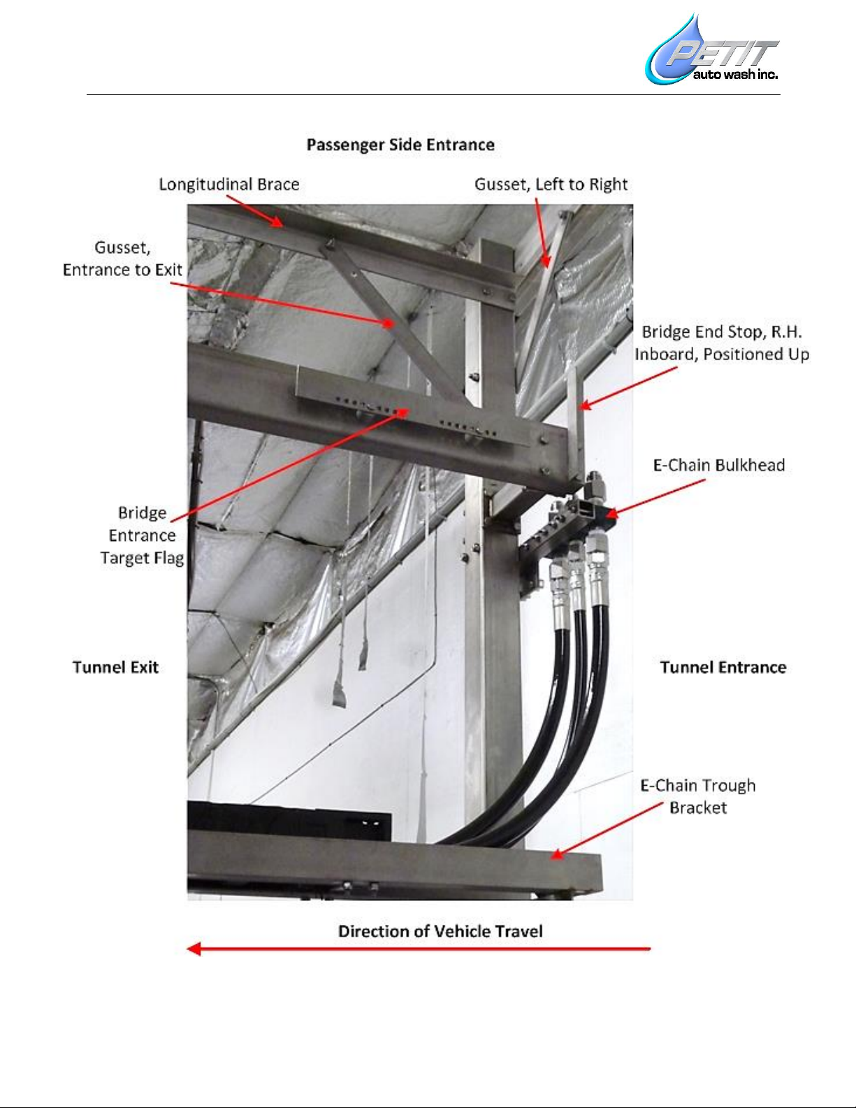
Stand up the remaining Exit or Entrance Cross Beam/ Leg assembly and attach the two Longitudinal
Braces and the Entrance to Exit Gussets, then fasten loosely to the floor.

Petit Auto Wash Inc.
360-t Installation Manual www.PetitAutoWash.com P a g e | 5
Accutrac 360-t Tunnel
Attach the D.S. & P.S. Main Rails snug, but do not fully tighten the fasteners. Be sure to identify the rails
correctly, placing them in the correct position with the 4-bolt flange holes towards the bottom.
Attach the E-Chain Trough with E-Chain in it, to the Passenger Side Legs.
At this point use a level and verify the legs are plumb from front-to-back and left-to-right. Push them
into position if needed, tighten all rail kit fasteners, recheck the legs and finally fully tighten the floor
anchors on all 6 legs. This step is important as it will insure that the upper framework stays plumb and
square. Do not over tighten the fasteners in the drive rails. This can crush the tubing and cause
alignment issues for the drive wheels.
The Entrance and Exit Proximity Target Flags are already mounted on the P.S. Main Drive Rail. Verify that
the flags are 4” from the end of the bridge rail. The Home Proximity Target Flag is already attached to
the D.S. Main rail. Verify that the flag is 26-1/4” from the entrance end of the D.S. Main Rail.
Bridge Rail End Stops are directional and are already fastened to the inboard side of the Main Rails, at
both the entrance and exit end. If the End Stops must be removed for any reason, verify that they are
installed before beginning the startup procedure.
Install the E-Chain Bulkhead on the P.S. Entrance Leg. (See drawing under section: 1.7 E-chain)

Petit Auto Wash Inc.
360-t Installation Manual www.PetitAutoWash.com P a g e | 6
Accutrac 360-t Tunnel
Accutrac 360-t Entrance

Petit Auto Wash Inc.
360-t Installation Manual www.PetitAutoWash.com P a g e | 7
Accutrac 360-t Tunnel
Accutrac 360-t Exit

Petit Auto Wash Inc.
360-t Installation Manual www.PetitAutoWash.com P a g e | 8
Accutrac 360-t Tunnel
Main Rail, P.S. Entrance
Main Rail, P.S. Exit

Petit Auto Wash Inc.
360-t Installation Manual www.PetitAutoWash.com P a g e | 9
Accutrac 360-t Tunnel

Petit Auto Wash Inc.
360-t Installation Manual www.PetitAutoWash.com P a g e | 10
Accutrac 360-t Tunnel

Petit Auto Wash Inc.
360-t Installation Manual www.PetitAutoWash.com P a g e | 11
Accutrac 360-t Tunnel
Raising the E-Chain

Petit Auto Wash Inc.
360-t Installation Manual www.PetitAutoWash.com P a g e | 12
Accutrac 360-t Tunnel
1.5. Raising the Bridge:
Note: Combined weight of Bridge & Cradle is 1,000 lbs. The steel Cradle is used to transport, lift and
position the Bridge into place. To assist in transport, casters are available for the cradle. Make sure
the Cradle is securely attached to the bridge and all the fasteners are tight.
Position the fork lift on the Exit side of the Bridge. If it is necessary to pick the Bridge up from the front
(entrance side), you must first unplug the power wires & remove both halves of the Front Cover.
Verify that the Bridge Proximity switches are adjusted back, nearly flush with the bridge plates, so they
will easily clear the rails & limit flags.
Remove the D.S. Main rail completely, or you can remove all but 1 bolt and swing the drive rail out of
the way without completely removing it. and lift the Bridge while clearing the E-Chain and P.S. Rail.
Then re-attach the D.S. Rail, side-shift and lower the Bridge into place.
If loading the bridge from the Exit end, leave 1 bolt in the Entrance end of the DS Main Rail, If loading
from the Entrance, leave one bolt in the opposite end.
Now remove the bolts that hold the Cradle to the Bridge and lower the Cradle to the ground.
Flip the Bridge Keeper Brackets 180-degrees and keep on the outboard side of the Bridge End Plates,
under the Rails. Verify that the Bridge End Stops are bolted on the inboard side of the Main Rails.
Unfold the Spray Arms. The spray arm breakaway force will be adjusted later.
Install the T-Bars and fold the excess length of photo-eye cables back up into the wire duct. Tuck the
sensor array junction box vent into the top of the T-bar. (Note that the PS T-bar Mount also holds a
photo-eye bracket. Use a level to make sure bracket is straight up/down. Note: The T-Bars are fastened
to their mounting blocks with a shear bolt. Do not over-tighten the shear bolt. Do not replace with a
regular bolt. Two replacement shear bolts are provided in the spare included parts kit.
Re-install and adjust the Entrance and Exit Prox Switches on the Bridge. The face of the prox switch
should be 3/16 to ¼” from its target flag. (The face of the prox switch will protrude approximately 3/4
to 13/16” beyond the plate it is mounted in).
Unfold the Top Washer, attach the 3/4” feed hose and install the cover.

Petit Auto Wash Inc.
360-t Installation Manual www.PetitAutoWash.com P a g e | 13
Accutrac 360-t Tunnel
Bridge, Inboard, P.S.

Petit Auto Wash Inc.
360-t Installation Manual www.PetitAutoWash.com P a g e | 14
Accutrac 360-t Tunnel
1.6. Breakaway:
Refer to Breakaway Tension Measurement and Breakaway, Parts Identification
Note that the Nozzle side of the Spray Arm is defined as the Front.
Attachment point for checking the breakaway tension is the recessed groove between the two center
nozzles approximately 45” above the ground.
Use the provided luggage scale to verify the spring heights below, which will result in the correct
breakaway force. Over tightening the spring will cause structural damage.
Prior to shipping the Upper Springs were properly adjusted but the Lower Spring tensions were backed
off and require setting prior to startup.
Upper Spring (Left/Right): = 29 lb. to the left.
Lower Spring (Front/Rear): = 42 lb. to the rear.
Important: The elastomeric springs will take an initial set. They must be re-tensioned again at 24 &
48hrs after the initial setup.

Petit Auto Wash Inc.
360-t Installation Manual www.PetitAutoWash.com P a g e | 15
Accutrac 360-t Tunnel

Petit Auto Wash Inc.
360-t Installation Manual www.PetitAutoWash.com P a g e | 16
Accutrac 360-t Tunnel

Petit Auto Wash Inc.
360-t Installation Manual www.PetitAutoWash.com P a g e | 17
Accutrac 360-t Tunnel
1.7. E-Chain:
At the Bridge, flip the Bridge E-Chain L-Bracket 180 degrees and re-fasten. Attach the free end of the E-
Chain to the L-Bracket.
Refer to Bulkhead Hoses Attach the (2) 3/4” & (1) 1/2” high pressure hoses. Feed the 1/4” quad tubing
alongside the 5/8” stainless steel tubing up into the center of the Bridge and insert the 4 tubes into the
y-connectors. Be sure to match like-colors. Tie-wrap the quad tube neatly to the cable-tie holders
located on the trolley e-chain trough.
Route the two multi-conductor cables exiting the E-Chain above the 3/4”, top washer hose and into the
Bridge Junction Box. While facing the junction box the Control Cable (Grey) goes into the left cord grip
(P.S.) and the Motor cable (Dark Blue) goes into the right cord grip (D.S.). Be sure to fasten the
grounding clips over the cable shielding. Refer to the electrical schematics for wire termination.
Important: When terminating individual wires in terminal blocks, strip the insulation 3/8” -7/16” to
ensure a proper connection.
At opposite end of E-Chain, connect the hoses to the bulkhead. Route the two multi-conductor cables
and quad air tubing to the cable tie mounting plate. (See Drawing Below)
Important: Note that the Electric Cables and Quad Tubing (air lines) come from the factory cable tied to
the moving end (machine end) of the energy chain. You will need to tie wrap them at the fixed end of
the E-chain. Prior to tie wrapping the electric cables and quad tubing you must ensure they are placed
in the middle of the bend radius of the e-chain, at the 180-degree bend in the chain. To do this grab and
pull each cable or tube and pull as far as possible out of the e-chain, then push them into the e-chain as
far as possible. Pull back out half the distance and then tie wrap to the last e-chain crossbar.
Note that the ¾” & ½” high pressure hoses are designed to be free floating. Do not tie down either end
of the high-pressure hoses.
Important: At the e-chain bulkhead, adjust the attachment point of the cables and hoses so that they
do not sag and will not rub anything.
Run hoses and cables from the E-Chain Bulkhead back to their termination points in the mechanical
room.

Petit Auto Wash Inc.
360-t Installation Manual www.PetitAutoWash.com P a g e | 18
Accutrac 360-t Tunnel
E-Chain Bulkhead & Crossover Plumbing Group (Optional)

Petit Auto Wash Inc.
360-t Installation Manual www.PetitAutoWash.com P a g e | 19
Accutrac 360-t Tunnel
1.8. Bridge Mount LED (144w):
The Bridge Mount LED is optional and attaches to the exit side of the Bridge.
Note: For machines produced before 1/15/2015, refer to additional LED Retrofit instructions before
proceeding with this installation.
Unpack the LED Light bar. Measure and find the centerline of the light bar. Position brackets so they are
26 1/2” from center and tighten the set screws, then tighten the thumb wheels that control the angle.
The LED Light bar has quick disconnect leads on both sides. Find the cord that has a waterproof plug
inserted into the quick disconnect. This end of the LED Light must be oriented to the driver side. Bundle
and tie wrap the cord to the D.S. light bracket as shown below.
Using the included 1/4-20 x 1” bolts, fender washers and locking nuts, place the LED light on top of the
Bridge L brackets, and tighten the fasteners. Fender washers should go on the LED light side.
Land the wiring in the Bridge Junction Box using the existing multi-conductors as shown in the LED
schematics.
At the 360 Control Panel, if necessary, install the LED Relay bank onto the Motor terminal strip din rail at
the bottom of the panel. Wire the LED 24VDC power supply, light controller, and relay bank per the LED
schematics.
Bridge Mount LED

Petit Auto Wash Inc.
360-t Installation Manual www.PetitAutoWash.com P a g e | 20
Accutrac 360-t Tunnel
2. Mechanical Room Equipment
2.1. 360-t HMI Control Panel:
Important Wiring Instructions for all equipment
1. If the electrical service is a Delta (also known as a High-Leg) system, refer to schematics before wiring
the Accutrac 360 Control Panel.
2. Refer to the installation manual, equipment/electrical schedule and the schematics.
3. Wire the equipment according to NEC as well as state and local codes.
4. Insure proper grounding of control panel as well as proper grounding/bonding of the incoming
electrical service.
5. Always run low-voltage control wires in separate conduits away from power wires.
6. Never drill holes or run wiring into top of electrical enclosures. Use bottom entry or lowest possible
entry point on side of enclosure. Top entry will void the warranty
7. For Accutrac 360s, run the two 25-conductor umbilical cables from the control panel to bay equipment
in separate 1-1/4” conduits. Whenever possible, especially on long parallel runs, keep the lines at
least 12” away from each other. Follow instructions in the Appendix for stripping insulation from the
25-conductor cables.
Locate the Control Panel as close to the bay equipment as possible. Mount the panel to the wall at a
height that the Touch-Screen is readily accessible. Route the two multi-conductor cables from the bay
equipment to the panel through separate 1-1/4” diameter or larger conduits. On long runs it is
recommended that the electrician install two separates 12” square junction boxes near the wash bay
and route the 25- conductor cables through the boxes. In the future when the moving part of the
control cable needs replaced it can be spiced at the junction box rather than replacing the entire run.
Refer to the Schematics for the Power & Control wiring requirements. Please note that the Computer
Control also requires a Cat-5 Ethernet connection to the customer’s LAN (Local Area Network).
Locate and land the following external inputs into the Input Isolation relays. Factory supplied Input relay
coils are 24VAC/DC. 120VAC coils are available upon request.
-Input #1022: Conveyor Pulse Signal (verify signal is received at consistent intervals)
-Input #1023: Conveyor Entrance/Gate Photo Eye Signal (“On” when blocked by vehicle)
-Input #1024: Conveyor Running Signal (“On” whenever conveyor is running)
Note: Inputs #1022 & #1023 either need to be wired directly from each device or from a buffer relay
fired directly by the devices. Do not use tunnel controller “Mirror” outputs as this will result in
unreliable input timing and would cause the 360-t to malfunction.
Table of contents
Popular Paint Sprayer manuals by other brands

Carlisle
Carlisle DeVilbiss JGA-510 Service manual

Graco
Graco HydroShield WMBH00 Instructions - parts

Task Force Tips
Task Force Tips MASTER INSTRUCTIONS FOR SAFE OPERATION AND MAINTENANCE

Enduraplas
Enduraplas STEEL BOOM owner's manual

Solo
Solo 425 Classic Service manual

ANI
ANI A/206 Operation and maintenance manual