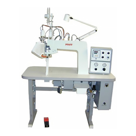
Pfaff 3568-12/22 User manual

3568-12/22
Instruction manual
296-12-17973
Betriebsanleitungengl.03.97

At the time of printing, all information and illustrations contained in this document were up to
date.
Subject to alteration!
The reprinting, copying or translation of PFAFF Instruction Manuals, whether in whole or in
part, is only permitted with our previous authorization and with written reference to the
source.
G.M. PFAFF
Aktiengesellschaft
Postfach 3020
D-67653 Kaiserslautern
Königstr. 154
D-67655 Kaiserslautern
Editing / Illustrations
HAAS-Publikationen GmbH
D-53840 Troisdorf

Indice
Contents ...............................................................................Chapter - Page
1Safety ..................................................................................................... 1- 1
1.01 Directives...................................................................................................................1- 1
1.02 General notes on safety ............................................................................................. 1-1
1.03 Safety symbols .......................................................................................................... 1 - 2
1.04 Important points for the user ..................................................................................... 1 - 3
1.05 Operating and specialist personnel ............................................................................ 1 - 3
1.05.01 Operating personnel................................................................................................... 1 - 3
1.05.02 Specialist personnel ................................................................................................... 1 - 4
1.06 Danger .......................................................................................................................1- 5
2Proper use .............................................................................................. 2- 1
3Specifications .......................................................................................... 3- 1
4Disposal of the machine ............................................................................ 4- 1
5Testing according to EN 60204-3-1.............................................................. 5- 1
6Transport packaging and storage ............................................................... 6- 1
6.01 Transport to the customer’s premises ....................................................................... 6 - 1
6.02 Transport within the customer’s premises ................................................................ 6 - 1
6.03 Disposal of the packaging .......................................................................................... 6 - 1
6.04 Storage ......................................................................................................................6- 1
7Explanation of the symbols ....................................................................... 7- 1
8Controls .................................................................................................. 8- 1
8.01 On/off switch ............................................................................................................. 8 - 1
8.02 EMERGENCY OFF switch.......................................................................................... 8 - 1
8.03 Jig changeover control ............................................................................................... 8 - 2
8.04 Table control .............................................................................................................. 8 -2
8.05 Foot switch ................................................................................................................ 8 -3
8.06 Start controls.............................................................................................................. 8- 4
8.07 Control panel on the sewing station........................................................................... 8 - 5
8.07.01 Display ....................................................................................................................... 8 - 5
8.07.02 Operation mode keys................................................................................................. 8 - 6
8.07.03 Program station keys ................................................................................................. 8 - 6
8.07.04 Red function keys ...................................................................................................... 8 - 7
8.07.05 Green function keys ................................................................................................... 8 - 8
8.08 Control panel on the folder station ............................................................................. 8 - 9
8.08.01 Operation mode keys................................................................................................. 8 - 9
8.08.02 Station keys ............................................................................................................... 8 - 9
8.08.03 Function keys.............................................................................................................8-10

Indice
Contents ...............................................................................Chapter - Page
9Mounting and commissioning the machine ................................................. 9- 1
9.01 Mounting.................................................................................................................... 9- 1
9.02 Commissioning the machine...................................................................................... 9 - 2
9.02.01 Turning the machine on/off ........................................................................................ 9 - 3
9.02.02 Adjusting zero point ................................................................................................... 9 - 4
10 Preparation ........................................................................................... 10 - 1
10.01 Inserting the needle ................................................................................................. 10 - 1
10.02 Winding the bobbin thread, adjusting the thread tension ......................................... 10 - 2
10.03 Changing the bobbin ................................................................................................ 10 - 3
10.03.01 Bobbin change, bobbin case and bobbin thread tension .......................................... 10 - 3
10.03.02 Changing the bobbin from the top in MANUAL mode.............................................. 10 - 4
10.03.03 Changing the bobbin from the top in AUTOMATIC mode ........................................ 10 - 5
10.04 Threading the needle thread .................................................................................... 10 - 6
10.05 Program number selection....................................................................................... 10 - 7
10.06 Automatic change in program station ...................................................................... 10 - 8
10.07 Jig monitor (optional)................................................................................................ 10 - 9
10.07.01 Activating jig monitor (menu) ................................................................................... 10 - 9
10.07.02 Determining the jig code .......................................................................................... 10 - 10
10.08 Placement of the cuttings ........................................................................................ 10 -11
11 Programing and sewing .......................................................................... 11 - 1
11.01 Brief description of Input mode................................................................................ 11 - 1
11.01.01 Direct functions........................................................................................................ 11- 1
11.01.02 Summary of the functions in the 1st menu level ..................................................... 11 - 1
11.01.03 Summary of the functions in the 2nd menu level..................................................... 11 - 2
11.02 Description of the menu levels ................................................................................ 11 - 3
11.02.01 1st menu level ......................................................................................................... 11 -3
11.02.02 Entering the 2nd menu level .................................................................................... 11 - 3
11.02.03 2nd menu level......................................................................................................... 11 -3
11.03 Examples for selecting functions ............................................................................. 11 - 4
11.03.01 Selecting a direct function........................................................................................ 11 - 4
11.03.02 Selecting a function from the 1st menu level........................................................... 11 - 4
11.03.03 Selecting a subfunction from the 2nd menu level .................................................... 11 - 5
11.04 Explanation of the menu functions........................................................................... 11 - 6
11.04.01 Functions in the 1st menu level ............................................................................... 11 - 6
11.04.02 Functions in the 2nd menu level .............................................................................. 11 - 8
11.05 Sewing ..................................................................................................................... 11-13
11.05.01 Sewing in the AUTOMATIC mode ........................................................................... 11 -13
11.05.02 Sewing in the MANUAL mode ................................................................................. 11 - 14
11.05.03 Disturbances ............................................................................................................ 11-15
12 Care and maintenance ............................................................................ 12 - 1
12.01 Cleaning the machine............................................................................................... 12 - 2
12.02 Lubricating the sewing head .................................................................................... 12 - 3

Indice
Contents ...............................................................................Chapter - Page
12.03 Lubricating the zigzag drive ...................................................................................... 12 - 4
12.04 Lubricating the carriage guides of the X/Y control .................................................... 12 - 5
12.05 Lubricating jig changeover........................................................................................ 12 - 6
12.06 Cleaning the blower air filter .................................................................................... 12 - 7
12.07 Compressed air unit ................................................................................................. 12 - 8
12.07.01 Checking and regulating air compression................................................................. 12 - 8
12.07.02 Cleaning the air filter ................................................................................................ 12 -8
12.07.03 Checking and topping up the oil level....................................................................... 12 - 9
12.07.04 Emptying the water trap .......................................................................................... 12 - 10
12.07.05 Adjusting the drip feed rate on the oil vaporizer ....................................................... 12 -10
12.07.06 Cleaning the vaporizer jet ......................................................................................... 12 - 10
13 Adjustment ........................................................................................... 13 - 1
13.01 Notes on adjustments.............................................................................................. 13 - 1
13.02 Tools, gauges and other accessories ....................................................................... 13 - 1
13.03 Abbreviations ........................................................................................................... 13 - 1
13.04 Removing/inserting sewing machine head............................................................... 13 - 2
13.05 Checking and adjustment aids ................................................................................. 13 - 3
13.06 Adjusting the sewing machine head ........................................................................ 13 - 4
13.06.01 Counterweight ......................................................................................................... 13 - 4
13.06.02 Centering the needle in the needle hole (in the direction of sewing)........................ 13 - 5
13.06.03 Needle bar-parallel guide .......................................................................................... 13 - 6
13.06.04 Setting zero stitch .................................................................................................... 13 -7
13.06.05 Zigzag stitch movement........................................................................................... 13 - 8
13.06.06 Needle penetration symmetry ................................................................................. 13 - 9
13.06.07 Centering the needle in the needle hole (across the direction of sewing) ................ 13 - 10
13.06.08 Zigzag stitch width ................................................................................................... 13 - 11
13.06.09 Hook bearing............................................................................................................ 13-12
13.06.10 Hook lubrication ....................................................................................................... 13 -13
13.06.11 Gear box drive belt................................................................................................... 13 - 14
13.06.12 Preadjusting the needle height................................................................................. 13 -15
13.06.13 Needle bar rise, hook-to-needle clearance and bobbin case..................................... 13 -16
13.06.14 Final adjustment of needle height ............................................................................ 13 -17
13.06.15 Bobbin case opener position .................................................................................... 13 - 18
13.06.16 Bobbin case opener movement ............................................................................... 13 -19
13.06.17 Counter presser lifting stroke................................................................................... 13 -20
13.06.18 Needle guard movement ......................................................................................... 13 - 21
13.06.19 Needle guard position .............................................................................................. 13 -22
13.06.20 Counter presser height ............................................................................................ 13 - 23
13.06.21 Counter presser position.......................................................................................... 13 -24
13.06.22 Presser..................................................................................................................... 13 - 25
13.06.23 Needle thread tension release ................................................................................. 13 - 26
13.06.24 Thread check spring ................................................................................................. 13 -28
13.06.25 Thread puller ............................................................................................................ 13 -29
13.06.26 Bobbin winder .......................................................................................................... 13 -30
Indice
Contents ...............................................................................Chapter - Page
13.06.27 Synchronizer ............................................................................................................ 13-31
13.07 Adjusting the thread trimmer ................................................................................... 13 -32
13.07.01 Mounting/dismounting the control unit .................................................................... 13 - 32
13.07.02 Preadjusting the control cam ................................................................................... 13 -33
13.07.03 Roller lever ............................................................................................................... 13 - 34
13.07.04 Latch ........................................................................................................................ 13 -35
13.07.05 Engaging solenoid .................................................................................................... 13 - 36
13.07.06 Actuating lever ......................................................................................................... 13-37
13.07.07 Engaging lever ......................................................................................................... 13 -38
13.07.08 Cutting test ..............................................................................................................13-39
13.07.09 Thread catcher position............................................................................................ 13 - 40
13.07.10 Control cam (final adjustment) and catch spring ...................................................... 13 -41
13.08 Adjusting the folding and feed devices .................................................................... 13 -42
13.08.01 Adjusting the switch vanes on the X/Y control ......................................................... 13 - 42
13.08.02 Home position of the transport arm ......................................................................... 13 - 43
13.08.03 Feed changeover ..................................................................................................... 13 -44
13.08.04 Sewing jig position at the sewing station................................................................. 13 - 45
13.08.05 Aligning the sewing jig ............................................................................................. 13 -46
13.08.06 Sewing jig position at the folding station (home position) ........................................ 13 - 47
13.08.07 Proximity switch ...................................................................................................... 13 - 48
13.08.08 Height of the loading plate ....................................................................................... 13 - 49
13.08.09 Height of pocket plate support................................................................................. 13 -50
13.08.10 Basic dimensions of the folder................................................................................. 13 -51
13.08.11 Height of the folder device....................................................................................... 13 -52
13.08.12 Position of pocket plate arm .................................................................................... 13 -53
13.08.13 Pocket plate position................................................................................................ 13 -54
13.08.14 Pocket plate height .................................................................................................. 13 - 55
13.08.15 Die ........................................................................................................................... 13 - 56
13.08.16 Position of folder plates ........................................................................................... 13 -58
13.08.17 Actuating sequence of the folder plates................................................................... 13 -59
13.08.18 Position of corner folder........................................................................................... 13 -61
13.08.19 Roller lever valves .................................................................................................... 13 -62
13.08.20 Parallelism of seam to pocket .................................................................................. 13 -63
13.08.21 Centering the pocket seam...................................................................................... 13 - 64
13.08.22 Distance of seam to pocket ..................................................................................... 13 -65
13.08.23 Seam backtack distance .......................................................................................... 13 -66
13.09 Shaping folder plates................................................................................................ 13 - 67
13.09.01 New installation / self-manufacture of folder plates ................................................. 13 -67
13.09.02 Slanting the lateral folder plates ............................................................................... 13 -68

1 - 1
Safety
1 Safety
1.01 Directives
This machine was built in accordance with the following European regulations:
●EC Machine Directive (89/392/EEC, 91/368/EEC, 93/44/EEC, 93/68/EEC)
●Safety of Appliances Law, Machine Ordinance - 9GSGV
●EC Directive „Electromagnetic Compatibility“ (89/336/EEC, 92/31/EEC, 93/68/EEC)
●EN 60204-1 Safety of Machines, Electrical Equipping of Industrial Machines: Part 3
●EN 292 Parts 1 and 2: 1991 Safety of Machines (Basic Terms)
●EN 294 Safety of Machines; safety clearance margins for avoiding dangerous situations
for the upper limbs
●EN 349 Safety of Machines; minimum safety clearances for avoiding the crushing of
body parts
●EN 418 Safety of Machines; devices for turning off the machine in emergencies
●DIN 45635 Measurement of noise levels
In addition to this Instruction Manual, also observe all generally accepted, statutory and
other regulations and legal requirements - also those of the country in which the machine
will be operated - and all valid environmental protection regulations!
Applicable local regulations of the social insurance society for occupational accidents or
other supervisory organizations are to be strictly adhered to!
1.02 General notes on safety
●This machine must only be operated by adequately trained operators and only after
having completely read and understood the Instruction Manual!
●All Notes on Safety and Instruction Manuals of the motor manufacturer are to be read
before operating the machine!
●The Danger and Safety Instructions on the machine itself are to be followed!
●This machine must only be used for the purpose for which it is intended and must not be
operated without its safety devices. All applicable safety regulations must be observed.
●When sewing parts (e.g. needle, presser foot, needle plate, feed dog or bobbin) are
exchanged, when the machine is being threaded, when the machine is left unattended
and during maintenance work, the machine is to be separated from the power supply by
turning off the On/Off switch or removing the plug from the mains!
●Daily maintenance work must only be carried out by appropriately trained personnel!

1 - 2
Safety
●Repair work and special maintenance work must only be carried out by specialists or
appropriately trained personnel!
●For maintenance and repair work on pneumatic devices, the machine must be separated
from the source of pneumatic power! The only exceptions allowed are for adjustments
and function testing by appropriately trained personnel!
●Work on electrical equipment must only be carried out by appropriately trained specialist
personnel!
●Work is not permitted on parts and equipment which are connected to the power supply!
Exceptions to this are contained in the regulations EN 50110.
●Modifications and alterations to the machine must only be carried out pursuant to all
relevant safety regulations!
●Only spare parts which have been approved by us are to be used for repairs!
We expressly point out that any replacement parts or accessories not supplied by us
have not been tested and approved by us. The installation and/or use of any such
products may result in negative changes to the constructional characteristics of the
machine. We are not liable for any damage which may be caused by non-original parts.
1.03 Safety symbols
Danger!
Points to be observed.
Danger of injury to operating and specialist personnel!

1 - 3
Safety
1.04 Important points for the user
●This Instruction Manual is a component part of the machine and must be available to the
operating personnel at all times.
The Instruction Manual must be read before operating the machine for the first time.
●The operating and specialist personnel is to be instructed on the safety equipment of the
machine and regarding safe work methods.
●It is the duty of the user to only operate the machine in perfect running order.
●It is the obligation of the user to ensure that none of the safety mechanisms are removed
or deactivated.
●It is the obligation of the user to ensure that only authorized persons operate and work on
the machine.
Further information can be obtained at the point of sale.
1.05 Operating and specialist personnel
1.05.01 Operating personnel
Operating personnel are persons responsible for the preparation, operating and cleaning of
the machine as well as taking care of problems arising in the sewing area.
The operating personnel is obliged to observe the following points and must:
●always observe the Notes on safety in the Instruction Manual!
●never use any working methods which could reduce the level of safety in using the
machine!
●not wear loosely fitting clothing or jewelery such as chains or rings!
●also ensure that only authorized persons have access to the potentially dangerous area
around the machine!
●always immediately report to the user any changes in the machine which may reduce its
level of safety!

1 - 4
Safety
1.05.02 Specialist personnel
Specialist personnel are persons who have completed expert education/training in the fields
of electrics, electronics, pneumatics and mechanics. They are responsible for the lubrication,
maintenance, repair and adjustment of the machine.
The specialist personnel is obliged to observe the following points and must:
●always observe the Notes on Safety in the Instruction Manual!
●switch off the On/Off switch before carrying out adjustments or repairs and ensure that it
cannot be switched on again unintentionally!
●never work on parts and devices which are still connected to the power supply! The only
exceptions to this directive are found in the regulations EN 50110.
●for maintenance and repair work on pneumatic devices, the machine must be separated
from the source of pneumatic power! The only exceptions allowed are for function
testing.
●replace the protective coverings and close the electrical control box after all repairs or
maintenance work!

1 - 5
Safety
1.06 Danger
A working area of 1 meter is to be kept free both in front of and behind the
machine while it is in operation, so that it is always easily accessible.
Never reach into the sewing area while sewing!
Danger of injury by the needle!
Never leave objects on the table or in the needle plate area while adjusting the
machine settings! Objects can become trapped or be slung away!
Danger of injury!
Fig. 1 - 01
Überw.
Bügel
AUS
EIN
S 98.1
32
1
Before operating the machine, make sure that safety switch 1in the control box
is switched on. Do not operate the machine under any circumstances if the
safety switch 1has been turned off! Danger of injury!
The machine must not be operated without safety bar2!
Danger of injury by the transport arm when it is swinging back and forth!
The machine must only be operated with the cover 3closed!
Danger of injury by the moving parts of the XY control!
The machine must not be operated without the sewing head’s protective
devices such as the take-up lever guard and the belt guard!
Danger of injury by the movement of the take-up lever or by the rotating V-belt!

Proper use
2 Proper use
Fig. 2 - 01
ThePFAFF 3568-12/22 isused forfolding andsewing on pocketson jeans,workwear, shirts
and similar garments. Seams are created using the program functions.
Any and all uses of this machine which have not been approved of by the
manufacturer are considered to be inappropriate! The manufacturer cannot be
held liable for any damage caused by the inappropriate use of the machine!
The appropriate use of the machine means that all operational, adjustment,
maintenance and repair measures required by the manufacturer are to be
observed!
2 - 1

3 - 1
Specifications
3 Specifications
Sewing head: ........................................................................... PFAFF 918 -650/00 -900/51
Sewing speed: .......................................................................................... max. 4100 spm-1
Stitch length:..................................................................................................... max. 6 mm
Stitch type:.................................................................................................. 301 (lockstitch)
304 (zigzag lockstitch)
Needle system:..............................................................................................1955-07-MR5
Needle size: ................................................................................................... 110 - 140 Nm
Sewing motor: ................................................... AEG Permanent Magnet AC Servo-Motor
Motor speed: .............................................................................................max. 4500 rpm-1
Connection voltage: ............................................................................230 V, 50 - 60 Hz AC
Power requirement: .................................................................................. approx. 1000 VA
Working air pressure: ...........................................................................................min. 6 bar
Air consumption:.................................................................................... approx. 27 l / cycle
Working noise level:
Emission at workplace at n = 4100 spm-1: .............................................................78 dB(A)
Dimensions of machine:
Length:................................................................................................... approx. 2200 mm
Width: ..................................................................................................... approx. 1500 mm
Height: .................................................................................................... approx. 1400 mm
Net weight: .................................................................................................. approx. 653 kg
Gross weight:............................................................................................... approx. 840 kg

Disposal of the machine
4 Disposal of the machine
●The proper disposal of the machine is the responsibility of the customer.
●The materials used are steel, aluminium, brass and various plastics. The electrical
equipment consists of plastics and copper.
●The machine must be disposed of in accordance with applicable local environmental
protection regulations.
Special care is to be taken that parts soiled by lubricants are separately
disposed of in accordance with the applicable local environmental protection
regulations!
4 - 1

5 - 1
Testing according to EN 60204-3-1
5 Testing according to EN 60204-3-1
Prior to delivery, the machine was tested according to EN 60204-3-1 version 1/86.
The following tests were carried out on the machine:
●proper connection of the protective conductor systems
a ) visual check
b ) testing connection of protective conductor to ensure that it is not defective
●insulation test
●voltage test
●performance test

Transport packaging and storage
6 Transport packaging and storage
6.01 Transport to the customer’s premises
Within Germany, machines are delivered without packaging.
Machines for export are packaged.
6.02 Transport within the customer’s premises
The manufacturer bears no liability for transport within the customer’s premises or to the
location of use.
6.03 Disposal of the packaging
The packaging of these machines consists of paper, cardboard and VCE fibre. The proper
disposal of the packaging is the responsibility of the customer.
6.04 Storage
The machine can be stored for up to 6 months if not in use. During this time it should be
protected from dust and moisture.
For longer storage the individual parts of the machine, especially the moving parts, should
be protected against corrosion, e.g. by a film of oil.
6 - 1

Explanation of the symbols
7 Explanation of the symbols
In this Instruction Manual, tasks to be carried out and important information are drawn to
your attention by symbols.
The symbols have the following meanings:
Note, information
Cleaning, care
Lubrication
Servicing, repairing,
adjustment, maintenance
7 - 1

Controls
8 Controls
8.01 On/off switch
●By turning switch 1, the power supply to
the machine is switched on or off.
Fig. 8 - 01
8 - 1
8.02 EMERGENCY OFF switch
●By pressing the EMERGENCY OFF
switch 1, the machine can be stopped in
case of an emergency.
●Before the machine is turned back on,
the EMERGENCY OFF switch 1must be
released by pulling it up.
Fig. 8 - 02
1
1

Controls
8.03 Jig changeover control
●When control 1is activated, the sewing
jig and the transport arm (jig changeover)
are disconnected.
8.04 Table control
●When control 1is activated, the retaining
flap for the cuttings is raised so that the
workpiece can be positioned.
Fig. 8 - 03
8 - 2
Fig. 8 - 04
1
1

Controls
8 - 3
8.05 Foot switch
●The function of the foot switch 1can be
adjusted to the various requirements for
placing in the workpiece.
●The foot switch is adjusted via the menu.
Fig. 8 - 05
1
By switching the functions HOME POSITION POCKET PLATE IN FRONT and PLAIN FABRIC
on or off, the following menu combinations can be created:
Menu combinations Foot switch functions
HOME POSITION POCKET PLATE IN FRONT on
PLAIN FABRIC on
HOME POSITION POCKET PLATE IN FRONT on
PLAIN FABRIC off
HOME POSITION POCKET PLATE IN FRONT off
PLAIN FABRIC off
HOME POSITION POCKET PLATE IN FRONT off
PLAIN FABRIC on Move forward pocket plate.
1.Operation of switch:
Move forward pocket plate.
2.Operation of switch:
Lower pocket plate.
(When the foot switch is activated
again, the pocket plate remains raised
so that the material can be aligned.)
Lower pocket plate.
(When the foot switch is activated
again, the pocket plate remains raised
so that the material can be aligned.)
Refer to chapter 11 Programming and sewing for information on selecting
functions.
no function
Table of contents
Other Pfaff Sewing Machine manuals

Pfaff
Pfaff expression 2026 User manual

Pfaff
Pfaff SZA-645F User manual

Pfaff
Pfaff perfomance 2054 User manual

Pfaff
Pfaff hobbylock 2.0 User manual

Pfaff
Pfaff Automatic 260 User manual

Pfaff
Pfaff 918 User manual

Pfaff
Pfaff coverlock 4872 User manual

Pfaff
Pfaff 1245 User manual

Pfaff
Pfaff 212 User manual

Pfaff
Pfaff 230 Automatic User manual

Pfaff
Pfaff POWERline 2591 ME User manual

Pfaff
Pfaff 3586-25 Series User manual

Pfaff
Pfaff Tiptronic 6230 User manual

Pfaff
Pfaff 900/51 User manual

Pfaff
Pfaff creative 7560 User manual

Pfaff
Pfaff 463 User manual

Pfaff
Pfaff 918 Guide

Pfaff
Pfaff 918 User manual

Pfaff
Pfaff perfomance 2058 User manual

Pfaff
Pfaff HD SCREEN User manual