Pfaff hobby GrandQuilter 1200 User manual

hobby GrandQuilter
1200
104 22 54-96
Ver: 27 Aug 2009
© 2009 VSM Group AB - All Rights Reserved.

2 104 72 63-26
Contents
Foreword .......................................................................................................................................3
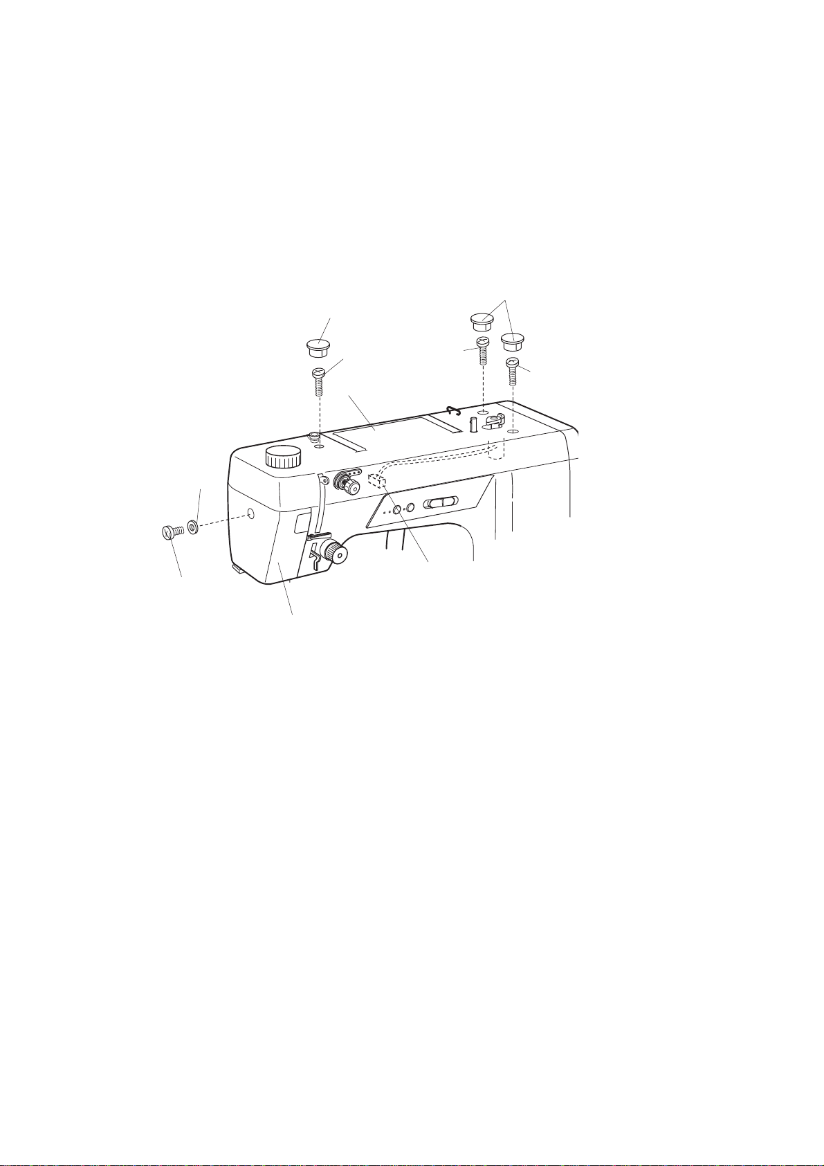
Replacing the External Parts.........................................................................................................4
Face Plate .....................................................................................................................................4
Top Cover......................................................................................................................................4
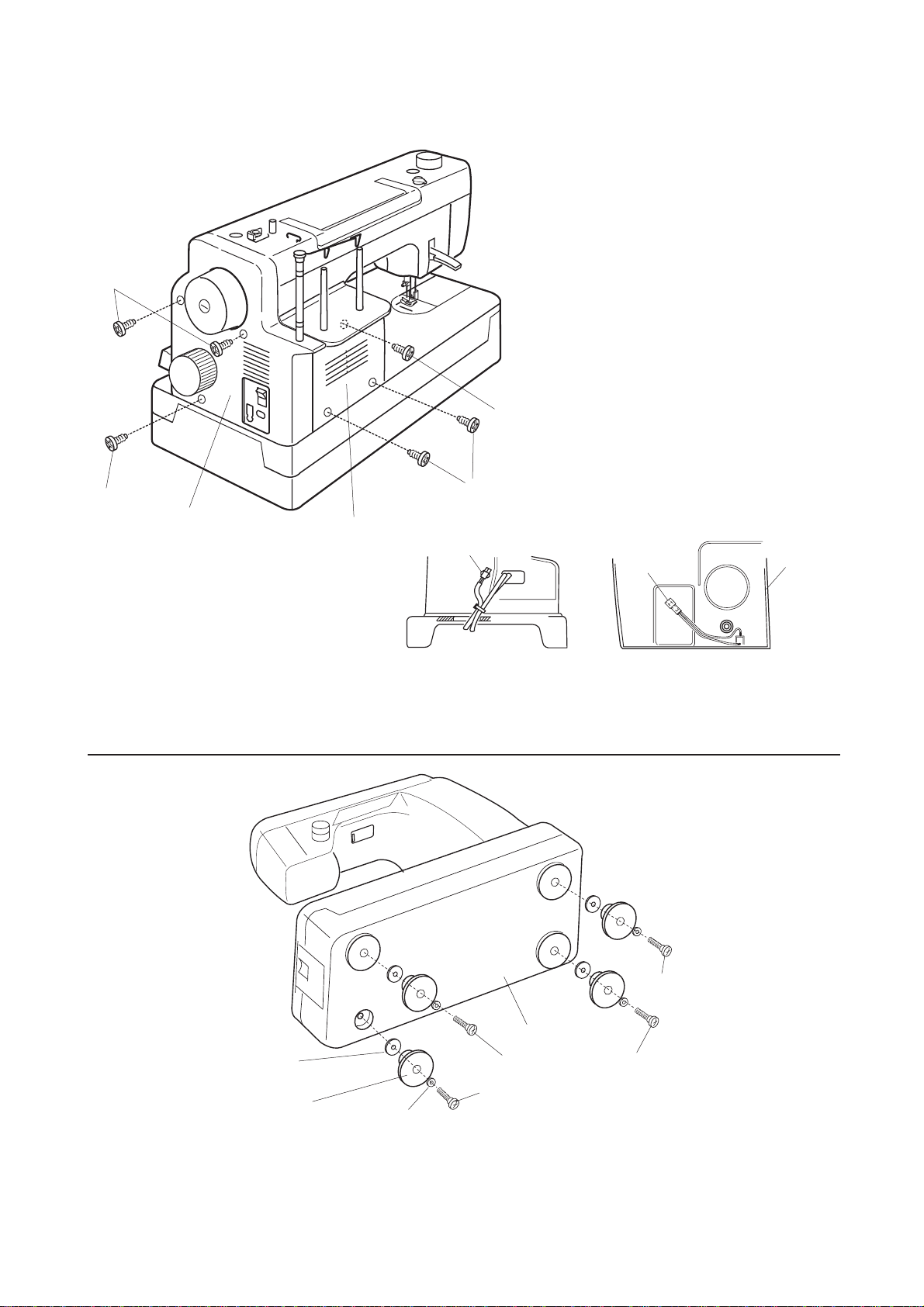
Belt Cover......................................................................................................................................5
Motor Cover...................................................................................................................................5
Base ..............................................................................................................................................5
Adjustment of the needle bar height..............................................................................................6
Adjustment of the timing of the hook in relation to the needle.......................................................8
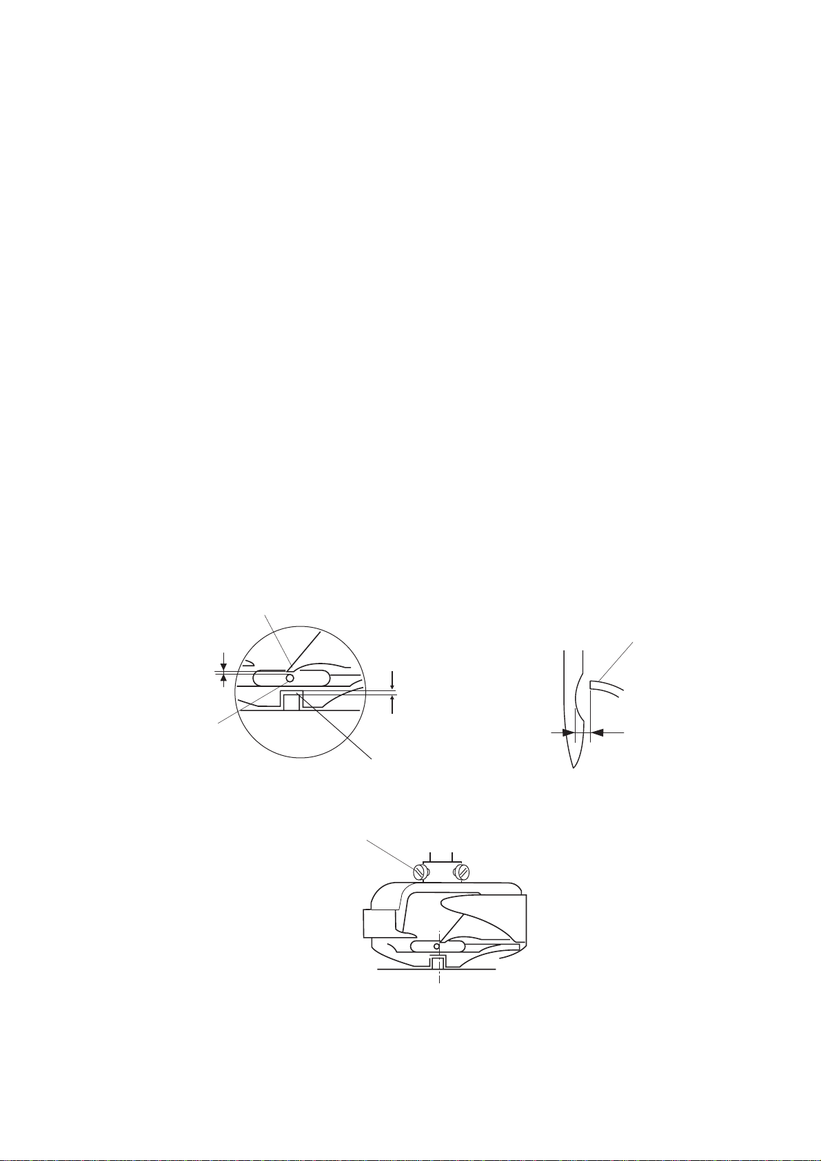
Adjustment of the clearance between needle and point of hook...................................................9
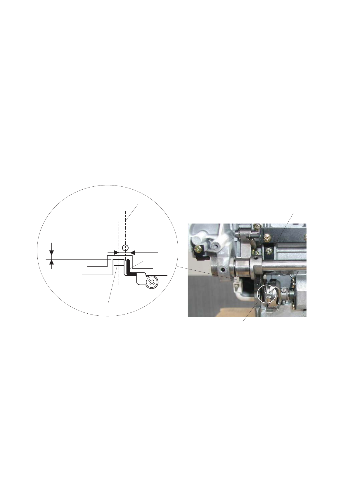
Adjustment of bobbin case position finger...................................................................................10
Adjustment of the presser bar height and alignment...................................................................11
Adjustment of the knee lifter lever...............................................................................................12
Adjustment of the Feed Cam Timing...........................................................................................13
Adjustment of the Feed Lifting Cam Timing................................................................................14
Adjustment of the parallelism and lengthwise movement of the Feed Dog ................................16
Adjustment of synchronizer.........................................................................................................17
Adjustment of bobbin thread tension...........................................................................................18
Adjustment of pre-tension dial.....................................................................................................18
Adjustment of thread check spring stroke ...................................................................................19
Replace and Adjust the Thread Guide Plate ...............................................................................20
Adjustment of the Fixed Cutter Knife...........................................................................................21
Adjustment of the needle to cutter cam timing............................................................................24
Adjustment of the thread drawing lever.......................................................................................25
Adjustment of the auto tension release.......................................................................................26
Thread Cutter Troubleshooting....................................................................................................27
Adjustment of bobbin winder stopper..........................................................................................28
Replacing the Electronic Components ........................................................................................29
Location of the Electronic Components.......................................................................................29
Location of the Connectors..........................................................................................................29
Internal Wiring .............................................................................................................................30
Replace the Circuit Board-A........................................................................................................31
Replace the Circuit Board-F and Slide Volume...........................................................................32
Replace the Light Bulb ................................................................................................................32
Replace the motor and Adjust the motor belt tension..................................................................34
Replace the transformer..............................................................................................................35
Replace the Machine Socket.......................................................................................................35

104 72 63-26 3
Foreword
The purpose of this service manual is to assist you in quick and correct repairing of the machines.
Adjustments should only be made if the settings deviate from the requirements described herein.
When checking or adjusting a machine, always proceed in the order of the work steps prescribed.
For easier reference every work step is marked with a dot.
When assembling dismantled machines, adjust the machine to approximately the right settings.
This facilitates the subsequent fine adjustments.
Unless otherwise specified, the hand wheel must always be turned forward.
When carrying out maintenance work on live parts or in their proximity, the machine is to be separated
from the power supply by unplugging the lead cord from the electrical socket.
For the proper adjustment of the machine, the following gauges and tools are required:
1,5 mm Allen key 07-433 005-28/000
2 mm Allen key 07-433 005-30/000
2.5 mm Allen key 07-433 005-40/000
Phillips Size 0 - small 07-434 001-15/000
Phillips Size 1 - medium 07-434 001-18/000
Phillips Size 2 - big 07-434 001-20/000
Subject to alterations in design and dimensions.

(A)
(B)
(E)
(H)
(C)
(C)
(G)
(D) (D)
(D)
4 104 72 63-26
Replacing the External Parts
Face Plate
Remove the setscrew (4 x 10) (A) and washer (B).
Remove the face plate (G).
Top Cover
Remove the caps (C) and setscrews (4 x 25) (D).
Lift the top cover (E) and pull out the motor connector (H).

(A)
(B)
(D)
(C)
(A)
(C)
(F) (D)
(E)
(A)
(A)
(A)
(A)
(B)
(C)
(D)
(E)
104 72 63-26 5
Belt Cover
• Remove the 3 setscrews (4 x 12) (C) and remove the belt cover (D).
Pull out the socket connector from the printed circuit board UD connector .
NOTE: When attaching the belt cover, engage the hooks with the motor cover.
Motor Cover
• Remove the Belt cover (D) first
• Remove the 3 setscrews (4 x 12) (A) and remove the motor cover.
Base
Remove the 4 hinge screws (A), washers (B), rubber feet (C) and base washers (D).
Remove the base (E)
To attach, follow the above procedures in reverse.

(D)
(A)
(B)
(C)
6 104 72 63-26
Adjustment of the needle bar height
Requirement
When the needle bar (D) is in its lowest position the upper hairline (A) of the needle bar should match up with
the bottom edge of the needle bar bushing (B).
Check
• Turn the hand wheel toward you the needle bar is in its lowest position
• The upper hairline (A) of the needle bar should now match up with the bottom edge of the needle bar bush-
ing (B).
Adjustment
• Remove the face plate.
• Turn the hand wheel toward you the needle bar is in its lowest position
• Loosen the screw (C).
• Move the needle bar (D) up or down match the upper hairline (A) with the bottom edge of the needle bar
bushing (B).
• Tighten the screw (C). When tightening the screw (C) be sure not to rotate the needle bar. The needle clamp
screw should be parallel to the upper shaft.
• Attach the face plate.
NOTE! After this adjustment is done, check ”Adjusting Needle threader”

(E)
(G)
(H)
(P)
(K)
(S)
(L)
(M)
(A)
(B)
(C)
(D)
104 72 63-26 7
Replacing and Adjusting Needle threader
Requirement
When the needle threader is at its threading position, the treader hook must pass through a size 70 needle eye
without hitting on top or bottom of the needle eye and have the same distance either to the left or to the right
side of the needle eye.
Replacing the needle threader
• Remove the face plate.
• Pull the threader (A) out from the threader shaft (B)
•Take the newneedle treader andalignthe groove(C)
with the pin (D) on the threader shaft.
• Push the threader up until it snaps in place.
Adjustment sideways
• If the threader hook (E) hits against either left or right
edge of the needle eye (G).
• Loosen the setscrew (H).
• Move the threader plate (K) to adjust the sideways
position of the threader hook.
• Tighten the setscrew (H)
Adjustment High ways
• If the threader hook (L) hits against either top or bot-
tom edge of the needle eye (M) or misses the needle
eye (M)
• Loosen the setscrew (P) Move the threader position
settingplate(S) upor down toadjust theverticalposi-
tion of the threader hook (L).

(C)
(E)
(A)
(B)
(D)
2 mm
2 mm
8 104 72 63-26
Adjustment of the timing of the hook in relation to the needle
Requirement:
The needle should travel 2 mm from its lowest position (D) before the lower hairline (A) on the needle bar
exactly meets the edge of the needle bar bushing (B) then must the hook point (C) line up to the right side of
the needle.
Check
• Remove the needle plate.
• Raise the needle bar from the lowest position until the lower hairline (A) of the needle bar matches the edge
of the needle bar bushing (B). The needle have now traveled 2 mm from the lowest position.
• The hook point (C) must now line up to the right side of the needle.
Adjustment
Note! This setting affects ”Adjustment of the clearance between needle and point of hook”.
• Remove the needle plate.
• Loosen the 3 setscrews (E).
• Pull out the hook race very slightly (less than 0.5 mm).
• Move the needle bar from the lowest position until the lower hairline (A) of the needle bar matches the edge
of the needle bar bushing (B). The needle has now traveled 2 mm from the lowest position.
• Rotate the hook so the hook point (C) line up with the right side of the needle.
• Tighten the setscrews (E) slightly and proceed with the adjustment of the clearance between the needle and
hook point.

(A)
(B)
(A)
0–0.1 mm
0–0.1 mm
0.4–0.8 mm
(C)
(E)
104 72 63-26 9
Adjustment of the clearance between needle and point of hook.
Requirement:
The clearance between the needle and hook point should be 0–0.1 mm.
Check
• Turn the hand wheel to bring the hook point (A) behind the needle (B)
• Use a screw driver and push lightly on the needle to check that the clearance between hook point (A) and the
needle (B) is 0–0.1 mm.
Adjustment
Note! This setting affects ”Adjustment of the timing of the hook in relation to the needle"
• Remove the needle plate.
• Loosen the 3 setscrews (E).
• Turn the hand wheel to bring the hook point (A) behind the needle (B)
• Knock on the hook race rim lightly to make a slight clearance between the needle and hook point.
NOTE: Do not knock on the hook body.
• Tighten the setscrews (E) firmly
• Check the needle to hook timing and the thread path (C) (0.4–0.8 mm).
• Attach the needle plate.

(D)
(B)
(E)
(A)
(C)
0.4 – 0.8mm
10 104 72 63-26
Adjustment of bobbin case position finger
Requirement:
The position finger (A) should be located so that the center of the needle (B) is located between the center of
the hook stopper (C) and outer side of the hook stopper spring (E)
Adjustment
• Remove the needle plate and base.
• Loosen the setscrew (D) and move the position finger (A) so that the center of the needle (B) is located
between the center of the hook stopper (C) and outer side of the hook stopper spring (E)
• Tighten the setscrew (D) and attach the needle plate and base.
• Check the needle to hook timing and the thread path (0.4–0.8 mm)

(E)
6 mm
(A)
(B)
(F)
(G)
104 72 63-26 11
Adjustment of the presser bar height and alignment
Requirement
When the presser foot (A) is raised, the distance between the presser foot (A) and needle plate (B) should
be 5.7–6.3 mm.
Check
• Raise the presser foot.
• Place a block 6 mm thick under the presser foot and lower the presser foot lifter.
• The distance between the presser foot (A) and needle plate (B) should be 5.7–6.3 mm.
Adjustment
• Remove the face plate and needle.
• Raise the presser foot.
• Place a block 6 mm thick under the presser foot and lower the presser foot lifter.
• Pass the Allen key (C) through the hole (D) of the supporter.
• Loosen the hexagon socket screw (E).
• Adjust the distance between the zigzag foot (A) and needle plate (B).
• Raise the presser foot lifter and tighten the setscrew (E) firmly.
• Check if the presser foot is paralleled with the feed dog (F) as shown below (G).
If not, loosen the hexagon socket screw (E), and adjust the direction.
• Attach the face plate.

(A) (B)
(C)
7.5 mm
12 104 72 63-26
Adjustment of the knee lifter lever
Requirement
When the presser foot is fully raised with the knee lifter, the clearance between the needle plate and presser
foot must be 7.5 mm
Adjustment
• Lay the machine on its back.
• Remove the base
• Loosen the nut (A) on the knee lifter lever (B) slightly and turn the adjusting screw (C) to adjust the height.
• If it is lower than 7.5 mm, turn the adjusting screw (C) clockwise.
• If it is higher than 7.5 mm, turn the adjusting screw (C) counterclockwise.
• Tighten the nut (A) firmly and attach the base.
• Lower the needle bar to the lowest position
• Check so the needle cramp does not hit against the presser foot when it is fully raised.

(A)
(D)
(C) (X)
(Y)
17.5 mm
(B)
104 72 63-26 13
Adjustment of the Feed Cam Timing
Requirement
When the point of the needle is 17.5 mm above the needle plate (A), coming from its upper turning point
The feed dog should not move when moving the reverse stitch lever (B) up and down.
Check:
• Set the needle bar in upper turning position
• Turn the hand wheel from its upper turning point in the sewing direction slowly.
• Stop the turning when the point of the needle is 17.5 mm above the needle plate (A),
• Moving the reverse stitch lever up and down (B) the feed dog should now not move.
Adjustment
• Lay the machine on its back and remove the base
• Set the needle bar in upper turning position
• Turn the hand wheel from its upper turning point in the sewing direction slowly.
• Stop the turning when the point of the needle is 17.5 mm above the needle plate (A),
• Loosen the setscrews (C).
• While moving the reverse stitch lever (B) up and down, turn the feed cam (D) in the direction either X or Y
until the feed dogs stop moving.
• Tighten the setscrews (C) and attach the base.

(C)
(B)
(A) (A)
(D)
(X)
(Y)
0.4 mm 0–0.1 mm
14 104 72 63-26
Adjustment of the Feed Lifting Cam Timing
Requirement
When the point of the needle is 0.4 mm below the needle plate (A) the top of the feed dog teeth (B) should be
0-0.01 mm above the needle plate.
Check
• Remove the Feed dog.
• Lower the needle bar until the point of needle is 0.4 mm below the needle plate (A)
• The top of the feed dog teeth (B) should now be 0–0.1 mm above the needle plate.
Adjustment
• Lay the machine on its back and remove the base.
• Lower the needle bar until the point of needle is 0.4 mm below the needle plate (A)
• Loosen the setscrew (C).
• If the feed dogs are higher, turn the feed lifting cam (D) in the direction X.
If the feed dogs are lower, turn the feed lifting cam (D) in the direction Y.
• Tighten the setscrew (C).
• Mount the feed dog
• Adjust the parallelism and lengthwise movement of the Feed Dog
• Attach the base.

0.8–1.0 mm
(A)
(X)
(Y)
(C)
(E)
(D)
104 72 63-26 15
Adjustment of the feed dog height
Requirement
When the feed dog is in it’s highest position. The Feed dog teeth top (E) should be 0.8 to 1.0 mm from the
surface of the needle plate (D).
Check
• Select the machines longest stitch lengths setting.
• Turn the hand wheel until the feed dog (D) comes to its highest position.
• The Feed dog teeth top (E) should be 0.8 to 1.0 mm from the surface of the needle plate (D).
Adjustment
• Select the machines longest stitch lengths setting.
• Turn the hand wheel until the feed dog (D) comes to its highest position.
• Loosen the screw (A)
• Turn the eccentric pin (C) so that the feed dog height becomes between 0.8 mm to 1.0 mm from the surface
of the needle plate (D).
- (X) To raise
- (Y) To lower
• Tighten the screw (A).

(C)
(B)
(E)
(D)
(A)
4.5 +-0.3 mm
16 104 72 63-26
Adjustment of the parallelism and lengthwise movement of the Feed Dog
Requirement
The parallelism between both sides of feed dog and needle plate (A) should be even.
The clearance between the front end of the center feed dog and center slot (B) should be 4.5 +- 0.3 mm when
the stitch length dial is set at 0.
Check
• Set the stitch length dial at 0.
• Check the parallelism between on both sides of feed dog to the needle plate (A) so the distance is even.
• Check the clearance between the front end of the center feed dog and center slot is 4.5 +- 0.3 mm.
Adjustment
• Remove the base
• Lay the machine on its back.
• Set the stitch length dial at 0.
• Loosen the setscrews (C).
• To adjust the lengthwise movement (B) between the front and end of the center feed dog and center slot
, move the feed base (D) up or down to 4.5 mm.
• To Adjust the parallelism of the feed dogs move the feed rock shaft (E) to the right or left.
• Tighten the setscrews (C).
• Set the stitch length dial at 6 and turn the hand wheel to check if the feed dogs do not touch the needle
plate.
• Attach the base.

(A)
(B)
(C)
(E)
(D)
(G)
(H)
18.7 mm
(H)
104 72 63-26 17
Adjustment of synchronizer
Requirement
When the needle stop is set on UP the needle should stop on its upper position.
When the needle stop is set on DOWN the needle should stop in its down position.
Check
• Press both the Up/Down needle position button (B) and bobbin winding button (C) at the same time while
turning the power switch (A) on.
• Turn the hand wheel in the sewing direction slowly,
NOTE! The needle must come from its upper turning point.
• Stop when the needle point is 18.7 mm above the upper surface of the needle plate (D),
• At this point the green LED (H) should now light up.
Adjustment
• Press both the Up/Down needle position button (B) and bobbin winding button (C) at the same time while
turning the power switch (A) on.
• Remove the top cover.
• Set the needle in its upper turning position
• Turn the hand wheel in the sewing direction slowly, until the needle point is 18.7 mm above the upper surface
of the needle plate (D).
• Loosen the setscrew (E).
• Rotate the upper shaft shielding plate (G) toward you until the green LED (H) turns on.
• Tighten the setscrew (E) and turn the power switch off.
NOTE! When tightening the set screw (E) check so the shield (G) is not hitting the sensor (H).
• Attach the top cover.

(A)
4 mm
18 104 72 63-26
Adjustment of pre-tension dial
The standard position of the pre-tension dial is as follows:
The screw head (A) should be 4 mm below the dial face.
Adjustment of bobbin thread tension
Requirement
The force required for pulling cotton thread 50/2 or synthetic fiber thread 100/3 off the bobbin must be
approximately 20 - 30 g.
Check
• There must not be any thread waste under the tension spring.
• The tension spring must rest evenly and parallel on the bobbin case.
• When a threaded bobbin case hangs on its thread, it should not slide downwards by its own weight.
• With a quick upward movement of the hand, the thread must run off gradually.
Adjustment
• Loosen the set screw a little and turn it in again until a resistance is felt when the thread is pulled off.
• Re-check

(A)
(B)
(C)
(E)
(D)
(A)
(D)
X
Y
11–15 mm
(B)
104 72 63-26 19
Adjustment of thread check spring stroke
Requirement
The amount of the needle thread supplied by the check spring should be 11–15 mm.
Check
• Thread the machine up to the thread guide (A) and lower the presser foot.
• Lower the needle bar to the lowest position.
• Hold the thread end and mark the point (B) on the thread beside the thread guide.
NOTE: There should be no slack in the thread.
• Pull the thread gently to the left until it stops - the check spring (C) went full stroke.
• Measure the length of thread drawn out. The amount of the needle thread supplied by the check spring
should be 11–15 mm.
Adjustment
• Loosen the setscrew (D) and move the tension dial guide (E) to adjust the stroke.
• If the length is too long, turn the guide in the direction X.
• If the length is too short, turn the guide in the direction Y.
• Tighten the setscrew (D)
• Re-check

(A)
(B)
(C)
(E)
(D)
1.4 mm
2.7 mm
20 104 72 63-26
Replace and Adjust the Thread Guide Plate
Requirement
The left inner edge (C) of the thread guide plate should be approximately 1.4 mm from the center of the needle
drop position (D) and the back inner edge (E) of the thread guide plate should be approximately
2.7 mm from the center of the needle drop position (D).
Adjustment
• Remove the needle plate.
• Loosen the flat screw (A) and adjust the position of the thread guide plate (B).
• The left inner edge (C) of the thread guide plate should be approximately 1.4 mm from the center of the needle
drop position (D) and the back inner edge (E) of the thread guide plate should be approximately
2.7 mm from the center of the needle drop position (D).
• Tighten the flat screw firmly.
• Attach the needle plate.
Table of contents
Other Pfaff Sewing Machine manuals

Pfaff
Pfaff creative 3.0 User manual

Pfaff
Pfaff 487 User manual

Pfaff
Pfaff 5625-657/01 User manual

Pfaff
Pfaff Tiptronic 1071 User manual

Pfaff
Pfaff 900/56 User manual

Pfaff
Pfaff POWERLINE 2571 ME PLUS User manual

Pfaff
Pfaff Automatic 260 User manual

Pfaff
Pfaff 3119 User manual

Pfaff
Pfaff ambition essential 1.0 User manual

Pfaff
Pfaff select 1540 User manual

Pfaff
Pfaff Hobby 1010 User manual

Pfaff
Pfaff CREATIVE 4.0 - User manual

Pfaff
Pfaff 1114 User manual

Pfaff
Pfaff 1529 User manual

Pfaff
Pfaff 3119 User manual

Pfaff
Pfaff select 1520 User manual

Pfaff
Pfaff 3119 User manual

Pfaff
Pfaff 8301 User manual

Pfaff
Pfaff Creative 7510 A User manual

Pfaff
Pfaff 141 User manual