Pfaff coverlock 4772 User manual

coverlock
4772
Service manual
1st. edition January 1999

1
Page
Table of contents 1
Foreword 3
Notes on the sewing machine 4
Specifications of the coverlock 4772 5
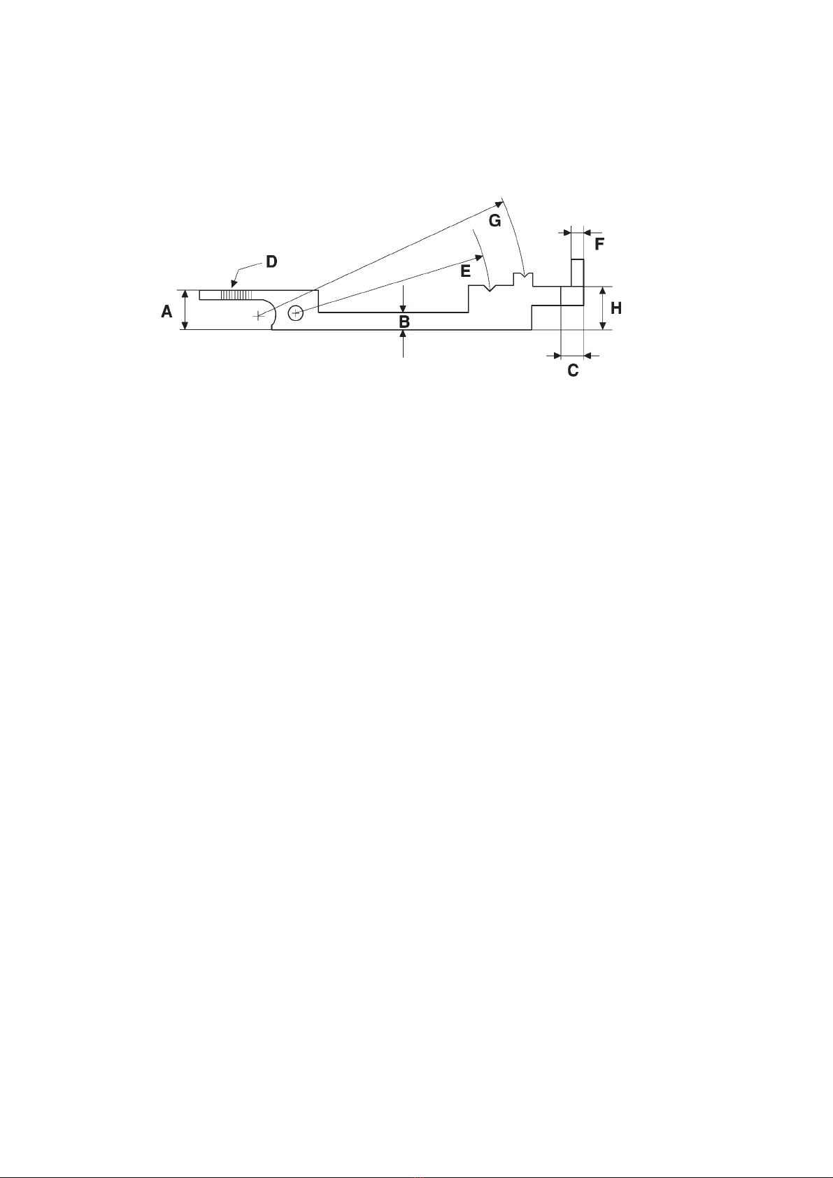
Adjustment gauge of the coverlock 4772 6
Dismantling the housing of the coverlock 4772 7
Requirements for adjusting the coverlock 4772 11
Needle bar height and needle penetration points
1. Setting the needle bar height 14
2. Setting the needle penetration points 15
Feeding system
3. Setting the main feed dog in the sewing direction with regard to the needle plate 16
4. Setting the feed dog movement 18
5. Setting the stitch length 20
6. Setting the stitch length adjustment knob 21
7. Setting the differential feed dog 22
8. Setting the differential feed-dog height 23
9. Setting the presser bar height 24
10. Setting the presser bar eccentrics 25
Setting the lower overedge looper
11. Setting the height of the lower overedge looper 27
12. Setting the timing of the lower overedge looper 28
13. Setting the looper-to-needle clearance 30
14. Setting the lateral clearance to the right needle 32
Setting the upper overedge looper
15. Setting the height of the overedge looper 33
16. Setting the lateral clearance to the right needle 34
17. Setting the timing of the upper overedge looper 35
18. Setting the clearance between the upper and lower overedge looper 36
Setting the two thread chainstitch looper
19. Setting the height of the two thread chainstitch looper 37
20. Setting the lateral clearance to the cover stitch needle (D) 38
21. Setting the looper-to-needle clearance 39
22. Setting the timing of the two thread chainstitch looper 40
Setting the needle guards
23. Setting the rear needle guard 42
24. Setting the front needle guard 43
25. Setting the needle guard for the cover stitch needles 44
Setting the upper and lower blades
26. Setting the lower blade 45
27. Setting the upper blade 46
28. Setting the lower blade bracket 47
29. Setting the chaining finger 48
Setting the looper thread guides
30. Setting the looper thread guide of the lower overedge looper 49
31. Setting the looper thread guide of the upper overedge looper 49
32. Setting the looper thread guides of the two thread chainstitch looper 50

2
Setting the thread tensions
33. Setting the release eccentric 51
34. Setting the release path of the thread tensions 52
35. Setting the release plate 53
36. Setting the thread tensions 54
37. Setting the thread check spring 55
37a. Setting the thread guide on the front housing panel 55
Repair instructions
38. Replacing the motor 56
39. Replacing the microswitch 58
Safety test
40. Electrical safety test 61
41. Electrical safety test with ABB Metrawatt M5013 62
42. Measures to be taken in the case of inadmissible test readings 65

3
Foreword
This service and repair manual is designed to help you carry out all repairs on the machine quickly and
correctly.
Adjustments should only be made if the settings deviate from the requirements described here.
When checking or adjusting a machine, always proceed in the order described here.
For easy reference every workstep is marked with a dot. Differing worksteps are marked with a circle or
square.
The indications “right”, “left”, “top”, “bottom”, “front” and “back” always refer to the upright machine with
the controls facing the operator.
When assembling dismantled machines, set the machine to approximately the right settings. This makes
any subsequent fine adjustment much easier.
Unless otherwise specified, the handwheel must always be turned to the front.
When carrying out maintenance work or when replacing mechanical parts or accessories the machine is
to be separated from the power supply by unplugging the mains plug.
An electrical safety test must be carried out following repair work, including mechanical repairs.
According to the German Machine Safety Act of 24.06.1958, VDE regulations are the recognized rules
in the field of electrical engineering and form the basis for electrical safety tests of technical appliances.
The required electrical tests for appliances are contained within the regulations for the repair, modifica-
tion and testing of used electrical appliances (VDE 0701, edition 9.71), laid out in paragraph 3.
It is obligatory to test our electrical appliances according to VDE 0701 following any repairs to our elec-
trical appliances.
Outside Germany similar regulations apply which are on the whole identical to the requirements
of VDE 0701.
Please also observe sections 40 to 42 of the adjustment and repair instructions.
Therefore a specialist must always be consulted when carrying out repairs on electrical appliances.
The microswitch must always be functionally tested following all repair work.

4
Notes on the sewing machine regarding ambient conditions, handling,
cleaning and safety
Ambient conditions:
The recommended ranges are:
Ambient temperature - 10°C to 40°C
Humidity 20 % to 80 %
This machine is a high-qulity electro-mechanical device, designed for superviced use at home.
Make sure that is not subjected to: dust, high humidity, direct sunlight, static electricity, heat-producing
objects, corrosive chemicals or liquids. The machine must be placed on a flat, stable surface allowing
good ventilation.
Handling:
Always make sure not to damage the machine by knocking or dropping it.
Cleaning:
Housing:
To clean the housing, use a dry, clean, soft, lint free cloth. To remove any stubborn stains, use a soft
cloth with a neutral cleansing agent for plastic materials.
Note:
Do not use any insecticides or chemical products such as petrol or liquid chemicals to clean the hou-
sing.
Display:
The display can be cleaned if necessary using a soft cloth moistened with a little water.
Safety:
1. The machine must be commissioned in accordance with the indications on the specification plate.
2. Do not insert any objects into the machine’s openings.
3. Do not use the sewing machine if:
- there is visible damage
- improper function
- it is wet, e.g. condensation.
4. Do not pull the mains plug out of the socket by its cord.
5. Should this appliance be used for a purpose other than intended, or if it is incorrectly operated, then
we will not accept liability for any damage caused.
6. To avoid the risk of electric shock, do not open the machine. There are no parts inside the machine
which can be repaired by the operator. This is solely the responsibility of our qualified service staff.
7. Only original PFAFF parts are to be used.

Specifications of the coverlock 4772
Number of needles and threads: 3 needles - 5, 4 or 3-thread
1 needle - 2-thread
Needles: System EL*705, cat. no. 2002
Thickness Nm 90/14
Nm 80/12
Stitch width: 3-thread: left needle 6.7 mm
right needle 4.5 mm
4-thread: 6.7 mm
5-thread: 7.7 mm
Stitch length: 1 - 4 mm adjustable
Lubrication: Manual
Differential feed: 1:0.5 ~1:2
Presser foot height: 4.5 mm
Edge-blade stroke: 7.2 mm
Sewing light: built-in 15 W
Master switch: for motor and sewing light
Motor: 110-127V including 15 W
50-60Hz 115W for the sewing light
220-240V
50-60Hz 125W
Max. sewing speed: 1300 stitches per minute
Foot control: Electronic control
Machine dimensions: Width: 300 mm, Depth: 275 mm,
Height: 285 mm
Weight: approx. 7.2 kg
5

Adjustment gauge of the coverlock 4772
Order number: 93-415 503-21/555
A= Needle bar height (10.3 mm)
B= Presser foot height (4.5 mm)
C= Clearance of upper overedge looper to right needle (4.7 - 5.0 mm)
D= Clearance of lower overedge looper to right needle (3.9 mm)
(Scale with 0.6 mm increment)
E= Height of lower overedge looper (47.6 mm)
F= Clearance of two thread chainstitch looper to needle (2.5 mm)
G= Height of two thread chainstitch looper (65.8 mm)
H= Height of upper overedge looper (10.5 mm)
6

Dismantling the housing of the coverlock 4772
● Remove the mains plug from the machine.
●Remove the fastening screw 1 (figure 1).
●Remove the presser foot holder completely.
●Remove the needles.
●Remove the detachable work support / free arm to the left (figure 2).
● Remove the fastening screw 2 (figure 3)
●Remove the spool holder completely by pushing it a little to the right and then removing it from the
rear of the machine.
● Unscrew the fastening screw 3 (figure 4).
● Remove the face cover by turning it in the direction of the arrow.
●Remove the accessory box to the left
7

●Unscrew (approx. 3 turns) and remove the fastening screw 4 using a 2 mm Allen key (figure 5).
●Remove the differential setting knob to the right (figure 6).
●Remove the small cover to the motor guard (figure 7).
●Unscrew and remove the three fastening two screws 6 to the stand cover.
● Remove the stand cover by pushing it to the back.
●Unscrew and remove the fastening screws 7 (figure 8).
●Remove the arm cover upwards.
● Unscrew and remove the light bulb.
8

● Turn the handwheel in the normal direction until the needle bar is at its highest position.
● Move the looper cover as far as possible to the right and then pull it down.
●Loosen the four fastening screws 8 of the front housing panel (figure 9).
● Unscrew and remove the fastening screw 9 and remove the cover (figure 10).
●Remove the front housing panel.
●Unscrew and remove both fastening screws 10 to the cover 11 (figure 11).
● Loosen the fastening screw 12.
●Remove the cover to the left.
●Loosen both fastening screws 13 to the rear housing panel (figure 12).
●Unscrew and remove the fastening screw 14.
● Lift the rear housing panel slightly until the locking pins are clear, then remove the housing panel.
9

●Unscrew and remove the fastening screw 15 to the microswitch housing (figure 13).
●Remove completely the microswitch housing upwards.
● Unscrew and remove the four fastening screws 16 to the baseplate (figure 14).
●Remove the machine housing carefully from the base plate.
10

11
Requirements for adjusting the coverlock 4772
Requirement 1:
For the following eccentrics the first screw must be touching the surface of the main shaft in the normal
direction (figure 1):
Stroke eccentric 1
Drive eccentric 2 for the needle bar and blade drive
When in the starting position, the first screw of the lifting eccentric 3 must be aligned with the surface of
the main shaft in the normal direction.
Note:
The lifting eccentric 3 should be set so that there is a 0.2 to 0.5 mm clearance to the feed dog carrier
(figure 2).
Requirement 2:
When the needle is at its lowest point, the lower overedge looper must be at the left point of reversal,
and the right descending looper point approx. 5 mm beneath the needle plate. The two thread chain-
stitch looper must be at its right point of reversal.
To this end, the screws of the eccentrics 4 and 6 of the looper drives must be loosened. The eccentrics
must then be turned accordingly and the screws retightened.
The drive eccentric 5 for the ellipsoidal movement of the two thread chainstitch looper is set exactly at
the factory and must only be adjusted in urgent cases.

The drive eccentric 5 for the ellipsoidal movement of the two thread chainstitch looper must be set so
that the two thread chainstitch looper 16 is in the middle of the needles “C” and “D” (fig. 2a).
Thus the screws of the drive eccentric are to be loosened.
The drive eccentric must be set in accordance with fig. 2a and the screws must be retightened.
Note:
The drive eccentric 6 for the two thread chainstitch looper is also in the basic position.
12
Requirement 3:
When the two thread chainstitch looper 16 is at the left point of reversal, the driving fork 7 of the lower
overedge looper is vertically facing upward (figure 3).
To this end, slightly loosen the fastening screw 8 of the driving crank 9.
Turn the rock shaft 10 out of position, until the driving fork 7 is vertically facing upward (figure 4).
Tighten the fastening screw 8.
There most also be a clearence of approx. 1.5 mm between the driving fork 7 and the driving crank 9,
when the driving crank is at the right point of reversal.
To this end, slightly loosen the screws 11 of the driving fork 7 (figure 3).
Move the driving fork 7 until there is a clearance of 1.5 mm.
Tighten the screws 11.

13
Note:
When the clamp cranks of the lower and upper looper lever are parallel to the main shaft, the distance
from the eccentrics 4 and 6 and the eccentric belt must be 1.0 - 1.5 mm (figure 5).
Both drive levers of the lower and upper overedge looper 12 and 13 must be positioned in a row along
the center line of the main shaft (figure 6).
The distance between the needle bar drive lever 14 and the blade drive lever 15 must be 0.5 mm
(figure 7).

Needle bar height and needle penetration points
1. Setting the needle bar height
Requirement:
The vertical clearance between the right overedge needle and the top edge of the needle plate must be
10.3 mm when the needle bar 1 is at its upper dead center (figure 1).
Check:
● Turn the handwheel in the normal direction until the needle bar 1 is at its upper dead center (u.d.c.).
● Insert the right overedge needle into the needle holder 2 as far as it will go.
● Check the needle bar height (measurement A) using the adjustment gauge.
Setting:
● Remove the face cover and the light bulb socket as described in the adjustment and repair
instructions.
● Turn the handwheel in the normal direction until the needle bar 1 is at its upper dead center (u.d.c.).
● Slightly loosen the screw 3 of the needle bar connection (figure 2).
● Move the needle bar 1 upwards without turning it until the needle touches the adjustment
gauge (measurement A).
● Tighten the screw 3.
Test:
● Check the clearance.
The needle holder must be parallel to the machine housing.
14

2. Setting the needle penetration points
Requirement:
When the needles are located in the lower dead center, the needle penetration points 4 must be cente-
red in the needle plate with a clearance of 1 mm to the front of the needle plate (figure 3).
Check:
●Turn the handwheel in the normal direction until the needle bar is at its lower dead center.
●Carry out a visual check.
Setting:
●Turn the handwheel in the normal direction until the needle bar is at its lower dead center.
●Slightly loosen the fastening screw 5.
●Turn the adjustment eccentric 6 until the needles are centered with a clearance of 1 mm to the front.
●Tighten the fastening screw 5.
Test:
●As described in “Requirement”.
Note:
Should the clearance of the two thread chainstitch needle from the needle plate be slightly off centre,
the needle holder 2 can be turned slightly (figure 1).
15

Feed system
3. Setting the main feed dog in the sewing direction with regard to the needle plate
Requirement:
When the stitch length is set to “4”, the main feed dog must be centered between the front and the back
of the needle plate in the sewing direction (figure 4).
The main feed dog must also be centered laterally.
Check:
● Loosen the screw 1 to the presser foot holder (figure 5).
●Remove the presser foot holder 2.
● Set the maximum stitch length and the standard differential stroke.
●Turn the handwheel in the normal direction until the feed dog is parallel with the upper surface
of the needle plate.
● Carry out a visual check.
Setting:
●Remove the housing cover as described in the adjustment and repair instructions.
●Set the maximum stitch length and the standard differential stroke.
● Slightly loosen both fastening screws 3 (figure 6).
●Move the feed dog carrier 4 until the feed dog is centered in the sewing direction as well
as the lateral direction.
Repeat this procedure until both settings are correct.
●Tighten the fastening screws 3.
Test:
●Check the lateral distance between the main feed dog and the needle plate.
●Check that the machine runs freely with the maximum stitch length set.
16

17

4. Setting the feed dog movement
Method:
When the rising needle leaves the fabric, the feed dog moves up above the needle plate.
The raised feed dog pushes the fabric to the rear.
After completing the feed movement the feed dog drops down below the needle plate surface and the
needle penetrates the fabric.
The feed dog returns to its starting position underneath the needle plate.
Requirement:
When the descending needle point of the needle “C” is aligned with the surface of the needle plate,
the feed dog must be in the position shown in fig. 7.
Check:
●Insert a new needle, system EL*705.
●Select the normal stitch length 3 and standard differential stroke.
● Turn the handwheel in the normal direction until the needle point of the needle “C” is flush with the
surface of the needle plate.
The feed dog should now also descend and be flush with the needle plate surface.
●Carry out a visual check.
Setting the lifting motion:
● Set the shortest stitch length and a standard differential stroke.
●Loosen the fastening screws 5 of the lifting eccentric 3 (figure 8) and rotate the eccentric
until the correct setting is reached as described under “Check”.
●Tighten the fastening screws 5 of the lifting eccentric.
Test:
● Carry out a visual check.
18

19
Other manuals for coverlock 4772
1
Table of contents
Other Pfaff Sewing Machine manuals

Pfaff
Pfaff 3811-3/55 User manual

Pfaff
Pfaff EXPRESSION 2014 User manual

Pfaff
Pfaff select 1520 User manual

Pfaff
Pfaff 300 e User manual

Pfaff
Pfaff hobbylock 2.0 User manual

Pfaff
Pfaff 245 User manual

Pfaff
Pfaff 141 User manual

Pfaff
Pfaff 130-6 User manual

Pfaff
Pfaff dorina 72 User manual

Pfaff
Pfaff hobbymatic extra 874 User manual

Pfaff
Pfaff Creative Vision User manual

Pfaff
Pfaff Creative 2134 User manual

Pfaff
Pfaff 487 User manual

Pfaff
Pfaff 3586-25 Series User manual

Pfaff
Pfaff 140S User manual

Pfaff
Pfaff 5483 Series User manual

Pfaff
Pfaff coverlock 4852 User manual

Pfaff
Pfaff Automatic 260 User manual

Pfaff
Pfaff 3511-3/01 User manual

Pfaff
Pfaff 3334 User manual