Pfaff 1591 Guide

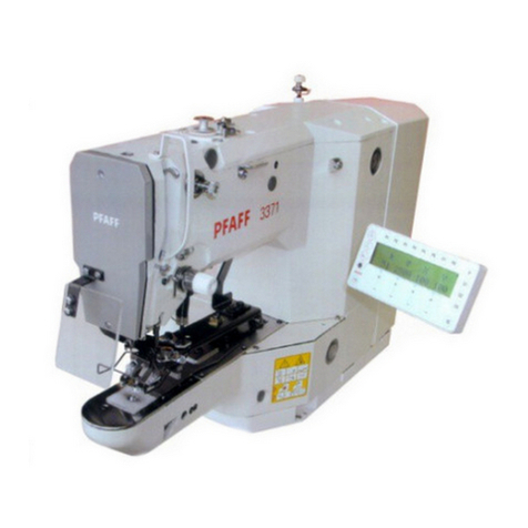
1591
1593
296-12-19 391/002
Adjustment Manual engl. 06.18
This Adjustment Manual applies to machines from the
following serial numbers onwards:
# ? ??? ???
Adjustment Manual

Reprinting, copying or translation of PFAFF instruction manuals, whether in whole or in part, is
not permitted without our prior permission and not without written indication of the source
PFAFF Industriesysteme
und Maschinen GmbH
Hans-Geiger-Str. 12 - IG Nord
D-67661 Kaiserslautern

Index
Contents ....................................................................................................Page
3
15 Adjustment ........................................................................................................................... 5
15.01 Tools, gauges and other accessories ..................................................................................... 5
15.02 Abbreviations ......................................................................................................................... 5
15.03 Explanation of symbols....................................................................................................... 5
15.04 Adjusting the basic machine............................................................................................... 6
15.04.01 Needle position in sewing direction (on the PFAFF 1591) ..................................................... 6
15.04.02 Needle position in sewing direction (on the PFAFF 1593) ..................................................... 7
15.04.03 Limiting the needle bar frame on the PFAFF 1591 ................................................................ 8
15.04.04 Preadjusting the needle height .............................................................................................. 9
15.04.05 Needle rise, hook clearance, needle height and needle guard (on the PFAFF 1591 and 1593) .10
15.04.06 Needle position crosswise to sewing direction (on the PFAFF 1591 and 1593) .................. 11
15.04.07 Height and stroke of the bobbin case opener...................................................................... 12
15.04.08 Height of the feed wheel (on the PFAFF 1591 and 1593) .................................................... 13
15.04.09 Clearance between roller presser and feed wheel .............................................................. 14
15.04.10 Roller-presser ....................................................................................................................... 15
15.04.11 Automatic presser-foot lifter................................................................................................. 16
15.04.12 Knee lever ............................................................................................................................ 17
15.04.13 Tension release .................................................................................................................... 18
15.04.14 Thread check spring (PFAFF 1511 and 1593)........................................................................ 19
15.04.15 Bobbin winder...................................................................................................................... 20
15.04.16 Roller-presser pressure ........................................................................................................ 21
15.04.17 Lubrication ........................................................................................................................... 22
15.04.18 Re-engage safety coupling................................................................................................... 23
15.05 Adjusting the edge trimmer -725/04 .................................................................................... 24
15.05.01 Position of the knife holder (on the PFAFF 1591)................................................................. 24
15.05.02 Knife stroke (on the PFAFF 1591)......................................................................................... 25
15.05.03 Cutting stroke (on the PFAFF 1591) .................................................................................... 26
15.05.04 Knife position ....................................................................................................................... 27
15.06 Adjusting the thread trimmer -900/81.................................................................................. 28
15.06.01 Resting position of the roller lever / radial position of the control cam................................ 28
15.06.02 Position of the thread catcher holder ................................................................................... 29
15.06.03 Distance between thread catcher and needle plate ............................................................ 30
15.06.04 Position of the thread catcher .............................................................................................. 31
Index
Contents ....................................................................................................Page
4
15.06.05 Knife position and knife pressure......................................................................................... 32
15.06.06 Bobbin thread retaining spring............................................................................................. 33
15.06.07 Manual cutting test .............................................................................................................. 34
15.07 Parameter settings............................................................................................................... 35
15.07.01 Overview of parameter functions ........................................................................................ 35
15.07.02 Parameter input example..................................................................................................... 36
15.07.03 Parameter list for control P320 and P321 ............................................................................ 37
15.08 Error Messages and Description.......................................................................................... 41
15.09 Warning messages .............................................................................................................. 41
15.10 Internet update of the machine software ............................................................................ 42
15.10.01 Update (with null modem cable)..........................................................................................42
15.10.02 Update (with SD card).......................................................................................................... 43
16 Circuit diagrams ........................................................................................................... 44

Adjustment
5
15 Adjustment
Please observe all notes from Chapter 1Safety of the instruction manual!
In particular care must be taken to see that all protective devices are refitted
properly after adjustment, see Chapter 1.06 Danger warnings of the instruction
manual!
If not otherwise stated, the machine must be disconnected from the electrical
power supply. Danger of injury due to unintentional starting of the machine!
Notes on adjustment
All following adjustments are based on a fully assembled machine and may only be carried
out by expert staff trained for this purpose.
Machine covers, which have to be removed and replaced to carry out checks and adjust-
ments, are not mentioned in the text.
The order of the following chapters corresponds to the most logical work sequence for
machines which have to be completely adjusted. If only specific individual work steps are
carried out, both the preceding and following chapters must be observed.
Screws, nuts indicated in brackets ( ) are fastenings for machine parts, which must be
loosened before adjustment and tightened again afterwards.
15.01 Tools, gauges and other accessories for adjusting
●Screwdrivers with blade width from 2to 10 mm
●Spanners (wrenches) with jaw width from 7to 14 mm
●1set Allen keys from 1.5to 6mm
●1metal ruler (Part no. 08-880 218-00)
●1adjustment gauge (Part No. 08-880 136-01)
●1adjustment gauge (Part No. 61-111 600-35)
●1adjustment pin (needle position in direction of sewing Part no. 61-111 641-46)
15.02 Abbreviations
t.d.c = top dead center
b.d.c = bottom dead center
15.03 Explanation of the symbols
In this adjustment manual, symbols emphasize operations to be carried out or important
information. The symbols used have the following meaning:
Note, information
Service, repair, adjustment, maintenance
(work to be carried out by qualified staff only)

Adjustment
6
2
3
1
Fig. 15 - 01
15.04 Adjusting the basic machine
15.04.01 Needle position in the direction of sewing (on the PFAFF 1591)
●Switch on the machine and set the stitch length at "5".
●Switch the machine off and on (synchronization of the needle bar to the stitch length).
●Sew one stitch and check the rear position of the needle in accordance with the require-
ment.
●Press the reverse feed key, sew one stitch and check the front position of the needle in
accordance with the requirement.
●To carry out the adjustment, loosen screw 1 through the hole on the back of the
case.•Check: Switch on the machine and choose parameter 605, turn the hand wheel
and carry out a check with the requirement.•Guide the bent part of the adjustment pin
through the elongated hole on the rear side ofthe case and insert it into hole 3 through
the hole in lever 2.•Adjust the needle bar frame 4 (screw 1) in accordance with the re-
quirement.
Screw 5 and nut 6 remain loosened for the next adjustment
Requirement
With the stitch length set at "5", in its front and rear point of reversal the needle should be
the same distance from the inside edges of the needle hole.
=
=
5
6
4

Adjustment
7
15.04.02 Positioning the needle in the direction of sewing PFAFF 1593)
Requirement
The needle must penetrate the middle of the needle hole as viewed in the direction of-
sewing.
●Move the needle bar frame 1 ( screws 2and 3 and nut 4 ) in accordance with the
requirement.
Screws 4are accessible through the holes on the back of the housing.
Fig. 15 - 02
33
2
4
1

Adjustment
8
15.04.03 Limiting the needle bar frame on the PFAFF 1591
Requirement
With the stitch length set at "5", when the needle is in its front and rear point of reversal
screw 4 should be the same distance from the inside edge of its hole.
●Switch on the machine and set the stitch length at "5".
●Sew one stitch and check the rear position of screw 4in accordance with the requirement.
●Operate the reverse feed key, sew one stitch and check the front position of screw 4in
accordance with the requirement.
●To carry out the adjustment shift plate 1(screw 2and nut 3) in accordance with the re-
quirement.
Fig. 15 - 03
==
4
1
4
3
2

Adjustment
9
15.04.04 Preadjusting the needle height
Requirement
With the needle bar at TDC there must be approx. 21 mm between the point of the need-
le and the needle plate.
●Move the needle bar 1 ( screw 2) in accordance with the requirement without turning it.
Fig. 15 - 04
21 mm
1
2

Adjustment
10
15.04.05 Needle rise, hook clearance, needle height and needle guard (on the PFAFF 1591 and 1593)
Regel
With the needle bar positioned 2.0 mm after BDC and the stitch length set at "0.8"( only
on the PFAFF 1591).
1. the hook point must be at needle centre with a hook-to-needle clearance of 0.05 to
0.1 mm;
2. the top of the needle eye must be 0.8 to 1.0 mm below the hook point;
3. the needle guard 6must touch the needle lightly.
Fig. 15 - 05
6
9
4
5
5
1
4
3
78
2
●Set stitch length at "0.8".(only on the PFAFF 1591).
●Loosen both screws 1, 2, 3, 4 and 5.
●Bring the needle bar to 2.0mm after b.d.c. and place the locking pin for the needle bar
●Set the hook point to the centre of the needle, taking care to see that the needle is not
deflected by needle guard 6.
●Adjust needle height according to Requirement 2.
●Adjust hook post according to Requirement 1and tighten screws 4and 3.
●Making sure that there is some play in the bevel gear, tighten screws 2.
●With retaining collar 7 touching bevel gear 8 tighten screws 2 and 3.
●Screws 5remain loose for further settings.
●Adjust needle guard 6(screw 9) in accordance with requirement 3.
When the hook is changed, make sure that the markings 10 and 11 are both on
one side.
0,8 - 1 mm
10
11

Adjustment
11
15.04.06 Needle position crosswise to sewing direction (on the PFAFF 1591 and 1593)
Requirement
As seen crosswise to the sewing direction, the needle must penetrate in the centre of the
needle hole.
●Adjust feed wheel post 1(screws 2, 3 and 4) according to the requirement.
Fig. 15 - 06
3
1
2
4
4
4
2

Adjustment
12
15.04.07 Height and stroke of the bobbin case opener
Requirement
1. The top edges of the bobbin case opener 1 and bobbin case base 3 should be on onelevel.
2. When the bobbin case opener 1has deflected the bobbin case to its furthest point,
thecatch of the bobbin case should be 0.3- 0.5mmfrom the back edge of the needle-
plate recess.
●Adjust bobbin case opener 1(screw 2) in accordance with requirement 1.
●Turn the balance wheel until the bobbin case opener has deflected the bobbin case to its-
furthest point.
●Adjust bobbin case opener 1(screw 2) in accordance with requirement 2.
Depending on the thread size, a variation of the setting in Requirement 2isper-
mitted.
1
2
Fig. 15 - 07
3
1
0,3 - 0,5 mm

Adjustment
13
15.04.08 Height of the feed wheel (on the PFAFF 1591 and 1593)
Requirement
The feed wheel should protrude from the needle plate by tooth height (approx. 0.8mm)
●Swing out the roller presser.
●Loosen screws 1.
●Adjust eccentric 3(fastening screw accessible through hole 2) according to the require-
ment.
●Tighten screws 1.
Fig. 15 - 08
1
32
0,8 mm

Adjustment
14
●Raise lever 1.
●Move the presser foot bar ( screws 2) in accordance with the requirement. Take care to-
ensure that the roller presser is parallel to the feed wheel.
15.04.09 Clearance between roller presser and feed wheel
Requirement
With lever 1raised the clearance between the roller presser and the feed wheel must be
7mm.
Fig. 15 - 09
1
2
7 mm

Adjustment
15
15.04.10 Roller-presser
●Raise the roller-presser 1.
●Always observe requirement 1when carrying out the following adjustments.
●Move the roller-presser 1( screw 2) in accordance with requirement 2.
●Rollfuß 1auf das Schiebrad 5aufsetzen lassen.
●Move the roller-presser bracket 3( screw 4) in accordance with requirement 3.
When sewing very tight curves the roller-presser 1 should be moved toward the-
operator slightly.
Requirement
When the roller-presser 1is resting on the feed wheel 5it must
1. be parallel to the feed wheel 5 when viewed in the direction of sewing,
2. be in the middle of the needle when viewed crosswise to the direction of sewing and
3. be as close as possible to the ( left ) needle when viewed in thedirection of sewing.
4
2
3
15
Fig. 15 - 10

Adjustment
16
15.04.11 Automatic presser-foot lifter
Requirement
When solenoid 1 is activated, lever 3 for the roller-presser must drop automatically.
●Move solenoid 1( screws 2) in accordance with the requirement.
●Turn the machine on and check the requirement.
●Turn the machine off.
Depending on the thickness of the material, the clearance between the roller-presser
and the feed wheel can be increased to a maximum of 11 mm by moving the sole-
noid 1to the right.
1
2
Fig. 15 - 11
63-020
3
75°

Adjustment
17
15.04.12 Knee lever
Requirement
1. The knee lever must have a little play before the roller-presser is raised.
2. The lever for the roller-presser must drop automatically when the knee lever is presse-
das far as it will go.
3. Bar 5of the knee lever must be at an angle of approx. 75° to the bedplate.
●Turn screw 1( nut 2) in accordance with requirement 1.
●Turn screw 3( nut 4) in accordance with requirement 2.
●Adjust bar 5( screw 6) in accordance with requirement 3.
Fig. 15 - 12
1
2
3
4
5
6
75°

Adjustment
18
15.04.13 Tension release
Requirement
The two tension disks 8should be at least 0.5 mm apart
1. when lever 1is raised,
2. when the automatic presser foot lift is operated or
3. when solenoid 6is pressed.
●Raise lever 1and adjust screw 2(nut 3) in accordance with requirement 1.
●Raise the roller presser with the automatic presser foot lift or with the knee lever andad-
just catch 4(screw 5) in accordance with requirement 2.
●Press solenoid 6as far as possible.
●Adjust solenoid 6(screws 7) in accordance with requirement 3.
The point of time when the tensioned is released by solenoids 6can be set with-
the service functions, see Chapter 15.07 Parameter settings.
Fig. 15 - 13
0,5 mm
8
3
2
4
5
17
6

Adjustment
19
15.04.14 Thread check spring (on the PFAFF 1591 and 1593)
Requirement
1. The movement of thread check spring 3should be completed when the needle point-
penetrates the fabric (spring stroke approx. 7 mm).
2. When the largest thread loop is formed while the thread is passed around the
hook,the thread check spring 3should rise slightly from its support 1.
●Adjust support 1(screw 2) according to requirement 1.
●To adjust the spring tension of spring 3turn bushing 4(screw 2).
●Adjust the thread regulator 5(screw 6) according to requirement 2.
For technical reasons it may be necessary to deviate from the specified
springstroke or spring tension.Move the thread regulator 5(screw 6) towards
"+" (= more thread) or "-" (= lessthread).
Fig. 15 - 14
6
5
32
41

Adjustment
20
15.04.15 Bobbin winder
●Position drive wheel 1(screws 2) according to requirement 1.
●Position bolt 3(screw 4) according to requirement 2.
Requirements
1. When the bobbin winder is engaged, the winding spindle must be driven reliably. When the
bobbin winder is disengaged, the friction wheel 5must not be moved by drive wheel 1.
2. The bobbin winder must switch itself off, when the filled thread is about 1 mm from-
the edge of the bobbin.
1
2
5
Fig. 15 - 15
3
4
Other manuals for 1591
1
This manual suits for next models
1
Table of contents
Other Pfaff Sewing Machine manuals

Pfaff
Pfaff 1025 User manual

Pfaff
Pfaff creative 4874 User manual

Pfaff
Pfaff 1211 User manual

Pfaff
Pfaff smart 100s User manual

Pfaff
Pfaff creative 2170 Guide

Pfaff
Pfaff 3822-1/32 User manual

Pfaff
Pfaff Hobbylock 4860 User manual

Pfaff
Pfaff 1425 User manual

Pfaff
Pfaff select 2.0 User manual

Pfaff
Pfaff select 8.0 User manual

Pfaff
Pfaff 9371-SPS User manual

Pfaff
Pfaff Tiptronic 6230 User manual

Pfaff
Pfaff 1295 Guide

Pfaff
Pfaff 131 User manual

Pfaff
Pfaff 3586-2/02 User manual

Pfaff
Pfaff 3371-1 series User manual

Pfaff
Pfaff hobbylock 4760 User manual

Pfaff
Pfaff 333-712/02 User manual

Pfaff
Pfaff hobbyblock 794 User manual

Pfaff
Pfaff PowerLine 2231 Manual