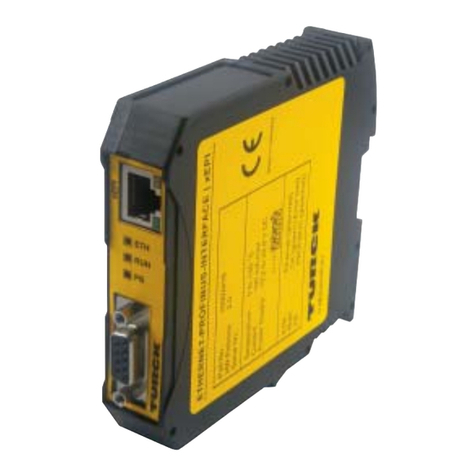
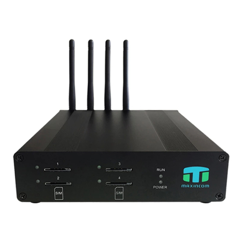
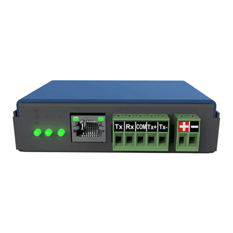
Pfeiffer Vacuum TIC 253 User manual

Betriebsanleitung • Operating Instructions
PT0138BE/A (0507)
TIC 253
TIC 254
Profibus-DP gateway for
TCP 350 and TCP/TM 3000

2
Inhalt
Inhalt
Hinweis! Aktuelle Betriebsanleitungen sind auch über
das Internet unter www.pfeiffer-vacuum.net verfügbar.
1. Safety Precautions 3
1.1 Pictogram Definitions . . . . . . . . . . . . . . . . . . . . . . . . . . . . . . . . . . . . . . . . 3
1.2 For Your Orientation . . . . . . . . . . . . . . . . . . . . . . . . . . . . . . . . . . . . . . . . . 3
2. Product Description 4
2.1 Delivery . . . . . . . . . . . . . . . . . . . . . . . . . . . . . . . . . . . . . . . . . . . . . . . . . . . 4
2.2 Proper Use . . . . . . . . . . . . . . . . . . . . . . . . . . . . . . . . . . . . . . . . . . . . . . . . 4
2.3 Improper Use . . . . . . . . . . . . . . . . . . . . . . . . . . . . . . . . . . . . . . . . . . . . . . 5
3. Installation 6
3.1 Preparations For Installation . . . . . . . . . . . . . . . . . . . . . . . . . . . . . . . . . . . 6
3.2 Profibus Connection . . . . . . . . . . . . . . . . . . . . . . . . . . . . . . . . . . . . . . . . . 6
4. Operation 8
5. Modules 9
5.1 Module 1: "standard" . . . . . . . . . . . . . . . . . . . . . . . . . . . . . . . . . . . . . . . . 10
5.2 Module 2: "power" . . . . . . . . . . . . . . . . . . . . . . . . . . . . . . . . . . . . . . . . . .11
5.3 Module 3: "ophrs_pump" . . . . . . . . . . . . . . . . . . . . . . . . . . . . . . . . . . . . .11
5.4 Module 4: "ophrs_drv" . . . . . . . . . . . . . . . . . . . . . . . . . . . . . . . . . . . . . . . 11
5.5 Module 5: "tms" . . . . . . . . . . . . . . . . . . . . . . . . . . . . . . . . . . . . . . . . . . . . 12
5.6 Module 6: "venting" . . . . . . . . . . . . . . . . . . . . . . . . . . . . . . . . . . . . . . . . . 12
5.7 Module 7: "fixed_value_out" . . . . . . . . . . . . . . . . . . . . . . . . . . . . . . . . . . 12
5.8 Module 8: "fixed_value_in". . . . . . . . . . . . . . . . . . . . . . . . . . . . . . . . . . . .13
5.9 Module 13: "fail_safe" . . . . . . . . . . . . . . . . . . . . . . . . . . . . . . . . . . . . . . . 13
5.10 Module 14: "acyclic access". . . . . . . . . . . . . . . . . . . . . . . . . . . . . . . . . . . 14
6. Extended Diagnosis Data 15
7. What To Do In Case Of Breakdowns? 15
8. Maintenance And Service 16
9. Technical Data 16
10. Accessories 16
11. Valid Parameters 17
11.1 Caption for List of Valid Parameters . . . . . . . . . . . . . . . . . . . . . . . . . . . . 18

3
Safety Precautions
1. Safety Precautions
☞Read and follow all the instructions in this manual.
☞Inform yourself regarding:
– Hazards which can be caused by the unit,
– Hazards which can arise in your system.
☞Comply with all safety and accident prevention regulations.
☞Check regularly that all safety requirements are being complied with.
☞Take account of the ambient conditions when installing the TIC 253/254.
– The protection type of the TIC 253/254 is IP20/IP 54 when assembling accurate.
☞Do not carry out any unauthorised conversions or modifications on the unit.
☞Do not open the housing cover when the unit is connected to the mains nor during
pumping operation.
☞Take account of the prescribed voltage when connecting the cable to the various
plugs.
☞When returning the unit to us please note the shipping instructions.
1.1 Pictogram Definitions
1.2 For Your Orientation
Operating Instructions In The Text
➡Here, you have to do something!
Caution
Caution, danger of damage to the pump or system.
Please note
☞
Attention to particularly important information on the pro-
duct, handling the product, or to a particular part of the
documentation.

4
Product Description
2. Product Description
The TIC 253 respectively TIC 254 provides a connection for the bus system Profibus-DP
(V0) for the drive units TCP 350 and TCP 3000 respectively TM 3000. If not stated other-
wise the designation "TIC" applies to the TIC 253 and also to the TIC 254.
Abb. 2-1 Description of the front panel
Connection options The TIC offers connection options for the Profibus-DP by means of a 9-way Sub-D sok-
ket (TIC 253) respectively by means of two B-coded M12 connectors (TIC 254).
2.1 Delivery
Included with the delivery of the TIC 253/254 are the following items:
• Unit TIC 253 respective TIC 254
• CD with GSD file and graphics for inclusion in the Profibus configuration tool.
2.2 Proper Use
The TIC serves the purpose of connecting the aforementioned drive units to the Profi-
bus-DP (V0). The type of protection stated for the TIC 254 can only be attained in the
case of correctly fitted rubber stoppers to the address selector switches and the service
connection as well as with connected Profibus connectors, respectively connector with
terminating resistor.
1
1
2
5
3
4
3
4
1
2
TIC 253
TIC 254
➀Profibus-DP connection
➁Status display
➂Profibus-DP Address
(hexadecimal, most significant bit „msd“)
➃Profibus-DP Address
(hexadecimal, least significant bit „lsd“)
➄Service connection

5
Product Description
2.3 Improper Use
Improper is:
– Uses not covered above, and, in particular,
– Connection to pumps and units which is not permitted in their operating instruc-
tions.
– Connection to units which contain touchable and voltage carrying parts.
Improper use will cause any rights regarding liability and guarantees to be forfeited.

6
Installation
3. Installation
3.1 Preparations For Installation
➡Connect the Profibus cable to the TIC and secure it against inadvertent loosening by
screwing it down. When doing so, note the applicable regulations and recommenda-
tions for installing a Profibus system.
➡Set the address selector switch to the Profibus address intended for this instru-
ment.
➡TIC 254: fit the rubber stoppers to the address selector switches so as to attain the
type of protection stated. The stoppers must be inserted straight and as deeply as
possible into the holes.
➡To configure the TIC use the enclosed GSD file. Information on this can be found
with your Profibus configuration tool and in the see Chap. 5., page 9.
3.2 Profibus Connection
The Profibus is connected to this box. The pin arrangement is in accordance with the
Profibus standard. Thereby the functions are supported in accordance with the pin assi-
gnment in the table below. It is recommended to tighten the securing screws of the plug
to prevent unintentional disconnection of the plug.
TIC 253 Pin Function
1Shield
2-
3 RxD/TxD-P
4CNTR-P
5 DGND
6VP
7-
8 RxD/TxD-N
9-
TIC 254 Pin Function
plug
socket
1VP
2 RxD/TxD-N
3DGND
4 RxD/TxD-P
5 Shield
Socket and plug are wired in
parallel so that they provide the
same functions.
For the Profibus connection of the TIC 254 you may use
the kits listed as accessories, see Chap. 10., page 16
Tabelle 3.2.1: Pin assignment Profibus connector
9
8
7
6
5
4
3
2
1
5
2 1
3 4
5
1 2
4 3

7
Installation
Address Selector Switch The Profibus address is set up with the address selector switch using hexadecimal co-
ding. For conversion of decimal to hexadecimal addresses please refer to Table 3.2.2 on
page 7.
➡TIC 254: Fit the rubber stoppers to the address selector switches so as to attain the
type of protection stated. The stoppers must be inserted straight and as deeply as
possible into the holes.
Tabelle 3.2.2: Profibus-DP address (hexadecimal): Conversion to decimal data
➂➃ Adr. ➂➃ Adr. ➂➃ Adr. ➂➃ Adr. ➂➃ Adr. ➂➃ Adr. ➂➃ Adr. ➂➃ Adr.
hex. dez. hex. dez. hex. dez. hex. dez. hex. dez. hex. dez. hex. dez. hex. dez.
00 0 10162032304840645080609670112
01 1 11172133314941655181619771113
02 2 12182234325042665282629872114
03 3 13192335335143675383639973115
04 4 142024363452446854846410074116
05 5 152125373553456955856510175117
06 6 162226383654467056866610276118
07 7 172327393755477157876710377119
08 8 182428403856487258886810478120
09 9 192529413957497359896910579121
0A 10 1A 26 2A 42 3A 58 4A 74 5A 90 6A 106 7A 122
0B 11 1B 27 2B 43 3B 59 4B 75 5B 91 6B 107 7B 123
0C 12 1C 28 2C 44 3C 60 4C 76 5C 92 6C 108 7C 124
0D 13 1D 29 2D 45 3D 61 4D 77 5D 93 6D 109 7D 125
0E 14 1E 30 2E 46 3E 62 4E 78 5E 94 6E 110 7E 125
0F 15 1F 31 2F 47 3F 63 4F 79 5F 95 6F 111 7F 125

8
Operation
4. Operation
Before operating the TIC for the first time the valid and unique serial interface address
has to be set by means of the Profibus address selection switch. Alterations to the
address during operations are not permissible.
Illuminating Displays
This LED provides information on the general unit status and the communication with
the TIC unit. Upon switching on there is a test phase of approximately one second for
the LED. Only thereafter will the Table 4.0.1 on page 8 be valid.
Please note
☞
In the case of the TCP 350 (TIC 253) the time which elapses between switching on the
instrument until the Profibus is available may amount to approximately
15 seconds!
Status Definition
Off Unit is not supplied with adequate voltage
Green illuminating Communication with the TIC unit running (status
data_exchange)
Green flashing Bus traffic detected, no data_exchange
Green 1 x short, 1 x long flashing The set address is not the one with which the unit is
currently working Abb. 2-1, Page 4
Red illuminating Unit defective
Red flashing No bus traffic detected
Red 1 x short, 1 x long flashing Current parameter data are erroneous
Red 2 x short, 1 x long flashing Current configuration data are erroneous
Tabelle 4.0.1: Illuminating Displays

9
Modules
5. Modules
Select the modules depending on which data you want to exchange with the drive unit.
➡Thereby configure module modul 1 always first and use only once. As to restrictions
of the parameter values and parameter numbers please refer to the Operating
Manuals of the drive units used.
➡Please also note the following:
Tabelle 5.0.1: Modules overview
Output data:
Contains data from the master (e.g. PLC) to the TIC.
Input data:
Contains data from the TIC to the master (e.g. PLC).
Configuration data:
Contains identification of the module.
Parametering data:
Contains additional module-specific information.
PLEASE NOTE
☞
– A maximum of 18 modules can be used.
– In the input data of the modules a maximum of 42 parameters may be present
[Pxxx].
– In the configuration no other module may be present after the "fail_safe" mo-
dules.
– In order to update the input data as rapidly as possible, please use only the mo-
dules you really require and do not use multiple parameter numbers.
– Access to the functions in the modules can be influenced by external circuitry
of the drive unit used (refer to the Operating Manual of the drive unit).
# Modules Description I- O-
Data (Byte)
1 standard Standard functions 4 3
2 power Current and Voltage 4 0
3 ophrs_pump Operating hours pump 4 0
4 ophrs_drv Operating hours drive 4 0
5 TMS TMS heating 1 1
6 venting Venting 0 3
7 fixed_value_out 1 parameter value output 0 2
8 fixed_value_in 1 parameter value input 2 0
13 fail_safe Behaviour if communication fails 0 0
14 acyclic access acyclic access 12 8

10
Modules
5.1 Module 1: "standard"
This module must always be configured first and must be used only once.
Output data:
a: Pre-selection heating [P001]: 0 – off, 1 – on
b: Stand by [P002]: 0 – off, 1 – on
c: Error acknowledgement [P009]: only when a malfunction is present to 1, otherwise
0
d: Pumping station [P010]: 0 – off, 1 – on
e: Motor [P023]: 0 – off, 1 – on
f: Operating mode pump [P026]: 0 – final rotation speed mode, 1 – rotation speed set-
ting mode (see pos. h:)
g: Run-up time monitoring [P004]: 0 – off, 1 – on
h: Set rotation speed as a % of the final rotation speed [rounded P707], only then
valid in rotation speed setting mode (f: is switched to 1)
i: Rotation speed switch point as a % of the final rotation speed [P701]
Input data:
a: Unit remote controlled [P300]: 0 – no, 1 – yes
b: Switchpoint attained [P302]: 0 – no, 1 – yes
c: Set rotation speed attained [P306]: 0 – no, 1 – yes
d: Pump accelerates [P307]: 0 – no, 1 – yes
e: TMS controller responded [P333]: 0 – no, 1 – yes
f: Actual rotation speed as a % of the final rotation speed
g: Error/Warning number (low byte): 0 – no error, 1...999 – error 1...999, 1001...1999 –
warning 1...999
h: Error/Warning number (high byte)
i: Oil deficiency
j: Excess temperature [P304, P305]: 0 – no, 1 – yes
Configuration data:
C1h, 02h, 83h, 01h
PLEASE NOTE
☞
The fields "h" and "i" must always be filled with valid values (for example 50), even though
these functions are not used.
Byte 012
Bit 76543210
abcdefg - h i
Byte 012 3
Bit 76543210 765 4... 0
abcde - - - f g i j - h

11
Modules
5.2 Module 2: "power"
This module may only be used a maximum of once.
Input data:
Configuration data:
41h, 41h, 02h
5.3 Module 3: "ophrs_pump"
This module may only be used a maximum of once.
Input data:
Configuration data:
41h, 83h, 03h
5.4 Module 4: "ophrs_drv"
This module may only be used a maximum of once.
Input data:
Configuration data:
41h, 83h, 04h
Byte 0123
Current in 10 mA [P310] Voltage in 10 mV [P313]
low byte high byte low byte high byte
Byte 012 3
Operating hours of the pump [P311]
low word /
low byte
low word /
high byte
high word /
low byte
high word /
high byte
Byte 012 3
Operating hours of the electronic drive unit [P314]
low word /
low byte
low word /
high byte
high word /
low byte
high word /
high byte

12
Modules
5.5 Module 5: "tms"
This module may only be used a maximum of once.
Output data:
Input data:
Configuration data:
C1h, 00h, 00h, 05h
5.6 Module 6: "venting"
This module may only be used a maximum of once.
Output data:
Configuration data:
81h, 82h, 06h
5.7 Module 7: "fixed_value_out"
With this module an additional parameter can be described the parameter number of
which is stated in the parameter data (low byte first). The output data must then contain
a valid setpoint. For possible parameters see Chap. 11., page 17.
Output data:
Configuration data:
81h, C0h, 07h
Parametering data:
Byte 0
Set value TMS heating in °C [P704]
Byte 0
Actual value TMS heating in °C [P331]
Byte 012
Venting frequency as a
% of the final rotation
speed [P720]
Venting time in s [P721]
low byte high byte
Byte 01
Parameter value
low byte high byte
Byte 01
Parameter number
low byte high byte

13
Modules
5.8 Module 8: "fixed_value_in"
With this module an additional parameter can be read the parameter number of which
is stated in the parameter data (low byte first). The input data then contain the current
value. As to the possible parameters see Chap. 11., page 17.
Input data:
Configuration data:
41h, C0h, 08h
Parametering data:
5.9 Module 13: "fail_safe"
Through this module you can state which actions the TIC shall perform in the Profibus
status „fail_safe“, for example switch pump off in case the Profibus connection fails. In
the parameter data, the parameter number and the parameter value are stated which
shall be written in this case. As to the possible parameters see Chap. 11., page 17. This
module can be used up to four times in the configuration.
Configuration data:
00h
Parametering data:
Byte 01
Parameter value
low byte high byte
Byte 01
Parameter number
low byte high byte
Please note
☞
Please note that your Master may possibly attain during starting of the Profibus the sta-
tus "fail_safe" and that because of this these modules are run.
Byte 0123
Parameter number Parameter value
low byte high byte low byte high byte

14
Modules
5.10 Module 14: "acyclic access"
This module may be used for acyclic accesses. In the output data the command, the
path and possibly necessary data is output. After running, the input data contain the con-
firmation of the command, the path and possible additional information. Data is only ex-
changed in case the output data change.
Output data:
a: Service – e.g. read or write (see Chap. 11., page 17)
b: Path (see Chap. 11., page 17)
d0...d3: Data (don’t care on read access), format see Chap. 11., page 17
Input data:
a: Contains field a of output data with Bit 6 set (e.g.: 1 --> 65) on correct execution, on
error value 71.
b: Path, repeats path in output data
d0...d7: Data (don’t care on write access), format see Chap. 11., page 17
Configuration data:
C1h, 87h, 8Bh, 0Eh
Byte 01234567
a b d0 d1 d2 d3
Byte 012 3 4 5 6 7 891011
a b d0 d1 d2 d3 d4 d5 d6 d7

15
Extended Diagnosis Data
6. Extended Diagnosis Data
a: Laid down via the Profibus standard
b: General status of the TIC and of the connected drive unit:
c: d1...dx: Number of the 1., ... x. Module
d: e1...ex: Status of the 1., ... x. Module
7. What To Do In Case Of Breakdowns?
Byte 0 1 2 3 4 5 6 7 8 9 10 ... n-2 n-1
a b c d1 e1 ... dx ex
Byte 78
Bit 76543210
Error number drive
unit, Bit 3-0
TIC status
(0: ok,≠0: internal
error)
error number drive unit,
Bit 11-4
Status Meaning
0No module assigned
1Module status OK
2At least one parameter which is assigned to this module is not supported by the
connected electronic drive unit.
3The Parameter number selected in this module does not exist
4The transmitted parameter value in this module is outside the valid range.
5
An access logic error has occurred in this module: it has been attempted to write
to a parameter which is only readable or a parameter value to read which is only
writeable.
6This module does not support the data type of the addressed parameter.
7The "standard module" is not located in the first connection slot
8An error has been acknowledged although no error has occurred.
9The maximum number of permissible "fail_safe modules" has been exceeded.
10 Unknown module
13 The maximum permissible number of the requested parameter numbers has been
exceeded.
14 Modules which may use once, are used multiple.
15 This module cannot be used for the connected drive unit.
Tabelle 6.0.1: Module regarded error numbers
Problem Possible Reasons Resolution
Parametrization error
Low and high byte of the parameter
number is interchanged in the modules
fixed_value_in or –out
The parameter numbers are stated with
the low byte first.
Read data not plausible Low and high byte, respectively word of
the data is interchanged
The data is transmitted with the low
bite/word first.
Instrument or entire branch is not visible
on the Profibus Terminating resistor switched on
The terminating resistor may only be
switched on at the beginning and the
end of the bus, but not in the case of an
instrument in between.

16
Maintenance And Service
8. Maintenance And Service
The unit requires no maintenance. A damp cloth can be used to wipe away any dirt
which has collected on the front panel. Ensure that the unit is first disconnected from
the mains power supply.
Do Make Use Of Our Service Facilities!
In the event that repairs are necessary a number of options are available to you to ensure
any system down time is kept to a minimum:
• Return the unit to the manufacturer for repairs;
• Replace with a new value unit.
Local Pfeiffer Vacuum representatives can provide full details.
9. Technical Data
10. Accessories
CAUTION
The unit is not prepared for customer repair.
Units returned to us for repair or maintenance are covered by our general conditions of
sale and supply. Please refer to the back cover of this manual for contact addresses and
telephone hotline numbers
Description Unit TIC 253 TIC 254
Profibus version DP-V0
Baud rates baud 9,6 k; 19,2 k; 45,45 k; 93,75 k; 187,5 k; 500 k;
1,5 M; 3 M; 6 M; 12 M
Permissible ambient temperature °C 5 – 40
Max. relative humidity (non condensing) % (at 5 – 40 °C) 5 – 85
Air pressure kPa 86 – 106
Protection type IP 20 IP 54
Designation Number
Profibus connectors (male and female) M12B PM 051 927 -T
Profibus connector (female) and termination resistor M12B PM 051 928 -T

17
Valid Parameters
11. Valid Parameters
#Name
TCP 350
TCP 3000
TM 3000
contained
usable
in module
Pos. in I-/O data in module 14
(decimal)
7813a b dataformat
1 Preselection heating ●●
1●●●➏6, 2, 16 byte
2Standby ●●● 1●●●➏4, 1, 28 byte
4 Startup time monitoring ●●● 1●●●➏5, 1, 20 byte
8 Keyboard interlock ●● ●●●➏9, 1, 16 byte r
9 Error acknowledgement ●●● 1●63,1,0 -
10 Pumping station ●●● 1●●●➏5, 1, 16 byte
12 Venting release ●●● ●●●➏6, 4, 16 byte
13 Preselection brake ●●●●➏6, 3, 16 byte
19 Configuration switch output K2 ●●● ●●●➏9, 5, 17 byte
23 Motor TMP ●●● 1●●●➏4, 1, 30 byte
24 Configuration switch output K1 ●●●●➏9, 4, 17 byte
25 Operating mode BKP ●● ●●●➏6, 1, 17 byte
26 Operating mode TMP ●●● 1●●●➏4, 1, 23 byte
27 Gas mode ●●● ●●●➏4, 1, 21 byte
28 Operating mode remote ●●● ●●●➏9, 2, 17 byte
29 Operating mode drive unit ●●●●➏4, 1, 19 byte
30 Venting mode ●●● ●●●➏6, 4, 17 byte
50 Direct control seal gas valve ●●●●➏6, 6, 16 byte
52 Gas ballast valve ●➏6, 9, 17 byte
55 Configuration analog output 1 ●●● ●●●➏9, 10, 17 byte
95 Factory setting ●● ● 22 1, 1, 0 0
300 Unit remote controlled ●●● 1●19,2,18 byte
301 Oil deficiency TMP ●● 113,1,17 wordt
302 Rotation speed switch point attained ●●● 1●15,1,18 byte
303 Actual error code ●●● 1●13,1,18 wordu
304 Over temperature drive unit ●●● 113,1,17 wordt
305 Over temperature TMP/BKP ●●● 113,1,17 wordt
306 Set rotation speed attained ●●● 1●1 4, 1, 25 byte v
307 Pump accelerates ●●● 1●1 4, 1, 25 byte v
308 Set rotation speed (Hz) ●●● ● 1 4, 1, 27 dword
309 Actual rotation speed (Hz) ●●● 1➋ ●1 4, 1, 22 dword
310 Motor current (10 mA) ●●● 2●14,1,17 real
w
311 Operating hours pump (h) ●●● 3➌1 4, 1, 31 dword
312 Software version drive unit ●●● 1 1, 1, 23 byte u
313 Motor voltage (10 mV) ●●● 2●14,1,16 realw
314 Operating hours drive unit (h) ●●● 4➌1 1, 1, 30 dword
315 Final rotation speed (Hz) ●●● ● 1 4, 1, 26 dword
316 Motor power (W) ●●● ● 14,1,18 real
319 Cycle counter ●●● ➌1 5, 1, 19 dword
323 Temperature cooling plate ●●1 1, 1, 31 word u
329 Fanglagerverschleiß ●●1 4, 1, 34 word
331 Heating TMS, actual value ●5●16,2,19 word
333 TMS controller steady state ●1●16,2,18 byte
334 Max TMS temperature occurred ●●1 6, 2, 22 word
335 Heating type ●● ● 1 6, 2, 23 byte
346 Motor temperature ●● ● 1 4, 1, 32 word u

18
Valid Parameters
11.1 Caption for List of Valid Parameters
349 Unit type drive unit ●●● 11,1,17 byte
u
352 Software version motor controller ●●● 1 1, 2, 23 byte u
354 Hardware version ●●● 1 1, 1, 22 byte u
357 CPLD Version ●1 1, 2, 22 byte u
358 Out-of-balance amplitude A ●●
1 4, 1, 33 byte u
359 Out-of-balance amplitude B ●●
360 Malfunction memory, position 1 ●●● ● 13,2,18 word
u
361 Malfunction memory, position 2 ●●● ● 13,3,18 word
u
362 Malfunction memory, position 3 ●●● ● 13,4,18 word
u
363 Malfunction memory, position 4 ●●● ● 13,5,18 word
u
364 Malfunction memory, position 5 ●●● ● 13,6,18 word
u
365 Malfunction memory, position 6 ●●● ● 13,7,18 word
u
366 Malfunction memory, position 7 ●●● ● 13,8,18 word
u
367 Malfunction memory, position 8 ●●● ● 13,9,18 word
u
368 Malfunction memory, position 9 ●●● ● 13,10,18word
u
369 Malfunction memory, position 10 ●●● ● 13,11,18 word
u
700 Max. run-up time ●●● ● ● ● ➏ 5, 1, 21 byte
701 Switchpoint in % of final rotation speed ●●● 1●●●➏5, 1, 17 byte
704 TMS heating set value in °C ●5●●●➏6, 2, 20 word
707 Rotation speed set value in rot. speed set-
ting mode ●●● 1n❹❹❹➏4, 1, 24 real
710 Poff for VVP interval operation in W ●● ●●●➏6, 1, 21 word
711 Pon for VVP interval operation in W ●● ●●●➏6, 1, 22 word
717 Standby frequency ●●● ❹❹❹➏4, 1, 29 real
720 Venting frequency ●●● 6●●●➏6, 4, 22 dword
721 Venting time ●●● 6●●●➏6, 4, 20 word
777 Set value max. pump rotation speed ●●● ● ● 24 4, 1, 26 word
794 Parameter set ●● ➏ 9, 11, 16 byte
795 Service line ●● ➏ 9, 11, 17 word
797 Unit address ●●● ● ● ● ➏ 9, 12, 19 byte
➊in %
➋in % (with respect to [P315])
➌only valid to 65535
➍in 0.01 %
➎0: blocked, 1: released
➏Command 1: read 2: write
Comment
Data field in the output data is
not used. The column "Data"
describes the format in the
data field of the input data.
The column "Data" describes the
format of the information to be sta-
ted in the output data.
Example
Read standby:
A-data: 1, 4, 1, 28
--> E-data 65, 4, 1, 28, 0
(standby is off)
Switch standby on:
A-data: 2, 4, 1, 28, 1
--> E-data 66, 4, 1, 28 (ok)
Tabelle 11.1.1: Caption for List of Valid Parameters

19
Valid Parameters
The data appear left aligned in the corresponding data fields, excess digits are of no si-
gnificance. The following formats are possible:
– byte: 1 byte
– word: 1 word (d0 = low byte, d1 = high byte)
– dword: 1 double word (4 Byte, low byte/word first)
– real: Floating point number in accordance with IEEE 754 (4 bytes, low byte
first)
➐Bit 5 1: Insufficient oil,
0: Sufficient oil
Bit 3 1: Overtemperature,
0: No overtemperature
➑Field of the data type stated: first byte contains the number of subsequent elements, for
example:
p349 (field of byte): 7, 84, 67, 80, 32, 51, 53, 48 --> 7 elements: "TCP 350"
p360 (field of word): 1, 6, 0 --> 1 element (word = 2 Byte): value 6
➒0: stop
1: accelerating
2: at nominal speed
3: decelerating
➓in A respectively V
Tabelle 11.1.1: Caption for List of Valid Parameters

Pfeiffer Vacuum Technology AG · Headquarters/Germany
Tel. +49-(0) 64 41-8 02-0 · Fax +49-(0) 64 41-8 02-2 02 · info@pfeiffer-vacuum.de · www.pfeiffer-vacuum.net
Your Vacuum Technology Experts in
Turbo Pumps
Rotary Vane Vacuum Pumps
Roots Pumps
Dry Vacuum Pumps
Leak Test Units
Valves
Flanges, Feedthroughs
Vacuum Measurement
Gas Analysis
System Technology
Service
This manual suits for next models
1
Table of contents

