Ultrative UTT-110B Series User manual

UTT-110B VOIP Gateway (SIP) User manual
Copyright©2013, Shenzhen Ultrative Technologies Co., Ltd All rights reserved
1
UTT-110B Series VOIP Gateway
(SIP)
User manual
VER 1.0
All manuals and user guides at all-guides.com
all-guides.com

UTT-110B VOIP Gateway (SIP) User manual
Copyright©2013, Shenzhen Ultrative Technologies Co., Ltd All rights reserved
2
Copyright
This manual refers to the sole ownership by the Shenzhen Ultrative Technology Co., Ltd.
(hereinafter referred to as Ultrative) exclusive ownership without the written permission of the
Company, any unit or individual is not entitled to any form of copy, disseminate and
reproduction in part or all of the contents of this manual, Ultrative reserves the right to charge
against law.
Note: This manual is for the user of UTT-110B Series VOIP gateways; the company has
the final interpretation of the manual and might improve, at any time, the products mentioned
and the manual itself without prior noticing.
This document contains proprietary intellectual property rights owned by Shenzhen
Ultrative Technology Co., Ltd, all rights reserved.
Unless mentioned elsewhere, Shenzhen Ultrative Technology Co., Ltd., is the only
registered trademark in China and worldwide. For more information, please contact us
directly
Windows 98/NT/2000/XP/2003/7 Windows operating systems mentioned in this manual, its
trademarks and products are copyright owned by Microsoft Corporation.
Company: Shenzhen Ultrative Technologies Co.,Ltd.
Address: 011#, 6/F, BlockA, Hedong Bldg., Liutang Rd.,
Xixiang St., Bao An District, 518102, Shenzhen, China
Hotline: +86(755) 29630367
Postcode: 518102
Webpae: http://www.Ultrative.com.cn
All manuals and user guides at all-guides.com

UTT-110B VOIP Gateway (SIP) User manual
Copyright©2013, Shenzhen Ultrative Technologies Co., Ltd All rights reserved
3
INDEX
UTT-110B SERIES VOIP GATEWAY (SIP) ...................................................................... 1
COPYRIGHT..................................................................................................................... 2
PART I MANUAL GUIDANCE ....................................................................................... 5
1.1 PURPOSE........................................................................................................................5
1.2TARGET READERS............................................................................................................5
1.3ABOUT THE CONTENT.......................................................................................................5
1.4 REMARKS........................................................................................................................5
PART II PRODUCT INTRODUCTION .............................................................................. 6
2.1 CHARACTERISTICS OF UTT-110B SERIES VOIPGATEWAY ................................................6
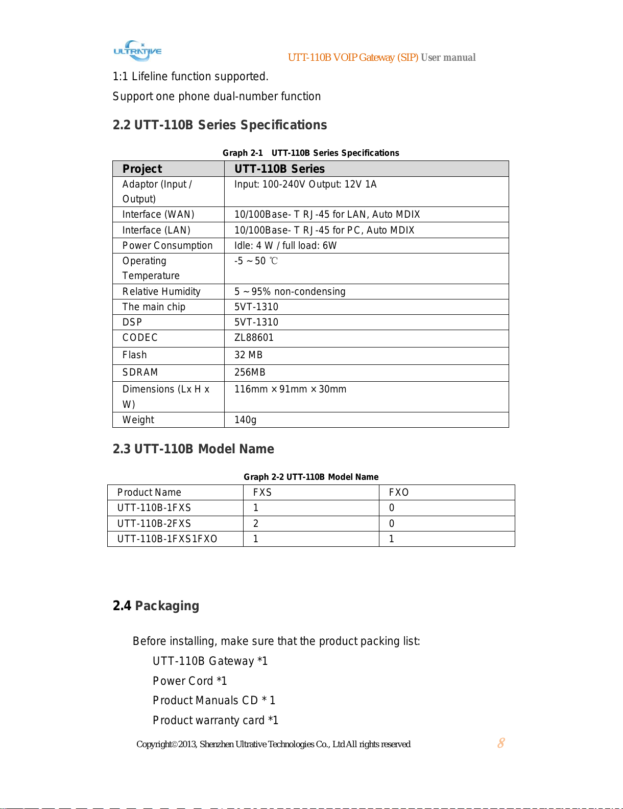
2.2 UTT-110B SERIES SPECIFICATIONS.................................................................................8
2.3 UTT-110B MODEL NAME.................................................................................................8
2.4 PACKAGING.....................................................................................................................8
2.5APPEARANCE...................................................................................................................9
2.5.1 Products Panel Diagram.........................................................................................9
2.5.2 LED Indicators ........................................................................................................9
2.6 HARDWARE CONNECTION...............................................................................................10
2.6.1 Connection to LAN by Static IP or DHCP..............................................................10
2.6.2 As a proxy server is responsible for dial-up Internet .............................................10
2.7 NETWORK ACCESS CONFIGURATION...............................................................................11
2.8 LOG-IN TO THE WEB CONFIGURATION INTERFACE ...........................................................11
PART III BASIC WEB SETTINGS.................................................................................. 14
3.1 SYSTEM MANAGEMENT..................................................................................................14
3.2 NETWORK CONFIGURATION............................................................................................16
3.2.1 WAN Settings........................................................................................................16
3.2.2 LAN Setting...........................................................................................................18
3.2.3 Route Setting........................................................................................................19
3.3 SIPSETTINGS ...............................................................................................................20
3.4 CALLPATH ...................................................................................................................22
3.4.1 Add a call path ......................................................................................................22
3.4.2 Add a call Rule......................................................................................................23
3.5 PORT SETTINGS ............................................................................................................24
3.5.1 Port Basic Settings................................................................................................25
3.5.2 Advance Settings ..................................................................................................26
3.6 PHONE NUMBER SETTING................................................................................................28
3.6.1 Single port phone number setting.........................................................................28
3.6.2 Port bulk configuration ..........................................................................................29
3.7 SYSTEM TOOL................................................................................................................29
3.8 PROGRESS TONE CONFIGURATION ..................................................................................30
3.9 SYSTEM STATUS ............................................................................................................31
All manuals and user guides at all-guides.com

UTT-110B VOIP Gateway (SIP) User manual
Copyright©2013, Shenzhen Ultrative Technologies Co., Ltd All rights reserved
4
PART 4 IVR INQUIRY AND IP ADDRESS CONFIGURATION.................................... 32
4.1 WAN PORT IPINQUIRYAND CONFIGURATION ...................................................................32
4.2 LAN PORT IPINQUIRYAND CONFIGURATION ....................................................................33
4.3 INQUIRY PHONE NUMBER OF THE PORT............................................................................33
PART FIVE TYPICAL APPLICATION CONFIGURATION(16FXS+16FXO)................... 33
5.1 CONFIGURATION OF FXS+FXO PORT EQUIPMENT FOR DIAL “9” IN SECONDARY DIAL ..........33
5.2 FXS+FXO EQUIPMENT FXO PORT CONFIGURATION—CORRESPONDING FXS PORT .......38
All manuals and user guides at all-guides.com

UTT-110B VOIP Gateway (SIP) User manual
Copyright©2013, Shenzhen Ultrative Technologies Co., Ltd All rights reserved
5
Part I Manual Guidance
1.1 Purpose
In order to help users of our devices to understand and use our UTT-110B Series
GWs more effectively, hereby, we present this User Manual with our sincerity. This Manual
consists of all detailed information that one need to know about the products.
1.2 Target Readers
The target readers of this manual includes:
I.T. Engineer
Sales Engineer
NOC
1.3 About the content
UTT-110BSeries VOIP Gateway (SIP) User manual offers detailed hardware
specifications, installations, allocation and LED indication, together with elaborate WEB
configuration demonstration.
This manual has the following:
Part I: Manual Guidance
Part II: Product Introduction
Part III: Basic WEB Settings
Part IV: IVR Inquiry, IP address setting.
Part V: Typical Scenario
1.4 Remarks
All the following Examples are based on UTT-7500-16FXS16FXO as the only subject.
All manuals and user guides at all-guides.com

UTT-110B VOIP Gateway (SIP) User manual
Copyright©2013, Shenzhen Ultrative Technologies Co., Ltd All rights reserved
6
Part II Product Introduction
UTT-110B Series VOIP Gateway gives way to standard IP Audio/Fax/Data services,
which is also called Integrated Access Device or Access Gateway. Normally, in a NGN,
UTT-110B belongs to the Access Layer of the network. Its main role is to combine all
network terminals into a unified web, in order to make all services possible in the network.
By adhering all traditional circuit exchange features, UTT-110B further delivers
advantages that IP technology can bring, making smooth migration from traditional PSTN
to NGN possible; At the meantime, UTT-110B can deliver value-add services just within
the traditional PSTN network, providing a more flexible and balanced choice for
customers. This series—UTT-110B VoIP Gateways, supports 1-2 channels of VoIP
communications, has been widely used in Government Agencies, Commercial
Organizations and Large Corporate for their own communication network. It is an ideal
product to be used in where VoIP communication is required.
2.1 Characteristics of UTT-110B Series VOIP Gateway
Carrier-class reliability
Support Efforts to improve fault detection, network alarm functions.
Low Power Consumption and High Density integration.
Supports 3rd Level lightning protection
POTS Interfaces support over-current protection.
Using ripple smaller, higher-quality communication power, support surges,
power lines and other protective lap, output stability, high reliability, and
supports instantaneous power protection.
Using electromagnetic radiation shielding properties of the chassis,
electromagnetic compatibility, ROHS and so do the professional design, can
effectively shield electromagnetic interference variety of environments.
Transmission loss, loss frequency, nonlinear distortion, crosstalk attenuation,
noise, and non-cross-cross heavy heavy noise and other indicators have
reached the telecommunicationsstandard.
Flexible, powerful security policy
Support administrator login and password protection, built-in firewall function,
can effectively prevent the various network virus attacks, and improve data
security.
Multiple protocol support capabilities
Support the SIP protocol.
All manuals and user guides at all-guides.com
all-guides.com

UTT-110B VOIP Gateway (SIP) User manual
Copyright©2013, Shenzhen Ultrative Technologies Co., Ltd All rights reserved
7
Support SNMP network management protocol, centralized network
management devices, remote monitoring and maintenance.
Support T.30, T.38 voice pass-through protocol, fax service on IP bearer
network.
Support RTP / RTCP protocol, to achieve real-time voice packet encapsulation
and voice playback.
Audio Services support capabilities
Support for voice, fax, Modem services.
Support a variety of basic voice services and value-added services.
IP telephony and traditional PSTN phone switch.
Flexible access
Support IP line access.
Support xDSL dial-up access.
Support Cable Modem access.
Diversity management
Support for SNMP-based remote centralized network management device.
Web-based network management support equipment.
Powerful QoS guarantee
Based on IPv4 Tos and DiffServ support services to ensure the voice priority.
Support IEEE802.1P, IEEE802.1Q.
Multi-adjustable parameters
Including the supply voltage can be adjusted, the loop current, ringing voltage,
long-term, short-term, impedance parameters and so on.
Advanced voice processing technology
Support ITU-T G.711a/mu, G.729, G.723.1, and other speech coding.
Support voice activity detection (VAD), effectively save network bandwidth
resources.
Support Comfort Noise Generation (CNG).
Support echo cancellation, up to 64ms.
Supports adaptive dynamic buffering technique.
Supports packet loss compensation.
Support DTMF generation / detection.
Support Caller ID detection and display functions.
Support DTMF band, SIPINFO, RFC2833 transmission technology.
Support flexible input / output gain control.
All manuals and user guides at all-guides.com

UTT-110B VOIP Gateway (SIP) User manual
Copyright©2013, Shenzhen Ultrative Technologies Co., Ltd All rights reserved
8
1:1 Lifeline function supported.
Support one phone dual-number function
2.2 UTT-110B Series Specifications
Graph 2-1 UTT-110B Series Specifications
Project UTT-110B Series
Adaptor (Input /
Output) Input: 100-240V Output: 12V 1A
Interface (WAN) 10/100Base- T RJ-45 for LAN, Auto MDIX
Interface (LAN) 10/100Base- T RJ-45 for PC, Auto MDIX
Power Consumption Idle: 4 W / full load: 6W
Operating
Temperature -5 ~ 50 ℃
Relative Humidity 5 ~ 95% non-condensing
The main chip 5VT-1310
DSP 5VT-1310
CODEC ZL88601
Flash 32 MB
SDRAM 256MB
Dimensions (Lx H x
W) 116mm × 91mm × 30mm
Weight 140g
2.3 UTT-110B Model Name
Graph 2-2 UTT-110B Model Name
Product Name FXS FXO
UTT-110B-1FXS 1 0
UTT-110B-2FXS 2 0
UTT-110B-1FXS1FXO 1 1
2.4 Packaging
Before installing, make sure that the product packing list:
UTT-110B Gateway *1
Power Cord *1
Product Manuals CD * 1
Product warranty card *1
All manuals and user guides at all-guides.com

UTT-110B VOIP Gateway (SIP) User manual
Copyright©2013, Shenzhen Ultrative Technologies Co., Ltd All rights reserved
9
Network cable *1
Telephone lines * 1-2
2.5 Appearance
2.5.1 Products Panel Diagram
Image 2-1 Front Panel
Image 2-2 Rear Panel
2.5.2 LED Indicators
Table 2-2 Front panel connectors and LEDs
Front panel
connectors
and LEDs Description
Alarm Alarm LED, all the ports open registration, while not registered
as a flashing softswitch, softswitch registration Alarm goes off.
Active Status indicators, the normal operation of the lamp is flashing.
Power Power indicator, turn the lights connected to the
power supply for the long bright state.
1-2 Port work light, off-hook, ringing, the lights are flashing during
a call, the standby is off.
Table 2-3 Rear panel connectors and LEDs
The rear panel
connectors and
LEDs Description
ON / OFF Power switch, ON / Off
AC 100-240V Power cord interface, connect the power cord.
WAN
Equipment upstream interface, when in the 10M Ethernet port
rate, the green light, orange light off; When working in the 100M
Ethernet port speed, green and orange lights are on, when the flow
of data out of date, the green light, orange lights flashing.
LAN Device configuration interface, when in the 10M Ethernet port
rate, the green light, orange light off; When working in the 100M
Ethernet port speed, green and orange lights are on, when the flow
All manuals and user guides at all-guides.com

UTT-110B VOIP Gateway (SIP) User manual
Copyright©2013, Shenzhen Ultrative Technologies Co., Ltd All rights reserved
10
of data out of date, the green light, orange lights flashing.
1FXS connected to a telephone or PBX trunk interfaces
2FXO interfaces connected to the PSTN or PBX extension
2.6 Hardware Connection
2.6.1 Connection to LAN by Static IP or DHCP
1) applies has internal LAN or home users.
2) WAN port UTT-110B Series integrated access devices connected to the hub or switch,
as shown in Figure 2-3.
3) WAN port based on the local area network environment, using PPPoE dial-up mode,
dynamically obtain IP (DHCP) or static IP mode.
Figure 2-3 Series integrated access devices in the LAN connection
2.6.2 As a proxy server is responsible for dial-up Internet
1) UTT-110B Series Voice over IP Integrated Access Device Modem WAN port directly
connected with ADSL (Cable), as shown in Figure 2-4.
2) UTT-110B Series Voice over IP Integrated Access Device as a proxy server, agent in
charge of the Internet.
All manuals and user guides at all-guides.com

UTT-110B VOIP Gateway (SIP) User manual
Copyright©2013, Shenzhen Ultrative Technologies Co., Ltd All rights reserved
11
Figure 2-4 UTT-110B Series Integrated Access Device as a proxy server connection
2.7 Network Access Configuration
Firstly confirm the connection: WAN port UTT-110B Series integrated access devices
support PPPoE, dynamic IP address or a static IP address mode
2.8 Log-in to the WEB Configuration Interface
1) selection has a computer card and TCP / IP protocol installed, the
computer and UTT-110B Series Voice over IP integrated access device's LAN
port to connect to a hub or switch with a network cable, network cable can also
be used to connect directly to the computer and the LAN port.
2) Turn on the computer "My Network Places" and "local connection", right
click and choose Properties. Below, the IP address of the computer with
UTT-110B Series Voice over IP integrated access device's LAN port IP
address is configured on the same network segment. (UTT-110B Series The
factory default LAN port IP voice integrated access device is IP
is192.168.11.1, subnet mask is 255.255.255.0.)
All manuals and user guides at all-guides.com
all-guides.com

UTT-110B VOIP Gateway (SIP) User manual
Copyright©2013, Shenzhen Ultrative Technologies Co., Ltd All rights reserved
12
Figure2-5 PC Ipaddress Setting
Ping command to test whether and UTT-110B Series IP voice
integrated access devices connected properly.
C: \> ping 192.168.11.1
Pinging 192.168.11.1 with 32 bytes of data:
Reply from 192.168.11.1: bytes = 32 time <1ms TTL = 255
If the above prompt appears, indicating that the computer has access to
the normal communication can be integrated Voice over IP devices and
UTT-110B the series.
C: \> ping 192.168.11.1
Pinging 192.168.11.1 with 32 bytes of data:
Request timed out.
Request timed out.
If the above message appears, it means that the computer and the UTT
Series Voice over IP integrated access devices connected nowhere please
first check your UTT-110B Series Voice over IP integrated access device is
connected properly (under normal circumstances, AN port status LEDs are
point bright), and then enter the "Internet Protocol (TCP / IP) Properties" page
to see if your computer's IP address is configured correctly.
3)Click ,input at the address bar http://192.168.11.1 (LAN Default IP:
192.168.11.1), then:
All manuals and user guides at all-guides.com

UTT-110B VOIP Gateway (SIP) User manual
Copyright©2013, Shenzhen Ultrative Technologies Co., Ltd All rights reserved
13
Figure2-6 WEB Login Interface
User Name:admin,Password: admin,(Default Username: admin passowrd:
admin),Click Enter then,
Figure 2-4 WEB Setting interface
All manuals and user guides at all-guides.com

UTT-110B VOIP Gateway (SIP) User manual
Copyright©2013, Shenzhen Ultrative Technologies Co., Ltd All rights reserved
14
Part III Basic WEB Settings
3.1 System Management
Login Succeeded, then go to System Management
Figure3-1 System Management Interface
Graph 3-1 System Management
System Management
Configuration Item Descriptions
System upstream
agreement Default device using SIP protocol dropdown MGCP/H248
temporarily not take effect.
RFC2833 payload
type With DTMF mode "rfc2833" use. Default value 101, a
limited range of values from 97 to 101. Default, the
parameters to be consistent with the peer device, but it can
also auto-negotiation.
RTP start port Min sending and receiving RTP port, this parameter
can not be less than 3000, it is recommended to configure
the default value can not be less than 10,000, and can be
modified.
RTP port step RTP step parameter settings, the default port 10, the
drop-down can be modified.
WEB port Log WEB configuration interface of the
portfacilities, with a default value of 80, can be modified.
Telnet port telnet port used to configure the device, the default
All manuals and user guides at all-guides.com

UTT-110B VOIP Gateway (SIP) User manual
Copyright©2013, Shenzhen Ultrative Technologies Co., Ltd All rights reserved
15
23, can be modified.
Hook without dialing
timeout The default value is 16s, the drop-down can be
modified.
Between dialing
timeout The default value 4s, drop-down can be modified.
Ringing Timeout Telephone ringing timeout, the default 60s, the
drop-down can be modified.
Ringback Timeout Hear the ringback tone timeout, the default 60s, the
drop-down can be modified.
Busy Timeout Hear a busy tone timeout, the default 120s, drop-down
can be modified.
Howler tone timeout Hear the sound of howler timeout defaults 300s,
drop-down can be modified.
Extension number
format Line with the distinction between inside and
outside the ring to use Caller ID defaults 6xxx format for
extension number, use the intercom ringing pattern.
Inside the ring pattern Mode 1:1 S pass 4S off; Mode 2:2 S pass 4S off;
model 3:0.5 S pass through 0.5S 5S 4S broken
off; Mode 4:1 S can be modified throughthe
drop-down 3S off.
Normal ringing mode Mode 1:1S pass 4S off; Mode 2:2S pass 4S off;
model 3:0.5S pass 0.5S off 0.5S pass 4S off;
Mode 4:1 S can be modified throughthe
drop-down 3S off.
Hold mode The default value for the signaling mode, you can select
local playback.
Administrator name Default administrator name admin, can be modified.
Administrator
Password Default admin password admin, can be modified.
SNMP master server Fill in this SNMP master server IP address or
domain name.
SNMP standby server In this alternate fill SNMP server IP address or
domain name.
Read community
name Fill in this read community name.
Write community
name Fill in this write community name.
Alarm group name Fill in this alarm group name.
Use the '#' sign as a dial
terminator After opening, '#' key to dial a terminator, after the retreat, '#'
key to send a number to call.
All manuals and user guides at all-guides.com

UTT-110B VOIP Gateway (SIP) User manual
Copyright©2013, Shenzhen Ultrative Technologies Co., Ltd All rights reserved
16
3.2 Network Configuration
3.2.1 WAN Settings
Click “Wan Settings” to modify configurations
Figure3-2 WAN Setting Interface
Table 3-2 WAN configuration
WAN configuration
items Description
Host name Names can configure the device, the device defaults to the
hostname SIP AG, the user name of the device can be configured as
required.
MAC address Display the MAC address of the WAN port.
Operating Mode WAN port mode
DHCP: Open the DHCP mode, using dynamic host configuration
protocol to obtain an IP address and other network parameters;
PPPoE: PPPoE open mode;
Static: fixed IP mode.
All manuals and user guides at all-guides.com
all-guides.com

UTT-110B VOIP Gateway (SIP) User manual
Copyright©2013, Shenzhen Ultrative Technologies Co., Ltd All rights reserved
17
Static IP address When the operating mode using When "Static", the correct
input on the configuration items available IP address, the device
defaults IP address: 192.169.0.1.
Static Mask Mask with the IP addresses, operating mode using When
"Static", you must configure the mask, the default value Mask:
255.255.255.0.
Static Gateway LAN device where the gateway IP address, operating mode
using When "Static", you must configure the gateway address, the
default value of the static gateway: 0.0.0.0.
PPPoE account When the operating mode using PPPoE mode, enter the
correct PPPoE account available, no default value.
PPPoE password When the operating mode using PPPoE mode, enter the
correct password PPPoE available, no default value.
PPPoE MTU When the operating mode using PPPoE mode, PPPoE MTU
default value 1480, the drop-down can be modified.
DNS switch DNS service is off by default, when you need to enable select
Open.
Preferred DNS
address DNS server is turned on, the preferred DNS address Default:
0.0.0.0, this can be modified in the preferred DNS server address.
Secondary DNS
address DNS server is turned on, the default secondary DNS addresses:
0.0.0.0, this can be modified alternate DNS server address.
SNTP switch SNTP service defaults to off, select open when you need to
enable.
Preferred Time
Server Preferred time server IP address Default: 207.46.197.32, this
can be modified in the preferred time server IP address.
Standby time
servers Standby time server IP address Default: 0.0.0.0, this can be
modified spare time server IP address.
Time Table Select the time zone, Default: time zone (GMT +08:00) Beijing,
pull-down can be modified.
Adaptive Switch The default value is an adaptive switch is turned on, when you
close the WAN port can be configured manually operating speed and
duplex mode.
Work rate Adaptive switch to select off, choose to work in this rate WAN
port.
Duplex mode Adaptive switch to select off, in this selection WAN port duplex
mode.
Signalling three
QOS mode The default value is disabled, choose TOS or DSCP.
Signalling three
TOS QOS signaling mode is selected as three-TOS, the TOS
three signaling default value is 0, the effective range of values 0 ~
7. IP precedence 6and 7 are used for network control
All manuals and user guides at all-guides.com

UTT-110B VOIP Gateway (SIP) User manual
Copyright©2013, Shenzhen Ultrative Technologies Co., Ltd All rights reserved
18
communications use, is not recommended to use.
Signalling three
PRECEDENCE When three QOS signaling mode is selected
as TOS,signaling three PRECEDENC default value of 0, the
effective range of values 0 ~ 7. IP precedence 6and 7for network
control communications use is not recommended to use.
Signalling three
DSCP When the signaling mode is selected as three
QOSDSCP, signaling three DSCP default value is 0.
Media three QOS
mode The default value is disabled, choose TOS or DSCP.
Media three QOS Media TOS three QOS mode selection when signaling
three TOS default value is 0, the effective range of values 0 ~
7. IP precedence 6and 7for network control
communications use, is not recommended to use.
Media triple
PRECEDENCE Media QOS mode is selected as three-TOS, the signaling
three PRECEDENC default value is 0, the effective range of values 0
~ 7. IP precedence 6and 7 are used for network control
communications use, is not recommended to use.
Media three DSCP When the media three QOS mode is selected
as DSCP,signaling three DSCP default value is 0.
VLAN The default value is off, select Open when needed.
VLAN ID After VLAN open, VLAN ID default value is 0, the effective range
of 1 to 4094
VLAN Priority After VLAN open, VLAN priority default is 0.
Media VLAN The default value is off, you need need to open.
Media VLAN ID After the media VLAN enabled, the media VLAN ID default
value is 0, the effective range of 1 to 4094.
Media VLAN
Priority After the media VLAN enabled, the media VLAN priority default
is 0.
3.2.2 LAN Setting
Click “LAN Settings” to modify configurations
Figure3-3 LAN Setting
All manuals and user guides at all-guides.com

UTT-110B VOIP Gateway (SIP) User manual
Copyright©2013, Shenzhen Ultrative Technologies Co., Ltd All rights reserved
19
Table 3-3 LAN configuration
LAN
configuration
items
Description
MAC address Display the MAC address of the LAN port.
IP addresses LAN IP address of the default is: 192.168.11.1, change the IP
address in this LAN port.
Mask LAN port mask defaults: 255.255.255.0, in this modification LAN port
mask.
DHCP DHCP server defaults to off, select Open when needed.
IP pool
starting
address
After the DHCP server is turned on, connected to the LAN port to
obtain an IP network terminal starts from that address.
End IP
address pool After the DHCP server is turned on, connected to the LAN port of
the network terminal in front of the address to obtain IP.
Lease Term IP address lease duration, the default value 7200.
The default
DNS address Default DNS Address: 202.96.128.86.
The default
gateway address Default Gateway address: 192.168.11.1.
Adaptive switch The default value is an adaptive switch is turned on, turned off
manually configure the LAN port speed and duplex mode of work.
Work rate Adaptive switch to select off, choose to work in this rate LAN port.
Duplex mode Adaptive switch to select off, in this select LAN port duplex mode.
3.2.3 Route Setting
Click “Route Settings” to modify configurations
Figure3-4Route Setting Interface
All manuals and user guides at all-guides.com

UTT-110B VOIP Gateway (SIP) User manual
Copyright©2013, Shenzhen Ultrative Technologies Co., Ltd All rights reserved
20
Table 3-4 routing configuration
Routing
configuration
items
Description
NAT is enabled When closed, the device retreat route forwarding; When turned on,
the device opens the route forwarding.
DMZ When NAT function is enabled, DMZ feature defaults to off, select
Open when needed.
DMZ server
address In the NAT feature is turned on, when the DMZ function is turned
on, fill in this DMZ address.
Port Mapping In the NAT feature is turned on, turned off when the DMZ, port
mapping is enabled by default turned off, turned on, drop down to
select the mapping protocol mapping fill WAN port, LAN mapped
address, LAN port mapping these parameters.
3.3 SIP Settings
Click Sip Settings to modify in the interface below
Figure3-5 SIP Setting Interface
Table 3-5SIP configuration
SIP configuration
items Description
Server mode General: All mainstream standard SIP protocol server;
VOS Encryption: Encryption exchange for VOS made soft;
All manuals and user guides at all-guides.com
Other manuals for UTT-110B Series
1
This manual suits for next models
3
Table of contents
Other Ultrative Gateway manuals
Popular Gateway manuals by other brands

ADTRAN
ADTRAN Total Access 916 Hardware installation guide

ZyXEL Communications
ZyXEL Communications P-793H 601156 quick start guide

DIGITAL YACHT
DIGITAL YACHT NavLink quick start guide

Yeastar Technology
Yeastar Technology TG Series user manual

Arris
Arris DG9450 quick start guide

Hitron
Hitron CODA-551x user guide