TRUCK PB-XEPI User manual

FIELDBUS
TECHNOLOGY
ETHERNET-
PROFIBUS-
INTERFACE
PB-XEPI
INSTALLATION
MANUAL
F1144/ 03

Installation PB-XEPI
D301144 0509
2

D301144 0509 Installation PB-XEPI 3
About this "Installation manual" ...................................................................5
Intended use ...............................................................................................5
Explanation of the safety instructions ...........................................................5
Menu and keyboard commands ..................................................................5
For your safety ................................................................................................6
Performance and functioning .......................................................................8
PB-XEPI features .........................................................................................8
Scope of delivery .........................................................................................8
PB-XEPI Configuration requirements ...........................................................8
Ethernet network presettings ........................................................................8
Design of the device ......................................................................................9
Connections and indicating elements .........................................................10
Mounting ...................................................................................................10
Start-up guideline .........................................................................................11
Note regarding the application software ..................................................11
Assembling and disassembling the device ...............................................12
Assembling the device ...............................................................................12
Disassembling the device ..........................................................................12
Connecting the Ethernet .............................................................................12
Connecting the power supply .....................................................................13
Configuring the device in the Ethernet network .......................................14
Connection in a network with DHCP
(Dynamic Host Configuration Protocol) ......................................................14
Connection in a network with manual IP assignment .................................15
Determining the network addresses ...........................................................16
Setting the new IP and network addresses .................................................16
Checking the Ethernet connection to the device .........................................17
Connecting the PROFIBUS ..........................................................................18
Bus terminating resistors ...........................................................................19
Content

Installation PB-XEPI D301144 05094
PB-XEPI operation modes
PROFIBUS Diagnosis .................................................................................20
PROFIBUS network access ........................................................................21
Troubleshooting ...........................................................................................22
Technical data ..............................................................................................23
Content

D301144 0509 Installation PB-XEPI 5
About this "Installation manual"
Please read this manual carefully, prior to installation. It facilitates assembly and setup
of your system and provides you with important information.
Intended use
The device is designed to be used as an interface between PROFIBUS and Ethernet
networks. Any other use is deemed non-intended use.
Explanation of the safety instructions
The following symbols and signal words used are intended to draw your attention to
special situations:
Menu and keyboard commands
The following conventions apply to menu and keyboard commands:
Danger
Warning of personal injury from voltage.
Warning
Warning of damage to device.
Note
Useful tips.
Disposal
Notes on disposal.
Courier font Window names, menu items, fields and descriptions of
combo boxes, check boxes, radio buttons and icons.
<Key> Press the indicated key.
About this "Installation manual"

Installation PB-XEPI D301144 05096
For your safety
Strictly observe the following safety instructions before connecting the device:
– Carefully plan the integration of the device into an existing system and ensure a
proper function of the system after installation.
– The device may only be assembled or disassembled by qualified, trained electrical
engineering personnel.
When installing the device, observe the regulations for handling electric components
inaccordancewithVDE0100. In addition,youmust also observe the validsafety and
accident prevention regulations (UVV) when operating the device within the
jurisdiction of the Federal Republic of Germany.
– Observe the EN 61158 PROFIBUS norm.
– Always install the device on a suitable DIN-rail (mounting rail).
– Cables used for the connection must not apply any mechanical forces to the device.
– High temperature differences between the storage site and installation site can result
in condensation within the case, which may cause the device to become damaged.
In case of high temperature differences, please wait at least three hours before
operating the device.
– Lock the connected plug (PROFIBUS) using the screw connections intended for this
purpose.
Warning
Never open the case of the device or carry out any mechanical modifica-
tions on the device. Otherwise, this may lead to damages on the device as
well as to loss of warranty.
Warning
The device contains electronic components sensitive to electrostatic dis-
charges. Damages due to electrostatic discharge can lead to premature
failure of components or intermittent faults at a later stage.
Before installing the device, divert the electrostatic discharge away from
your body and the tools used.
Warning
Small objects or liquids must not enter the case of the device (e.g. through
the ventilation slots). This may damage the device.
Never cover the ventilation slots on the device.
For your safety

D301144 0509 Installation PB-XEPI 7
Disposal
The device must be disposed of separately from normal household waste
in accordance with the 2002/96/EC (WEEE) Directive.
For your safety

Installation PB-XEPI D301144 05098
Performance and functioning
The Ethernet-PROFIBUS-Interface (PB-XEPI) as a compact gateway enables an easy
connection of PROFIBUS networks to the Ethernet.
PB-XEPI features
– Supports 2 operation modes:
integrated PROFIBUS diagnosis of the entire PROFIBUS network with alert via
email and PROFIBUS network access for other applications like PROFIBUS
Scope from Trebing & Himstedt, TH OPC Server DP from Trebing & Himstedt, FDT
frame application with CommDTM PROFIBUS DP-V1 from Trebing & Himstedt or
Emerson‘s AMS®Suite
– Supports leading technologies such as FDT, EDD (Emerson‘s AMS®Suite), OPC
– Supports central field device configuration, calibration and diagnosis, e.g. via
configuration tools such as FieldCare of Endress + Hauser, FieldMate from
Yokogawa, PACTware™ or Emerson‘s AMS®Suite
– Independent of process control system or PLC manufacturers
– Supports condition monitoring
– Support smart-devices asset management
Scope of delivery
– Ethenet-PROFIBUS-Interface PB-XEPI
– Documentation
PB-XEPI Configuration requirements (not included in the scope of delivery)
– PC or notebook with Windows®2000, XP or Server 2003 (operating system
dependent on the application software used)
– Web browser (MS Internet Explorer®6 or 7) for configuration of Ethernet and
PROFIBUS diagnosis
– Application software for PROFIBUS configuration
– Enabling the ports 80 and 2364
Ethernet network presettings
– The device is preset to Ethernet network operation with a DHCP server. No Ethernet
configuration settings are required in this operating mode.
– In case of manual allocation of IP addresses the device has the following standard
IP: configuration:
IP address 169.254.0.1
Subnet mask 255.255.0.0
Standard gateway 0.0.0.0
Performance and functioning

D301144 0509 Installation PB-XEPI 9
Design of the device
(see Fig. 1)
Fig. 1: PB-XEPI (front and side view)
1 Ethernet interface 5 PROFIBUS interface
2 LED ETH 6 Terminal strip for power supply
3 LED RUN 7 Type label
4 LED PB 8 DIN-rail (not included in the scope of
delivery)
ETH
RUN
PB
PB-XEPI
ABCD
[1]
PB-XEPI
Ident No.: 6905313
HW-Release: 2.0
erial No.:
Temperature: 0...+50 °C
Current: max. 190 mA
Power upply: 19,2...28,8 VDC
ETH: Ethernet (GN/RD)
RUN: OK (GN) Error (RD)
PB: PROFIBU (GN/RD)
+
24 VDC
Made in Germany D-Mülheim/Ruhr
[2]
[3]
[5]
[7]
[4]
[6]
[8]
Design of the device

Installation PB-XEPI D301144 050910
Connections and indicating elements
[1] Ethernet interface: RJ45 (10Base-T/100Base-TX)
– LED lights yellow: Ethernet data communication
– LED lights green: physical connection available
[2] LED ETH
– ETH lights red: first start phase
– ETH flashes red: boot procedure
– ETH lights red or flashes red or green in case of an error: internal failure of the
firmware.
– ETH lights green: connection to application via Ethernet
[3] LED RUN
– RUN lights red: internal failure identified
– RUN lights green: 24 V power supply is fed
[4] LED PB
– PB lights or flashes green: device communicates via PROFIBUS
[5] PROFIBUS interface: D-Sub socket
[6] Terminal strip for +24 VDC power supply
– A: 24 V (+)
– B: 0 V (-)
– C: not assigned
– D: Earth conductor
Mounting
– 35 mm DIN rail [8] (not included in the scope of delivery)
Connections and indicating elements

D301144 0509 Installation PB-XEPI 11
Start-up guideline
The following steps are required for start-up:
1. Mount the device (see »Assembling the device« on page 12).
2. Connect to the Ethernet (see »Connecting the Ethernet« on page 12).
3. Connect to the power supply (see »Connecting the power supply« on page 13)
4. Configure the Ethernet (see »Configuring the device in the Ethernet network« on
page 14).
5. Connect the PROFIBUS (see »Connecting the PROFIBUS« on page 18).
6. If you use the PB-XEPI in the PROFIBUS network access operation mode
you have to configure PROFIBUS parameters of the device using an application
software (not included in the scope of delivery).
Note
To set the IP address manually you must connect your computer to the
device via a patch cable.
Note regarding the application software
Anapplicationsoftwarewith theappropriatedriversisrequiredfor operating
the device. The COM-DTM for usage of the PB-XEPI in FDT frame
applications is on the CD.
Start-up guideline
Installation PB-XEPI D301144 050912
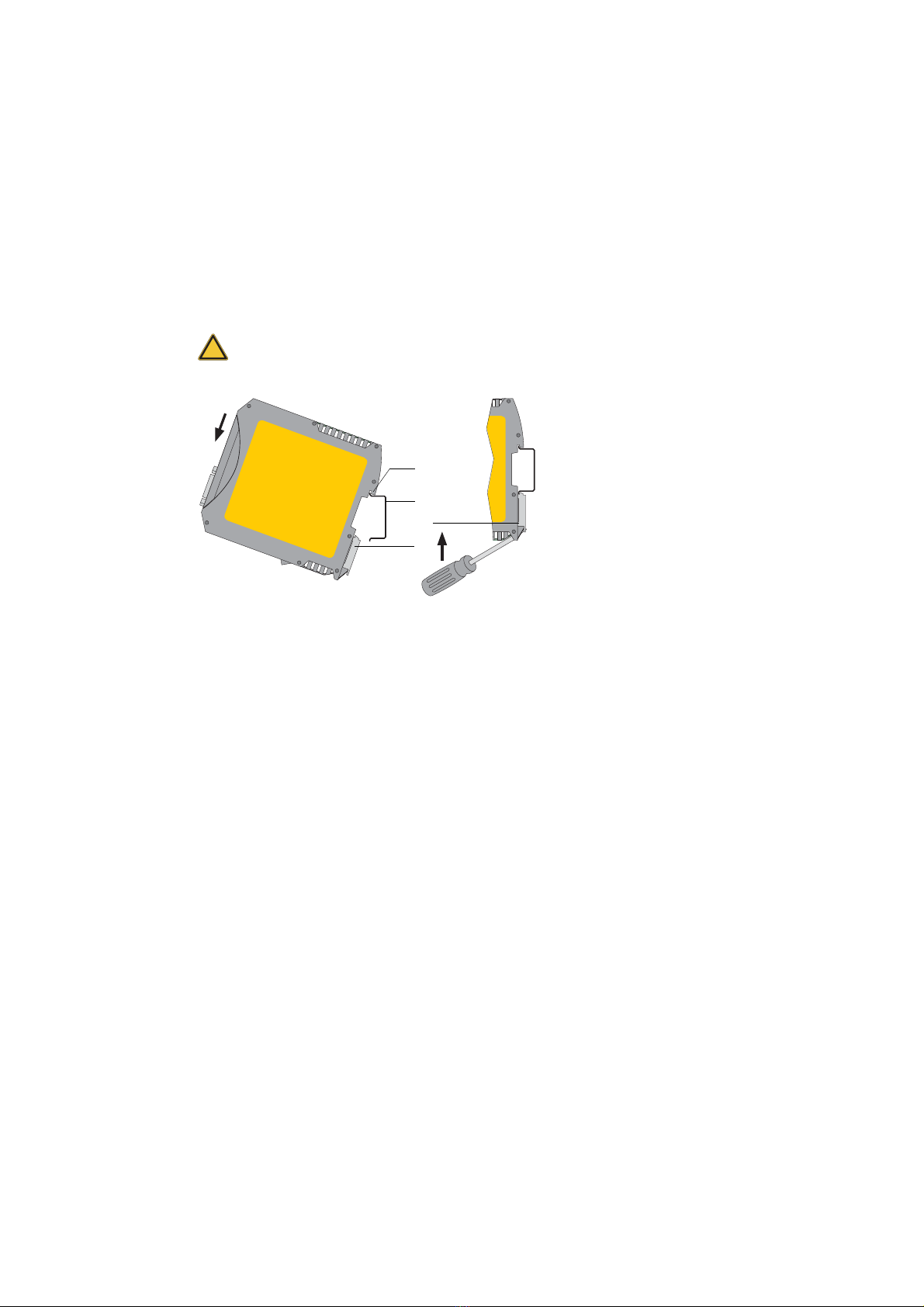
Assembling and disassembling the device
Fig. 2: Assembly and disassembly of the device
Assembling the device
1. Place the notch of the device on the DIN rail and move the device downward until
the stop lever locks into place on the DIN rail.
Disassembling the device
1. Disassemble the connected supply and signal lines (Ethernet, PROFIBUS,
voltage).
2. Place the screwdriver into the stop lever on the device (see Fig. 2, [3]).
3. Press thescrewdriver in the direction of the device and simultaneously swing the
device off the DIN rail.
Connecting the Ethernet
1. Insert the patch cable plug (RJ45, not included in the scope of delivery) into the
Ethernet socket on the device until the plug locks into place.
2. The green LED on the Ethernet socket lights as soon as the device is energized
and an Ethernet network is available.
Warning
Warning of damage to device. Above and below the device, a minimum of
5 cm head space for heat dissipation needs to be available.
1 Device with notch on DIN rail 2 DIN rail
3 Device on DIN rail 4 Stop lever
[1]
[3]
[2]
[4]
Assembling and disassembling the device

D301144 0509 Installation PB-XEPI 13
Connecting the power supply
Fig. 3: Terminal strip for power supply on the device
1. Connect the cable of a 24 V power supply and the earth conductor (earth terminal)
to the terminal strip on the device. The terminal strip can be plugged and lifted out
using a screwdriver for installation.
2. Switch on the power supply. The LED RUN flashes green until the device's
initiation procedure is completed. Afterwards the LED RUN lights green.
Danger
Electrical voltage.
Only a qualified electrician is allowed to work on the device's electrical
equipment.
Incorrect device earthing can cause injury to personnel or device damage.
Ensure correct and proper earthing of the device.
Warning
Reversepolarity in thepower supplycandamagethedevice.Make surethe
power supply is connected with correct polarity.
+24 V not assigned0 V Earth conductor
Connecting the power supply

Installation PB-XEPI D301144 050914
Configuring the device in the Ethernet network
There are two connecting options to choose from, depending on your Ethernet network:
– Ethernet network with DHCP server – automatic and dynamic allocation of IP
addresses (connection with patch cable via hub or switch)
– Ethernet network (Peer-to-Peer) – manual allocation of IP addresses (connection via
patch cable)
Connection in a network with DHCP
(Dynamic Host Configuration Protocol)
The device is preset to Ethernet network operation with a DHCP server and in this case
it is automatically assigned an IP address. This operation mode does not require con-
figuration settings.
Note
If you connect the Ethernet with the power supply already connected, the
DHCP may fail to be identified. The routine for the DHCP identification only
runs during device start-up. Briefly switch off the power supply for a new
DHCP identification.
Configuring the device in the Ethernet network

D301144 0509 Installation PB-XEPI 15
Connection in a network with manual IP assignment
If you use the device in an Ethernet network without DHCP server, you need the
following for configuration:
– TCP/IP settings for this network.
– A PC/notebook with a web browser.
– A patch cable between PC/notebook and device (peer-to-peer connection).
The device has the following manual default IP addresses (default settings at the time
of delivery):
Note
The computer must be in the same network as the device.
Note
Always notify your system administrator prior to allocating IP addresses.
If you set an address already assigned, other devices in the network may
be deactivated and communication may be affected.
IP address 169.254.0.1
Subnet Mask 255.255.0.0
Standard gateway 0.0.0.0
Connection in a network with manual IP assignment

Installation PB-XEPI D301144 050916
Determining the network addresses
Ask your system administrator for the IP addresses or do the following:
1. Connect your PC/notebook to the Ethernet network into which the device is to be
integrated.
2. Start the MS-DOS prompt.
3. Enter ipconfig -all. All settings for your network are displayed. Note down
the settings for subnet mask and standard gateway.
Setting the new IP and network addresses
1. Connect a patch cable to the device.
2. Connect a PC/notebook to the patch cable.
3. Start a Web browser on your PC/notebook (MS Internet Explorer 6 or 7).
4. Enter the IP address http://169.254.0.1 and press <Enter>. The PB-XEPI
web site loads. A pop-up window opens. Please read the information carefully and
close the window after that.
5. Then click the Settings tab. Information on the device is displayed in the web
browser.
Fig. 4: Setting the IP and network addresses
Determining the network addresses

D301144 0509 Installation PB-XEPI 17
6. Select as user Admin to login as an administrator. The default password is the six-
figure serial number of the device.
We recommend to change the password after login. Click on Change and enter
the new password. Repeat the password and click Apply.
7. Select Manual in the Network configuration.
8. Enter the new IP address into the text field.
9. Enter the new addresses for Subnet mask and Default gateway into the
text fields.
10. Note down the set IP address.
11. If you do not want to use a DNS-Server, select No, otherwise enter the IP
addresses.
Click on the diskette to save the settings. The device restarts after this.
Checking the Ethernet connection to the device
You can check the device in the Ethernet network, if:
– The device is integrated into the Ethernet network
– The device is energized
– The PC/notebook is in the same Ethernet network.
Procedure
Start a web browser on your PC/notebook (e.g. MS Internet Explorer®).
– Via DHCP: Enter the default host name (consisting of Turck_+serial number) found
on the device's type label (e.g.: Turck_000915) and press <Enter>.
– Manual IP configuration: Enter the set IP address (basic setting: 169.254.0.1)
and press <Enter>.
Information on the PROFIBUS network is displayed in the web browser.
Note
Thedevice savesyour settings. Youcanonly accesstheconfigurationpage
of the device and modify settings using these addresses.
After manual TCP/IP configuration settings, the device always starts with
the latest saved configuration - even if the power supply was switched off
for a short time.
Determining the network addresses
Installation PB-XEPI D301144 050918
Connecting the PROFIBUS
The 9-pin D-Sub socket is used for connection.
– Only use standard PROFIBUS plugs and cards.
– Wire the PROFIBUS plug according to the details for pin assignment (see Technical
data on page 23).
– If the device is installed at the beginning or end of the PROFIBUS cable segment,
you will need a bus terminating resistor (see page 19).
1. Attach the PROFIBUS connector onto the PROFIBUS socket on the device.
2. Secure the plug with screws.
3. Switchthe switch for the bus terminatingresistor on the PROFIBUS connector to the
required position (ON/OFF).
Fig. 5: Possibilities for interface connection in the PROFIBUS network
Warning!
Do not use branch lines for the connection.
If local conditions do not allow a direct connection, use a repeater (connec-
tion according to PROFIBUS norm).
1 Connection at end/start of bus with terminating resistor
2 Connection in the middle of the PROFIBUS segment 1
3 Connection in a seperate PROFIBUS segment behind a
repeater.
MasterRepeater
SlaveSlave Slave
PROFIBUS
[1] [2] [3]
Connecting the PROFIBUS

D301144 0509 Installation PB-XEPI 19
Bus terminating resistors
Terminations of a PROFIBUS network must each be terminated with a bus terminating
resistor. Use standardized plugs containing terminating resistors.
.
Fig. 6: Bus termination configuration for PROFIBUS (see PROFIBUS standard IEC
61185)
Setting PROFIBUS parameters
Depending on the application software (not included in the scope of delivery) used, the
device can be a passive station (without an own station address) or an active station
(class 2 PROFIBUS master).
The setting of the PROFIBUS parameters is only required, if you use the device as a
class 2 PROFIBUS master or in the operation mode PROFIBUS network access. The
PROFIBUS parameters are given by the class 1 PROFIBUS master.
1 390 ΩPull-up resistance from pin 3 to positive supply voltage at pin 6
2 220 ΩCable terminating resistor between pin 3 and pin 8
3 390 ΩPull-down resistance from pin 8 to data reference potential at pin 5
Warning
The PROFIBUS is shorted if you use the device as a passive terminating
resistor (supply voltage from the device) andthe deviceis switchedoff.This
may cause disruption or complete failure of PROFIBUS communication.
Use active resistors to avoid this problem. In this case the terminating re-
sistors are fed with +5 V and GND independently from the device.
+5 V DC/DC
(Pin 6)
Data+
(Pin 3) Data–
(Pin 8) GND
DC/DC
(Pin 5)
[2] [3]
[1]
Bus terminating resistors
Installation PB-XEPI D301144 050920
PB-XEPI operation modes
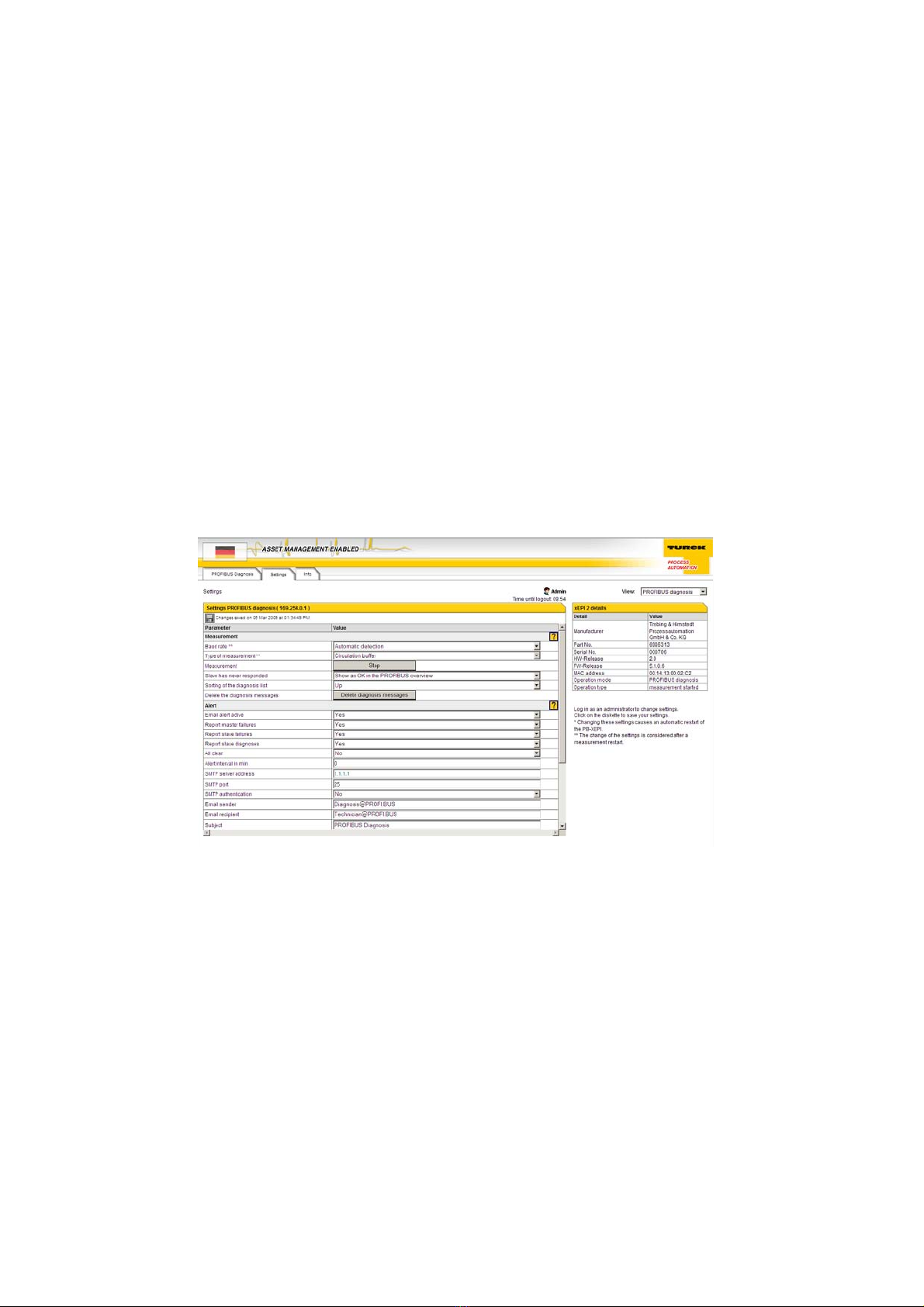
PROFIBUS Diagnosis
The default setting at delivery of the device is the PROFIBUS diagnosis mode. It ena-
bles monitoring of the entire PROFIBUS network. You can configure the monitoring set-
up.
Procede equal to „Checking the Ethernet connection to the device“ (see »Procedure«
on page 17).
Click on the Settings tab and login as an administrator. Select Admin as user and
enter the password (Default is the six-figure serial number of the device). Select
View - PROFIBUS diagnosis. Here you can configure the settings of
Measurement, Alert and Time Server.If you need help, click on the question mark.
Fig. 7: PROFIBUS diagnosis settings
PB-XEPI operation modes
This manual suits for next models
1
Table of contents
Popular Gateway manuals by other brands


Watchguard
Watchguard Firebox X5500E reference guide

NetComm Wireless
NetComm Wireless NF18ACV quick start guide

Black Box
Black Box IPBX424 installation guide

Bin Master
Bin Master BINCLOUD BCGW.02XXE Quick setup guide

2-Wire
2-Wire Gateway 100 Series Driver installation

Watchguard
Watchguard Firebox X55E-W Hardware guide


