Pfeiffer Vacuum HiPace PM 071 282-X User manual

Translation of the original instructions
Operating Instructions
EN
PT 0444 BEN/A (1308)
HiPace®
Backing pump relay box, shielded

Table of contents
2
Table of contents
1 About this manual. . . . . . . . . . . . . . . . . . . . . . . . . . . . . . . . . . . . . . . . . . . . . . . 3
1.1 Validity. . . . . . . . . . . . . . . . . . . . . . . . . . . . . . . . . . . . . . . . . . . . . . . . . . . . . 3
1.2 Conventions . . . . . . . . . . . . . . . . . . . . . . . . . . . . . . . . . . . . . . . . . . . . . . . . 3
2 Safety . . . . . . . . . . . . . . . . . . . . . . . . . . . . . . . . . . . . . . . . . . . . . . . . . . . . . . . . . 4
2.1 Safety precautions . . . . . . . . . . . . . . . . . . . . . . . . . . . . . . . . . . . . . . . . . . . 4
2.2 Proper use . . . . . . . . . . . . . . . . . . . . . . . . . . . . . . . . . . . . . . . . . . . . . . . . . 5
2.3 Improper use. . . . . . . . . . . . . . . . . . . . . . . . . . . . . . . . . . . . . . . . . . . . . . . . 5
3 Product description. . . . . . . . . . . . . . . . . . . . . . . . . . . . . . . . . . . . . . . . . . . . . . 6
3.1 Relay box, single phase, 7 A . . . . . . . . . . . . . . . . . . . . . . . . . . . . . . . . . . . 6
3.2 Relay box, single phase, 20 A . . . . . . . . . . . . . . . . . . . . . . . . . . . . . . . . . . 6
4 Electrical connection . . . . . . . . . . . . . . . . . . . . . . . . . . . . . . . . . . . . . . . . . . . . 7
5 Connection to the electronic drive unit. . . . . . . . . . . . . . . . . . . . . . . . . . . . . . 9
5.1 TC 110 . . . . . . . . . . . . . . . . . . . . . . . . . . . . . . . . . . . . . . . . . . . . . . . . . . . . 9
5.2 TC 400 / TM 700 . . . . . . . . . . . . . . . . . . . . . . . . . . . . . . . . . . . . . . . . . . . . . 9
5.3 TC 1200 . . . . . . . . . . . . . . . . . . . . . . . . . . . . . . . . . . . . . . . . . . . . . . . . . . 10
5.4 TCP 350 . . . . . . . . . . . . . . . . . . . . . . . . . . . . . . . . . . . . . . . . . . . . . . . . . . 10
6 Operation . . . . . . . . . . . . . . . . . . . . . . . . . . . . . . . . . . . . . . . . . . . . . . . . . . . . . 10
6.1 Operation mode backing pump. . . . . . . . . . . . . . . . . . . . . . . . . . . . . . . . . 10
7 Accessories . . . . . . . . . . . . . . . . . . . . . . . . . . . . . . . . . . . . . . . . . . . . . . . . . . . 11
8 Technical data . . . . . . . . . . . . . . . . . . . . . . . . . . . . . . . . . . . . . . . . . . . . . . . . . 11
8.1 Dimensions . . . . . . . . . . . . . . . . . . . . . . . . . . . . . . . . . . . . . . . . . . . . . . . . 12
Declaration of conformity. . . . . . . . . . . . . . . . . . . . . . . . . . . . . . . . . . . . . . . . 14

About this manual
3
1 About this manual
1.1 Validity
This operating manual is for customers of Pfeiffer Vacuum. It describes the functioning
of the designated product and provides the most important information for safe use of
the unit. The description follows applicable EU guidelines. All information provided in this
operating manual refers to the current state of the product's development. The documen-
tation remains valid as long as the customer does not make any changes to the product.
Up-to-date operating instructions can also be downloaded from www.pfeiffer-vacu-
um.com.
1.2 Conventions
Safety instructions The safety instructions in Pfeiffer Vacuum operating instructions are the result of risk
evaluations and hazard analyses and are oriented on international certification stan-
dards as specified by UL, CSA, ANSI Z-535, SEMI S1, ISO 3864 and DIN 4844. In this
document, the following hazard levels and information are considered:
Backing pump relay boxes Order number
Relay box, shielded, for backing pumps, 1-phase 7A for TC 110
and TCP 350, M8
PM 071 282 -X
Relay box, shielded, for backing pumps, 1-phase 20 A for TC 110
and TCP 350, M8
PM 071 283 -X
Relay box, shielded, for backing pumps, 1-phase 7 A for TC 400/
1200, TM 700 and TCP 350, M12
PM 071 284 -X
Relay box, shielded, for backing pumps, 1-phase 20 A for TC 400/
1200, TM 700 and TCP 350, M12
PM 071 285 -X
DANGER
Imminent danger
Indicates an imminent hazardous situation that will result in death or serious injury.
WARNING
Possibly imminent danger
Indicates an imminent hazardous situation that can result in death or serious injury.
CAUTION
Possibly imminent danger
Indicates an imminent hazardous situation that can result in minor or moderate injury.
NOTICE
Command or note
Command to perform an action or information about properties, the disregarding of
which may result in damage to the product.
4
Safety
Pictographs
Instructions in the
text
Work instruction: here you have to do something.
Symbols used Fore-vacuum flange
Vacuum flange
Exhaust flange
Electric connection
Abbreviations used TC: Electronic drive unit for turbopump
TM: Electronic drive unit and magnetic bearing controller for turbopump
TCP: Electronic drive unit for turbopump, external with power supply
2Safety
2.1 Safety precautions
●Observe all safety and accident prevention regulations.
●Regularly check the proper observance off all safety measures.
●Do not loosen any plug connection during operations.
●Keep leads and cables well away from hot surfaces (> 70 °C).
●The unit has been accredited with protection class IP 65. Take necessary measures
when installing into ambient conditions, which afford other protection classes.
●Always ensure a safe connection to the protective earthing conductor (PE, protection
class I).
●Before carrying out any work disconnect the unit and all associated installations safely
from the mains.
Prohibition of an action or activity in connection with a source of danger,
the disregarding of which may result in serious accidents
Warning of a displayed source of danger in connection with operation of
the unit or equipment
Command to perform an action or task associated with a source of dan-
ger, the disregarding of which may result in serious accidents
Important information about the product or this document
V
Duty to inform
Each person involved in the installation or operation of the unit must read and observe
the safety-related parts of these operating instuctions.
The operator is obligated to make operating personnel aware of dangers originating
from the unit or the entire system.

Safety
5
2.2 Proper use
●The relay box may only be used to control vacuum backing pumps on Pfeiffer Vacuum
turbopumps with related electronic drive units.
●The relay box may only be used up to the specified maximum contact load.
●Permissible electronic drive units for the connection of the relay boxes:
– integrated electronic drive unit TC 110 with connection cable
– integrated electronic drive unit TC 110 with TCS 12
– integrated electronic drive unit TC 400
– integrated electronic drive unit TC 400 with Y-Connector
– integrated electronic drive unit TM 700
– integrated electronic drive unit TM 700 with Y-Connector
– integrated electronic drive unit TC 1200
– integrated electronic drive unit TC 1200 with Y-Connector
– external electronic drive unit TCP 350 with adapter cable
●The shielded version supports the electromagnetic compatibility and reduces interac-
tion with other electric devices.
2.3 Improper use
Improper use will cause all claims for liability and warranties to be forfeited. Improper use
is defined as usage for purposes deviating from those mentioned above, especially:
●The connection of a mains power voltage not corresponding to the rating plate
●Operation with contact loads higher than the information on the rating plate
NOTICE
EC conformity
The manufacturer's declaration of conformity becomes invalid if the operator modifies
the original product or installs additional components.
Following installation into a plant and before commissioning, the operator must check
the entire system for compliance with the valid EU directives and reassess it accor-
dingly.

6
Product description
3 Product description
To correctly identify the product when communicating with Pfeiffer Vacuum, always have
the information from the rating plate available.
3.1 Relay box, single phase, 7 A
The relay box PM 071 282 -X / PM 071 284 -X with semiconductor relay is provided es-
pecially for the intermittent operation on Pfeiffer Vacuum diaphragm vacuum pumps. The
maximum relay contact load is 7 A.
3.2 Relay box, single phase, 20 A
The relay box PM 071 283 -X / PM 071 285 -X with mechanical relay is provided for the
operation of larger Pfeiffer Vacuum backing pumps. The maximum relay contact load is
20 A.
Fig. 1: View of backing pump relay box, shielded, 7 A
1 Casing / relay box
1a Control cable
6 Cable fitting M16
7 Cable fitting M12
1
7
1a6
Fig. 2: View of backing pump relay box, shielded, 20 A
1 Casing / relay box
1a Control cable
11 Cable fitting M16
12 Cable fitting M12
1
12
1a
11
11
Electrical connection
7
4 Electrical connection
Unscrew and remove the cover of the relay box.
Pay attention to grounding cables!
Install the power supply and the backing pump connection, according to their technical
data to the terminals of the relay box.
– L/L1: Conductor
– N: Neutral
– PE: Protective earth
Secure cables with cable fittings.
Close the relay box.
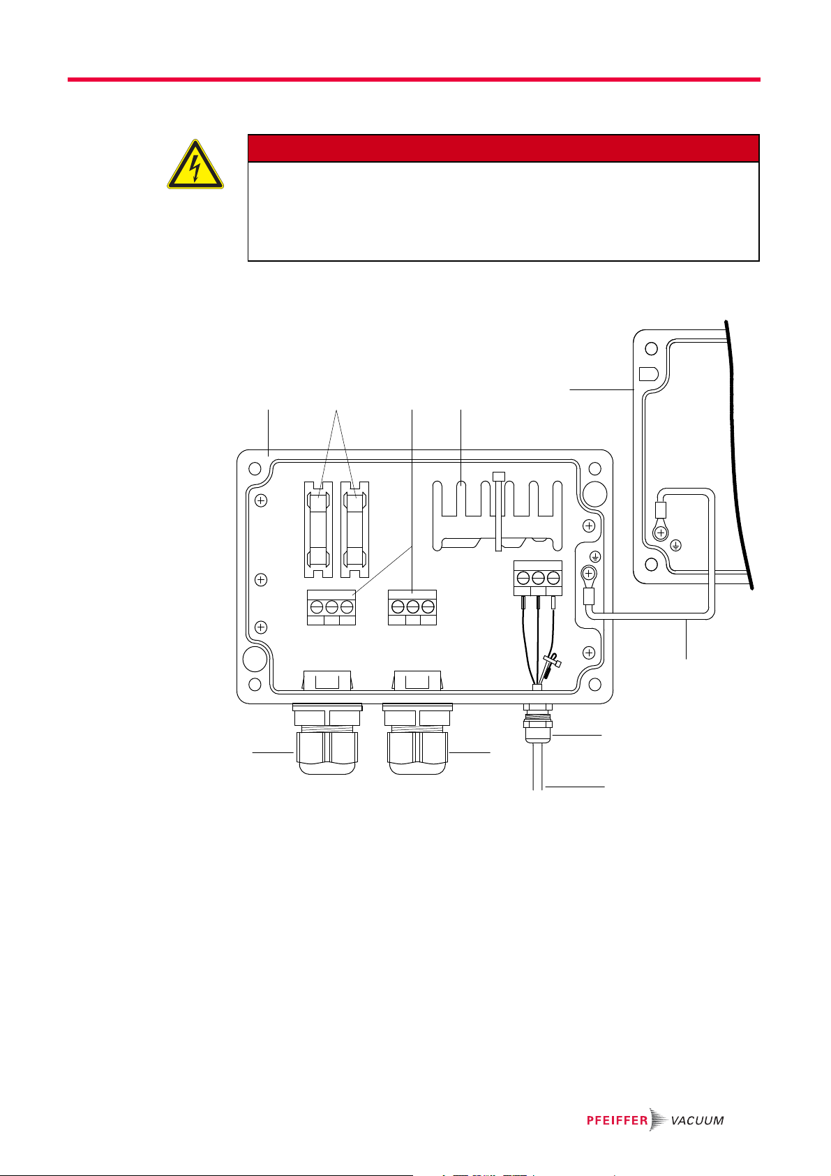
DANGER
Voltage-bearing elements
Danger to life from electric shock as a result of improper installation.
Electrical connection may be carried out only by trained and authorised electricians.
Ensure the system is adequately earthed.
Establish an adequate fuse protection on customer side (depending on the model).
Fig. 3: Backing pump relay box, single phase, 7 A
1 Casing
1.1 Casing cover
1a Control lead for electronic drive unit
1b Mains connection output, backing pump
1c Mains connection input
3 Connection terminal
4 Semiconductor relay
6 Cable fitting M16
7 Cable fitting M12
9 Fuse
11 Earthing cable
L/L1 Conductor (black)
N Neutral (blue)
PE Protective earth (yellow/green)
L N PE L1 N PE
1
1a1c1b
43
66
7
1.1
11
9
+ -
Shield
AC inAC out

8
Electrical connection
Install the power supply and the backing pump connection, according to their technical
data to the terminals of the relay box.
– L/L1: Conductor
– N: Neutral
– PE: Protective earth
Secure cables with cable fittings.
Close the relay box.
1
1a
12
1.1
11
11
+-
Shield
AC in
AC out 20
L1
N
PE
PE
N
L
3
1c
1b
Fig. 4: Relay box for backing pump, single
phase, 20 A
1 Casing
1.1 Casing cover
1a Control lead for electronic drive unit
1b Mains connection output, backing pump
1c Mains connection input
3 Relay
11 Cable fitting M16
12 Cable fitting M12
20 Earthing cable
L/L1 Conductor (black)
N Neutral (blue)
PE Protective earth (yellow/green)

Connection to the electronic drive unit
9
5 Connection to the electronic drive unit
Relay box model and connection to a Pfeiffer Vacuum turbopump depends on the re-
spective electronic drive unit and the applied backing pump.
5.1 TC 110
Connect the control lead of the relay box to the electronic drive unit via a connection
cable (e.g. PM 061 351 -T) or via TCS 12.
Make the settings and control via the interfaces of the electronic drive unit.
5.2 TC 400 / TM 700
Connect the control lead of the relay box directly to a vacant accessory port of the
electronic drive unit or using an Y-Connector.
Make the settings and control via the interfaces of the electronic drive unit.
Caption for the connection of the relay box to turbopump and backing pump
1 Backing pump relay box
1a Control lead
1b Connection backing pump
1c Mains input connection
V
1a
TC 110
PM 061 351 -T 1b
1c
1
V
1a
TC 400
1b
1c
1

10
Operation
5.3 TC 1200
Connect the control lead of the relay box directly to a vacant accessory port of the
electronic drive unit or using an Y-Connector.
Make the settings and control via the interfaces of the electronic drive unit.
5.4 TCP 350
Connect the control lead of the relay box to the "remote" connection of the electronic
drive unit using an adapter cable.
Make the settings and control via the interfaces of the electronic drive unit.
6Operation
Establish the mains supply for the relay box.
– Make sure the supply voltage for the backing pump is valid.
– Observe the rating plates!
6.1 Operation mode backing pump
Operation of a connected backing pump via the electronic drive unit depends on the
backing pump type.
Adjust the parameter [P:025] to the desired value.
V
1a
TC 1200
1b
1c
1
V
1c
PM 061 376 -T
PM 061 377 -T
TCP 350 1b
1a 1
Operation mode [P:025] recommended backing pump
"0" continous operation all kinds of backing pumps
"1" Intermittend operation diaphragm pumps only
"2" Delayed switching on all kinds of backing pumps

Accessories
11
Continous operation With "pumping station on", the electronic drive unit sends a signal to the configured ac-
cessory connection to switch on the backing pump. This signal can also be used for con-
trolling a fore-vacuum safety valve.
Intermittend opera-
tion (diaphragm
pumps only)
Intermittend operation can extend the life expectancy of the membrane of a connected
diaphragm pump. Either a diaphragm pump with built-in semiconductor relay or an inter-
connected relay box with semiconductor relay is required for intermittend operation. The
backing pump is switched on and off in dependence of the turbopump's power consump-
tion. A relation to the supplied fore-vacuum pressure is derived from the power consump-
tion. The switching off and switching on thresholds for the backing pump are adjustable.
Fluctuations in the power consumption of idling turbopumps and type-dependent varying
fore-vacuum pressures of the backing pumps require the switching thresholds to be set
separately for the intermittend mode.
Pfeiffer Vacuum recommends the intermittend mode between 5 and 10 hPa. A pressure
gauge and a dosing valve are required to set the switching thresholds.
Switch on the vacuum system via the function "pumping station" and await the run-up.
Generate a fore-vacuum pressure of 10 hPa by gas inlet via dosing valve.
Read and note the parameter [P:316].
Adjust the switch on threshold backing pump via parameter [P:711] to the determined
drive power for a fore-vacuum pressure of 10 hPa.
Reduce the fore-vacuum pressure to 5 hPa.
Read and note the parameter [P:316].
Adjust the switch off threshold backing pump via parameter [P:710] to the determined
drive power for a fore-vacuum pressure of 5 hPa.
Delayed switching on Switching on the turbopump and the backing pump at the same time can result in un-
wanted gas flows. Depending on process or application requirements, the backing pump
can be switched on with a delay. The switch-on delay depends on the rotation speed of
the turbopump and is fixed in the electronic drive unit at 6 Hz.
The switch-on delay signal can also be used for switching a fore-vacuum safety valve.
7 Accessories
An overview about original Pfeiffer Vacuum accessories for the designated device can
be found in the operating instructions of the respective vacuum pump.
8 Technical data
Parameter Relay box, shielded,
for backing pumps Relay box, shielded,
for backing pumps
Mains requirement: frequency (range) 50/60 Hz 50/60 Hz
Mains requirement: voltage (range) 100-240 (± 10 %) V AC 100-240 (± 10 %) V AC
Contact rating 7 A 20 A
Control voltage 24 V DC 24 V DC
12
Technical data
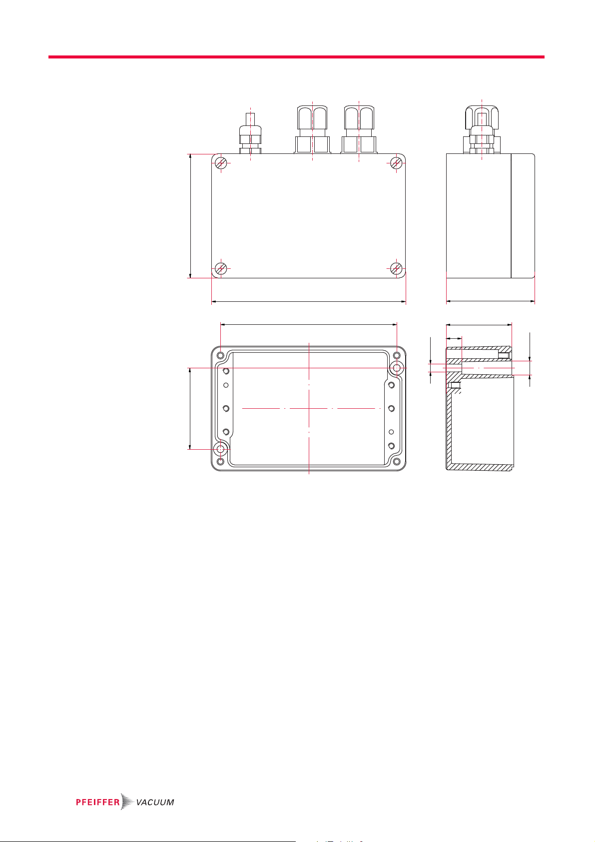
8.1 Dimensions
Fig. 5: Dimensions of the relay boxes (7 A) and pattern of fixing holes
125
113
52 80
57
42
10
Ø 4.8
Ø 9/8
Technical data
13
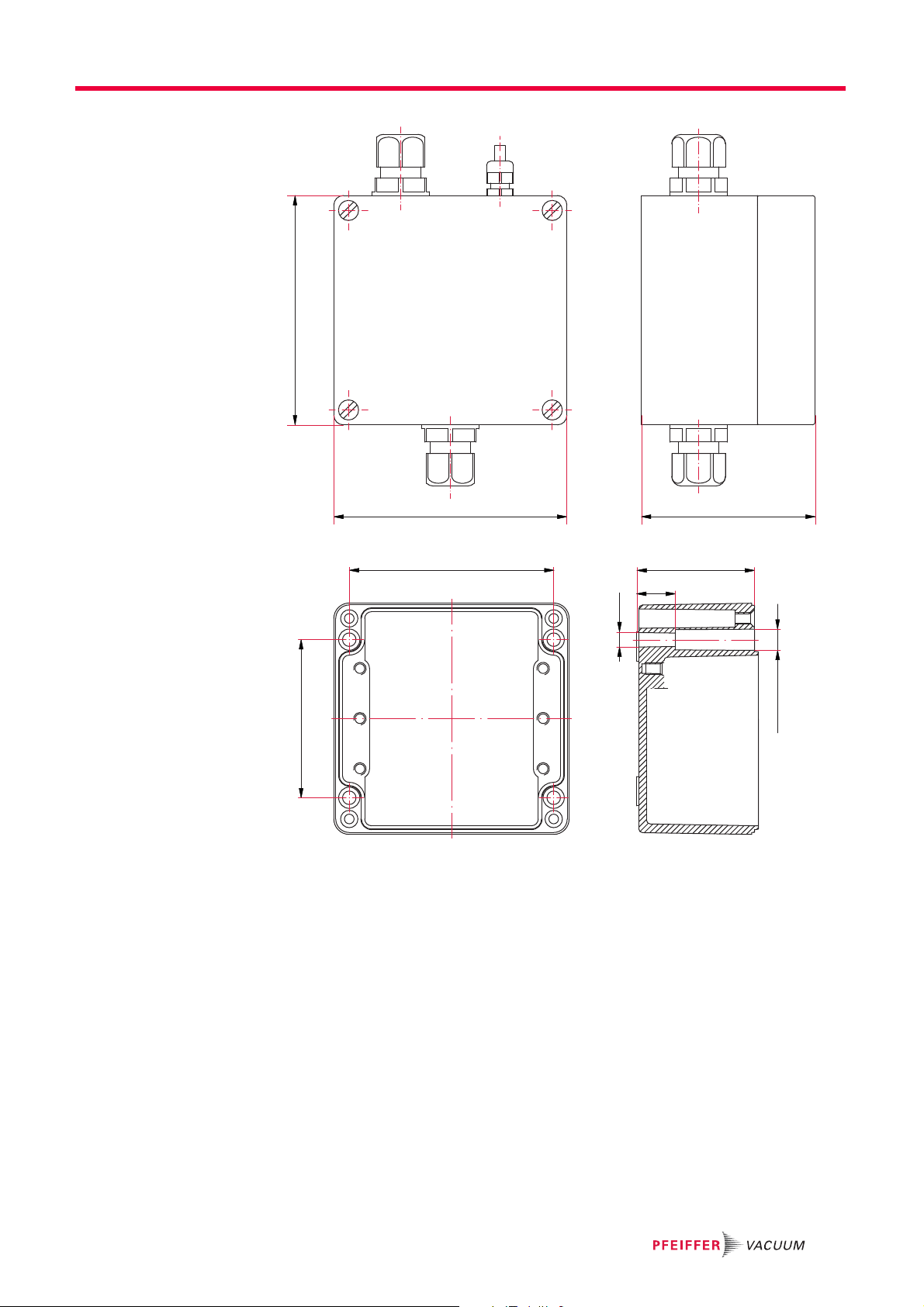
Fig. 6: Dimensions of the relay boxes (20 A) and pattern of fixing holes
120
122 91
61
20
Ø 7
Ø 11/10.5
82
106

Declaration of conformity
We hereby declare that the product cited below satisfies all relevant provisions accord-
ing to the following EC directives:
●Low Voltage 2006/95/EEC
●Electromagnetic Compatibility 2004/108/EC
PM 071 282 -X / PM 071 283 -X / PM 071 284 -X / PM 071 285 -X/
HiPace®
Harmonised standards and national standards and specifications which have been ap-
plied:
DIN EN 61000-3-2 : 2008
DIN EN 61000-3-3 : 2006
DIN EN 61010-1 : 2010
DIN EN 61326-1 : 2006
DIN EN 62061 : 2005
Signatures:
Pfeiffer Vacuum GmbH
Berliner Straße 43
35614 Asslar
Germany
(M.Bender)
Managing Director
(Dr. M. Wiemer)
Managing Director
CE/2013

Are you looking for a
perfect vacuum solution?
Please contact us
Pfeiffer Vacuum stands for innovative and custom
vacuum solutions worldwide, technological perfection,
competent advice and reliable service.
From a single component to complex systems:
We are the only supplier of vacuum technology
that provides a complete product portfolio.
Benefit from our know-how and our portfolio of training
opportunities! We can support you with your plant layout
and provide first-class on-site-service worldwide.
Vacuum solutions
from a single source
Complete range
of products
Competence in
theory and practice
Pfeiffer Vacuum GmbH
Headquarters • Germany
T +49 6441 802-0
www.pfeiffer-vacuum.com
This manual suits for next models
3
Table of contents
Other Pfeiffer Vacuum Relay manuals


