Pfeiffer Vacuum PM 041 937-T User manual

Betriebsanleitung • Operating Instructions
Relay box for backing pumps
PM 041 937-T
PM 041 938-T
PT 0030 BE/D (0604)

2
Table of contents
Table of contents
1 About this manual. . . . . . . . . . . . . . . . . . . . . . . . . . . . . . . . . . . . . . 3
1.1 Validity. . . . . . . . . . . . . . . . . . . . . . . . . . . . . . . . . . . . . . . . . . . . . . . . 3
1.2 Conventions . . . . . . . . . . . . . . . . . . . . . . . . . . . . . . . . . . . . . . . . . . . 3
2 Safety . . . . . . . . . . . . . . . . . . . . . . . . . . . . . . . . . . . . . . . . . . . . . . . . 4
2.1 Safety precautions . . . . . . . . . . . . . . . . . . . . . . . . . . . . . . . . . . . . . . 4
2.2 Proper use. . . . . . . . . . . . . . . . . . . . . . . . . . . . . . . . . . . . . . . . . . . . . 4
2.3 Improper use. . . . . . . . . . . . . . . . . . . . . . . . . . . . . . . . . . . . . . . . . . . 4
3 Product description . . . . . . . . . . . . . . . . . . . . . . . . . . . . . . . . . . . . 5
3.1 Relay box single-phase, PM 041 937 -T. . . . . . . . . . . . . . . . . . . . . . 5
3.2 Relay box single-phase, PM 041 938 -T. . . . . . . . . . . . . . . . . . . . . . 5
4 Installation . . . . . . . . . . . . . . . . . . . . . . . . . . . . . . . . . . . . . . . . . . . . 6
4.1 Internal connection . . . . . . . . . . . . . . . . . . . . . . . . . . . . . . . . . . . . . . 6
4.2 Connection diagram . . . . . . . . . . . . . . . . . . . . . . . . . . . . . . . . . . . . . 7
4.3 Connection to the electronic drive unit . . . . . . . . . . . . . . . . . . . . . . . 8
5 Accessories. . . . . . . . . . . . . . . . . . . . . . . . . . . . . . . . . . . . . . . . . . 10
6 Technical data . . . . . . . . . . . . . . . . . . . . . . . . . . . . . . . . . . . . . . . . 10
6.1 Dimension diagrams . . . . . . . . . . . . . . . . . . . . . . . . . . . . . . . . . . . . 10
Declaration of conformity. . . . . . . . . . . . . . . . . . . . . . . . . . . . . . . 11
3
About this manual
1 About this manual
1.1 Validity
This operating manual is for customers of Pfeiffer Vacuum. It describes the func-
tioning of the designated product and provides the most important information for
safe use of the unit. The description follows applicable EU guidelines. All informa-
tion provided in this operating manual refer to the current state of the product's de-
velopment. The documentation remains valid as long as the customer does not
make any changes to the product.
Up-to-date operating instructions can also be downloaded from
www.pfeiffer-vacuum.net.
1.2 Conventions
Safety instructions The safety instructions in Pfeiffer Vacuum operating manuals are the result of risk
evaluations and hazard analyses and are oriented on international certification
standards as specified by UL, CSA, ANSI Z-535, Semi-S1, ISO 3864 and DIN 4844.
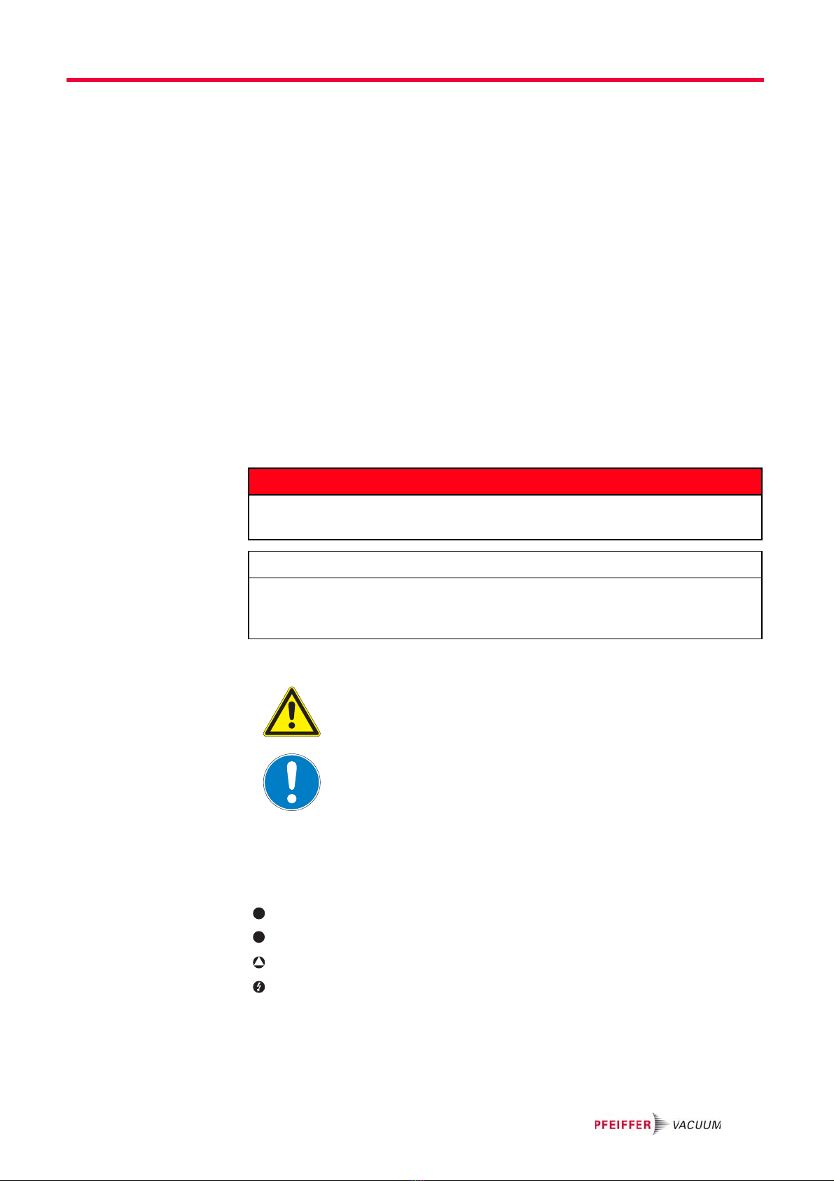
In this document, the following hazard levels and information are considered:
Piktograph
definitions
Instructions in the
text
ÎWork instruction: here you have to do something.
Symbols used Fore-vacuum flange
Vacuum flange
Exhaust flange
Electric connection
Abbreviations used TC:Electronic drive unit for turbopump
TM:Electronic drive unit for HiMag
TCP:External electronic drive unit
DANGER
Immediate danger
Death or very severe injuries occur.
NOTE
Command or note
Command to perform an action or information about properties, the disregarding of
which may result in damage to the product.
Warning of a displayed source of danger in connection
with operation of the unit or equipment.
Command to perform an action or task associated with a
source of danger, the disregarding of which may result in
serious accidents.
VV
V

4
Safety
2 Safety
2.1 Safety precautions
• Observe all safety and accident prevention regulations.
• Regularly check the proper observance off all safety measures.
• Do not loosen any plug connection during operations.
• Keep leads and cables well away from hot surfaces (> 70 °C).
• The unit has been accredited with protection class IP 65. When installing into
ambient conditions, which afford higher protection classes, the necessary
measures must be taken.
• Always ensure a safe connection to the protective earthing conductor (PE, pro-
tection class I).
• Before carrying out any work disconnect the unit and all associated installations
safely from the mains.
2.2 Proper use
• The relay box may only be used until the specified maximum contact load.
• The relay box may only be used to control vacuum backing pumps to Pfeiffer
Vacuum turbopumps with related electronic drive units.
• Permissible electronic drive units for the connection of the relay boxes are:
– integrated electronic drive unit TC 100 with TCS 010
– integrated electronic drive unit TC 600
– integrated electronic drive unit TC 750
– integrated electronic drive unit TM 3000 with connection cable PM 061 144 -X
– external electronic drive unit TCP 350 with connection cable PM 061 144 -X
2.3 Improper use
Improper use will cause all claims for liability and guarantees to be forfeited. Im-
proper use is deemed to be all use for purposes deviating from those mentioned
above, especially:
• The connection of a mains power voltage not corresponding to the rating plate
• Operation with contact loads higher than the information on the rating plate
NOTE
Duty to inform
Each person involved in the installation or operation of the unit must read and observe
the safety-related parts of these operating instuctions.
ÎThe operator is obligated to make operating personnel aware of dangers originating
from the unit or the entire system.
NOTE
CE conformity
The manufacturer's declaration becomes invalid if the operator modifies the original
product or installs additional components!
ÎFollowing installation into a plant and before commissioning, the operator must
check the entire system for compliance with the valid EU directives and reassess it
accordingly.

5
Product description
3 Product description
To correctly identify the product when communicating with Pfeiffer Vacuum, al-
ways have the information from the rating plate available.
3.1 Relay box single-phase, PM 041 937 -T
Fig. 1: Relay box PM 041 937 -T
The relay box PM 041 937 -T with semiconductor relay is provided especially for
the intermittent operation on Pfeiffer Vacuum diaphragm vacuum pumps. The
maximum relay contact load is 5 A.
3.2 Relay box single-phase, PM 041 938 -T
Fig. 2: Relay box PM 041 938 -T
20 Relay box
20a Control lead
20b Connection backing pump PG 9
20c Connection mains power input PG 11
The relay box PM 041 938 -T with mechanical relay is provided for the operation of
larger Pfeiffer Vacuum backing pumps. The maximum relay contact load is 20 A.
20 Relay box
20a Control lead
20b Connection backing pump PG 9
20c Connection mains power input PG 11
20b
20a
20
20c
20b 20a20
20c

6
Installation
4 Installation
4.1 Internal connection
ÎUnscrew and remove the cover of the relay box.
ÎInstall the wiring of the mains power and the backing pump according to the fol-
lowing illustrations.
ÎClose the relay box
Fig. 3: Relay box PM 041 937 -T, internal view
Fig. 4: Relay box PM 041 938 -T, internal view
DANGER
Voltage-bearing elements
Danger to life from electric shock.
ÎThe electrical connection can be carried out only by trained and authorised electrici-
ans.
ÎEnsure the system is adequately earthed.
20a Control lead
20b Connection backing pump
20c Connection mains power input
LPENL1PE N
20b 20c 20a
LPENL1PE N
20b
20c
20a

7
Installation
4.2 Connection diagram
Fig. 5: connection diagram PM 041 937 -T
Fig. 6: Connection diagram PM 041 938 -T
M
453621
RJ 12
Antriebselektronik /
Electronic drive unit
PE N L1
PE
F2
4 A
F1
4 A
3 x 1,5 mm2
Netzeingang /
Mains input
1
24
3
Potentialtrennung 6 mm /
Potential separation 6 mm
U1
X3.1 3 2
X1 N L
3 x 1,5 mm2
PE N L
Vorpumpe /
Backing pump
Flachleitung
4-adrig /
Flat band cable
4 core
M
PE N L1
PE
3 x 2,5 mm2
Netzeingang /
Mains input
423156
3 x 2,5 mm2
PE N L
Vorpumpe /
Backing pump
RJ 12
Antriebselektronik /
Electronic drive unit
Flachleitung 4-adrig /
Flat band cable 4 core
A1
A2
K1
N
56 7 8
9101112
K1

8
Installation
4.3 Connection to the electronic drive unit
TC 100 with TCS 010
ÎConnect the plug RJ12 of the control lead into the socket "OUT1" or "OUT2" of
the connection box TCS 010.
ÎSet up the outputs of the connection box according to the operating instructions
PM 0547 BN "Pumping operations with DCU".
ÎConnect the mains power cable of the relay box to the mains voltage.
TC 600 / TC 750
ÎConnect the plug RJ12 of the control lead into the socket "FV PUMP" on the
TC 600 or the TC 750 of the turbopump.
ÎConnect the mains power cable of the relay box to the mains voltage.
1 High vacuum flange
2 Fore-vacuum flange
8 Electronic drive unit
14 Connection box TCS 010
20 Relay box
20a Control lead
20b Connection backing pump
20c Connection mains power input
21 Vacuum backing pump
VV
1
2
14
Out1 Out2
TCS 010
TCS 010
TC 100
TC 100
8
V
21
20a
20b20c 20
100 - 240 VAC
1 High vacuum flange
2 Fore-vacuum flange
8 Electronic drive unit
20 Relay box
20a Control lead
20b Connection backing pump
20c Connection mains power input
21 Vacuum backing pump
VV
1
2
8
FV PUMP
V
21
20a
20b20c 20
100 - 240 VAC

9
Installation
TCP 350
ÎConnect the control lead of the relay box via the coupler RJ12 to the connection
cable PM 061 144 -X (accessories).
ÎPlug in the 26-pole D-Sub-plug of the connection cable into the socket "RE-
MOTE" on the TCP 350.
ÎConnect TCP and turbopump according to operating instructions PT 0092 BN.
ÎConnect the mains power cable of the relay box to the mains voltage.
TM 3000 for HiMag™
ÎConnect the control lead of the relay box via the coupler RJ12 to the connection
cable PM 061 144 -X (accessories).
ÎPlug in the 26-pole D-Sub-plug of the connection cable into the socket "REMO-
TE" on the TM 3000.
ÎConnect the mains power cable of the relay box to the mains voltage.
1 High vacuum flange
2 Fore-vacuum flange
8 Electronic drive unit
20 Relay box
20a Control lead
20b Connection backing pump
20c Connection mains power input
20d Coupler RJ 12
20e Connection cable PM 061 144 -X
21 Vacuum backing pump
VV
1
2
8
Remote
20e 20d
V
21
20a
20b20c 20
100 - 240 VAC
1 High vacuum flange
2 Fore-vacuum flange
8 Electronic drive unit and
magnetic bearing controller
20 Relay box
20a Control lead
20b Connection backing pump
20c Connection mains power input
20d Coupler RJ 12
20e Connection cable PM 061 144 -X
21 Vacuum backing pump
VV
8
1
2
Remote
20e 20d
V
21
20a
20b20c 20
100 - 240 VAC
10
Accessories
5 Accessories
6 Technical data
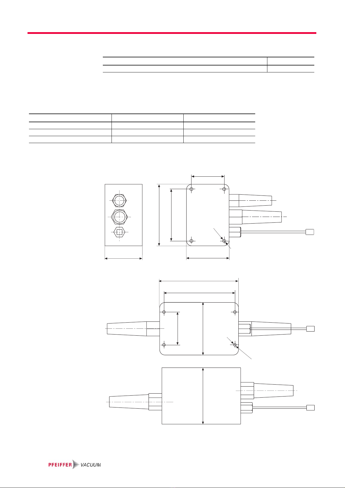
6.1 Dimension diagrams
Fig. 7: Dimensions PM 041 937 -T
Fig. 8: Dimensions PM 041 938 -T
Accessories Order number
Connection cable TCP 350 / TM 3000 - backing pump relay box, length 2 m PM 061 144-X
Values Relay box 5 A Relay box 20 A
Mains connection: voltage (range) 100-240 V AC, ±10 %, 50/60 Hz 100-240 V AC, ±10 %, 50/60 Hz
Control voltage 24 V DC 24 V DC
Contact load 5 A 20 A
50
Ø5
65
94
79
57
Steuerleitung/
Control lead
PG 9
PG 11
120
108
50
86
Ø4.5
Steuerleitung/
Control lead
PG 11
PG 11
86

Declaration of conformity
pursuant to the following EU directives:
•Electromagnetic Compatibility 89/336/EEC
•Low Voltage 2006/95/EEC
We hereby certify, that the product specified below is in accordance with the pro-
vision of EU Electromagnetic Compatibility Directive 89/336/EEC and EU Low
Voltage Directive 2006/95/EEC.
PM 041 937 -T
PM 041 938 -T
Guidelines, harmonised standards, national standards in languages and specifi-
cations which have been applied:
EN 50081-1 EN 50082-2 EN 55011 EN 60742
EN 61010 IEC 801 1-4 VDE 0843-6
Signatures:
Pfeiffer Vacuum GmbH
Berliner Straße 43
35614 Asslar
Germany
(M.Bender)
Managing Director
(Dr. M. Wiemer)
Managing Director CE/2007

Pfeiffer Vacuum Technology AG · Headquarters/Germany
Tel. +49-(0) 64 41-8 02-0 · Fax +49-(0) 64 41-8 02-2 02 · info@pfeiffer-vacuum.de · www.pfeiffer-vacuum.net
Vacuum is nothing, but everything to us!
Turbopumps
Rotary vane pumps
Roots pumps
Dry compressing pumps
Leak detectors
Valves
Components and feedthroughs
Vacuum measurement
Gas analysis
System engineering
Service
This manual suits for next models
1
Table of contents
Other Pfeiffer Vacuum Relay manuals


