Pfeiffer Vacuum MPT 100 User manual

Translation of the original instructions
Operating Instructions
EN
PG 0017 BEN/E (1112)
MPT 100
Pirani/Cold Cathode Transmitter

2
Table of contents
Table of contents
1 About this manual. . . . . . . . . . . . . . . . . . . . . . . . . . . . . . . . . . . . . . . . . . . . . . . 3
1.1 Validity. . . . . . . . . . . . . . . . . . . . . . . . . . . . . . . . . . . . . . . . . . . . . . . . . . . . . 3
1.2 Conventions . . . . . . . . . . . . . . . . . . . . . . . . . . . . . . . . . . . . . . . . . . . . . . . . 3
2 Safety . . . . . . . . . . . . . . . . . . . . . . . . . . . . . . . . . . . . . . . . . . . . . . . . . . . . . . . . . 4
2.1 Safety precautions . . . . . . . . . . . . . . . . . . . . . . . . . . . . . . . . . . . . . . . . . . . 4
2.2 Proper use . . . . . . . . . . . . . . . . . . . . . . . . . . . . . . . . . . . . . . . . . . . . . . . . . 4
2.3 Improper use. . . . . . . . . . . . . . . . . . . . . . . . . . . . . . . . . . . . . . . . . . . . . . . . 4
3 Product description. . . . . . . . . . . . . . . . . . . . . . . . . . . . . . . . . . . . . . . . . . . . . . 5
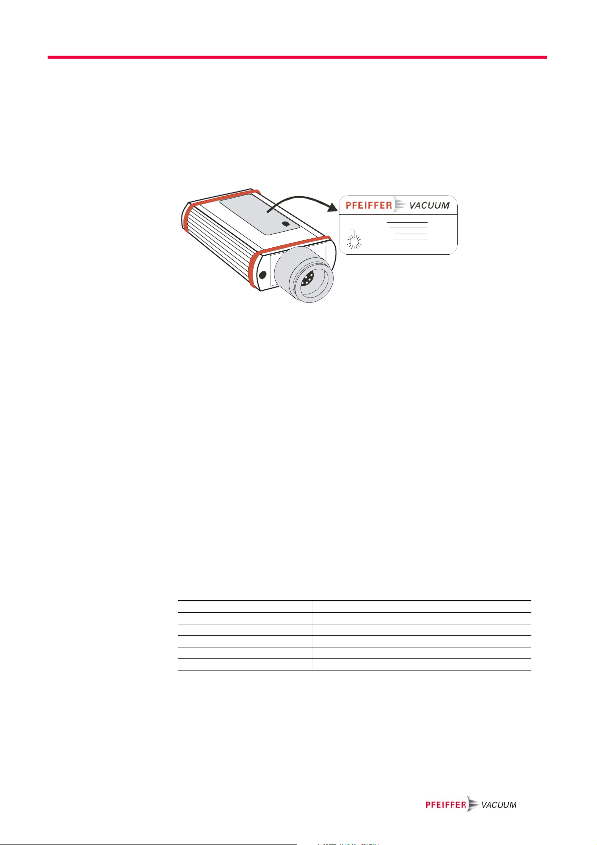
3.1 Product identification. . . . . . . . . . . . . . . . . . . . . . . . . . . . . . . . . . . . . . . . . . 5
3.2 Function . . . . . . . . . . . . . . . . . . . . . . . . . . . . . . . . . . . . . . . . . . . . . . . . . . . 5
3.3 Range of application . . . . . . . . . . . . . . . . . . . . . . . . . . . . . . . . . . . . . . . . . . 5
4 Transport and storage. . . . . . . . . . . . . . . . . . . . . . . . . . . . . . . . . . . . . . . . . . . . 6
5 Installation . . . . . . . . . . . . . . . . . . . . . . . . . . . . . . . . . . . . . . . . . . . . . . . . . . . . . 7
5.1 Vacuum connection. . . . . . . . . . . . . . . . . . . . . . . . . . . . . . . . . . . . . . . . . . . 7
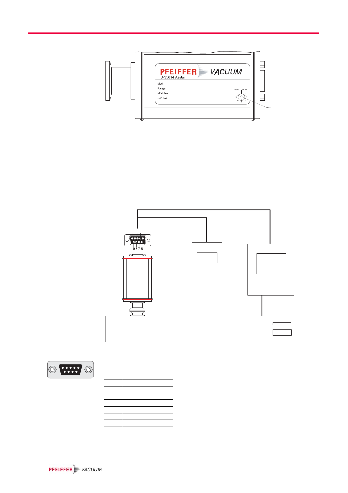
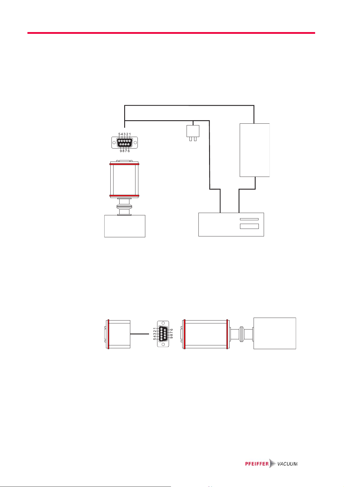
5.2 Electrical connection . . . . . . . . . . . . . . . . . . . . . . . . . . . . . . . . . . . . . . . . . . 7
5.3 Removal of components for their maintenance . . . . . . . . . . . . . . . . . . . . 10
6 Operation . . . . . . . . . . . . . . . . . . . . . . . . . . . . . . . . . . . . . . . . . . . . . . . . . . . . . .11
6.1 Before switching on. . . . . . . . . . . . . . . . . . . . . . . . . . . . . . . . . . . . . . . . . . .11
6.2 Baking out . . . . . . . . . . . . . . . . . . . . . . . . . . . . . . . . . . . . . . . . . . . . . . . . . .11
6.3 Switching on/off the CC sensor. . . . . . . . . . . . . . . . . . . . . . . . . . . . . . . . . .11
6.4 Selecting switching range . . . . . . . . . . . . . . . . . . . . . . . . . . . . . . . . . . . . . 12
6.5 Configuring the data exchange . . . . . . . . . . . . . . . . . . . . . . . . . . . . . . . . . 13
6.6 Pfeiffer Vacuum Protocol for "RS-485" . . . . . . . . . . . . . . . . . . . . . . . . . . . 15
6.7 Adjusting the transmitter . . . . . . . . . . . . . . . . . . . . . . . . . . . . . . . . . . . . . . 16
7 Malfunctions . . . . . . . . . . . . . . . . . . . . . . . . . . . . . . . . . . . . . . . . . . . . . . . . . . 17
7.1 Rectifying malfunctions . . . . . . . . . . . . . . . . . . . . . . . . . . . . . . . . . . . . . . . 17
8 Maintenance and service . . . . . . . . . . . . . . . . . . . . . . . . . . . . . . . . . . . . . . . . 18
9 Accessories . . . . . . . . . . . . . . . . . . . . . . . . . . . . . . . . . . . . . . . . . . . . . . . . . . . 19
10 Technical data and dimensions . . . . . . . . . . . . . . . . . . . . . . . . . . . . . . . . . . . 20
10.1 Technical data . . . . . . . . . . . . . . . . . . . . . . . . . . . . . . . . . . . . . . . . . . . . . . 20
10.2 Dimensions . . . . . . . . . . . . . . . . . . . . . . . . . . . . . . . . . . . . . . . . . . . . . . . . 21
10.3 Gas correction factor. . . . . . . . . . . . . . . . . . . . . . . . . . . . . . . . . . . . . . . . . 22
Declaration of conformity. . . . . . . . . . . . . . . . . . . . . . . . . . . . . . . . . . . . . . . . 23

3
About this manual
1 About this manual
1.1 Validity
This operating manual is for customers of Pfeiffer Vacuum. It describes the functioning
of the designated product and provides the most important information for safe use of
the unit. The description follows applicable EU guidelines. All information provided in this
operating manual refer to the current state of the product's development. The documen-
tation remains valid as long as the customer does not make any changes to the product.
Up-to-date operating instructions can also be downloaded from www.pfeiffer-vacu-
um.com.
1.2 Conventions
Safety instructions The safety instructions in Pfeiffer Vacuum operating manuals are the result of risk eval-
uations and hazard analyses and are oriented on international certification standards as
specified by UL, CSA, ANSI Z-535, SEMI S1, ISO 3864 and DIN 4844. In this document,
the following hazard levels and information are considered:
Pictograph
definitions
Instructions in the
text
Work instruction: here you have to do something.
Abbreviations used MPT: Digital Pirani/Cold Cathode Transmitter
CC sensor: Cold cathode sensor
NOTE
Command or note
Command to perform an action or information about properties, the disregarding of
which may result in damage to the product.
CAUTION
Possible danger
Injuries or property damages can occur.
WARNING
Possible danger
Injuries or severe property damages can occur.
Warning of a displayed source of danger in connection with
operation of the unit or equipment.
Command to perform an action or task associated with a
source of danger, the disregarding of which may result in se-
rious accidents.

4
Safety
2 Safety
2.1 Safety precautions
The transmitter MPT 100 has been tested and accepted in compliance with EN 61010/
VDE 0411 “Safety Equipment for Electrical Components”.
●Observe the safety and accident prevention regulations.
●Check regularly that all safety precautions are being complied with.
●The unit has been accredited with protection class IP 40. Take necessary measures
when installing into ambient conditions, which afford other protection classes.
●Consider possible reactions between the materials and the process media.
●Consider possible reactions of the process media due to the heat generated by the
product.
●Do not modify or alter the unit yourself.
●Note the shipping instructions, when returning the unit.
●Inform yourself about a possible contamination before starting work.
●Adhere to the relevant regulations and take the necessary precautions, when handling
contaminated parts.
●Communicate the safety instructions to other users.
2.2 Proper use
●Only use the MPT 100 digital transmitter for measuring total pressures in the
5 x 10⁻⁹ ... 1000 mbar range.
2.3 Improper use
Improper use will cause all claims for liability and warranties to be forfeited. Improper use
is deemed to be all use for purposes deviating from those mentioned above, especially:
●Connection to pumps or units which are not suitable for this purpose according to their
operating instructions.
●Connection to units which have exposed voltage-carrying parts.
●The operation of the devices in potentially radioactive areas.
NOTE
Duty to inform
Each person involved in the installation or operation of the unit must read and observe
the safety-related parts of these operating instuctions.
The operator is obligated to make operating personnel aware of dangers originating
from the unit or the entire system.

5
Product description
3 Product description
The digital transmitter MPT 100 is a two-component transmitter comprising one cold
cathode sensor and one Pirani sensor.
3.1 Product identification
To correctly identify the product when communicating with Pfeiffer Vacuum, always have
the information from the rating plate available.
Fig. 1: Product identification on the rating plate
Scope of delivery The following positions are included in the delivery consignment:
– MPT 100
– Protective cover
– Operating instructions
3.2 Function
The transmitter can be operated in conjunction with the DigiLine Controller, with the Di-
giLine Power Supply units and the WINDOWS1) based measuring software DokuStar
(please see "Accessories") on a PC or with customized, digital signal evaluation.
Communication is carried out, depending on the address selector switch setting, via the
serial RS-232 interface using the relevant display units or via RS-485 using the Pfeiffer
Vacuum protocol. The relevant bus adapters are available for connection to Profibus sys-
tems (see Accessories).
The transmitter responds to measurement value queries, type queries and setting com-
mands.
3.3 Range of application
The unit MPT 100 must be installed and operated in the following ambient conditions:
D-35641 As slar
2
4
6
8
10
12
14
RS 232 RS 4 8 5
Mod.:
Range:
Mod.-No.:
Ser.-No.:
24 V- 2,5 W
1) WINDOWS is a registered trademark of Microsoft Corporation.
Installation location weather protected (indoor)
Protection class IP 40
Installation altitude max. 2000 m
Ambient temperature +5°C to +50°C
Relative humidity 5 ... 85 %, non-condensing
Atmospheric pressure 86 kPa - 106 kPa

6
Transport and storage
4 Transport and storage
Units without external protection must not come into contact with electrostatically charge-
able materials and must not be moved within electrical or magnetic fields.
In rooms with moist or aggressive atmospheres, the unit must be airproof shrink-
wrapped in a plastic bag together with a bag of desiccant.
Keep the original protective covers.

7
Installation
5Installation
5.1 Vacuum connection
Mounting orientation The installation position can be freely selected. The preferred position is a horizontal to
vertical position so that condensate and particles do not penetrate the measurement
chamber.
Connecting the trans-
mitter
Remove the protective cover, which is required during maintenance work.
Make the flange connection.
– When making a CF flange connection, it can be advantageous to temporarily re-
move the magnet unit.
5.2 Electrical connection
Communication is effected, depending on the position of the address selector switch at
the transmitter, via Serial Interface RS-232 or via the RS-485 (address settable from 1-
15).
CAUTION
Vacuum component!
Dirt and damage impair the function of the vacuum component.
When handling vacuum components, ensure that they are kept clean and are protect-
ed against damage.
Ensure that the connection flange is clean, dry and free of grease.
CAUTION
Excess pressure in the vacuum system 1.5 to 4 bar
Damage to health through emission of process media, because elastomer washers
cannot withstand the pressure.
Use sealing rings with an outer centering ring.
CAUTION
Excess pressure in the vacuum system > 1 bar
Danger of injuries by inadvertent opening of elements under stress due to parts flying
around.
Only use stressed elements, which can be opened and closed with appropriate tools
(e.g. strap retainer-tension ring).
NOTE
Damage to the transmitter!
Only connect the connection cable when de-energized.
Never establish a connection to the transmitter using a live cable.

8
Installation
Setting the address
selection switch
Fig. 2: Setting the address selection switch
Remove the rubber plugs (not shown in the illustration) from the address selector
switch, and set the required address according to the relevant connection situation.
Connecting the trans-
mitter to the DPG 101
controller
Set the address selector switch on the transmitter to RS-232 mode (basic factory-set-
ting).
Connect the transmitter to the control unit using the connection cable.
Switch on the control unit.
Connecting the trans-
mitter to the DPG 109
controller
Up to nine transmitters in series can be conneted to the DPG 109 controller.
Fig. 3: Connections diagram transmitter-DPG
Set address selector switch S on the transmitter to RS-485 mode with the relevant ad-
dress.
Connect the transmitter to the control unit using the connection cable.
Switch on the control unit.
------------------
------------------
------------------
------------------
S
Vacuum
chamber
RS 232
DPG 101
Trans-
mitter
RS 485
DPG 109
PC
5 4 3 2 1
54
321
98
76
Pin Assignment
1 not connected
2 RS 232, RxD
3 RS 232, TxD
4 not connected
5GND
6VDC
7 RS 485: D-
8 RS 485: D+
9 not connected

9
Installation
Connecting the trans-
mitter to the DPS 101
power supply
Set the address selector switch on the transmitter to RS-232 mode (basic factory-set-
ting).
Connect the transmitter to the power supply unit and to the RS-232 interface on the
PC using the connection cable.
Plug in the power supply unit.
Operate transmitter with software DokuStar (included with DPS 101).
Connecting the trans-
mitter to the DPS 109
power supply
Fig. 4: Connections diagram - DPS 101/DPS 109
Set address selector switch S on the transmitter to RS-485 mode with the relevant ad-
dress.
Connect the transmitter to the power supply unit and to the RS-232 interface on the
PC using the connection cable.
Switch on the supply voltage with switch S1 on the power supply.
Operate the transmitter using the DokuStar Plus software (optional).
Connecting the trans-
mitter to the profibus
adapter TIC 252
Fig. 5: Connections diagram transmitter - TIC 252
Set the address selector switch on the transmitter to RS-232 mode (basic factory-set-
ting).
Plug the TIC 252 into the D-Sub socket on the transmitter and secure using fixing
screws.
Connect the power supply to the TIC 252.
RS 485
RS 232
RS 232
DPS 109
PC
DPS 101
Trans-
Vacuum
chamber
mitter
V
acuum
chamber
TIC 252 Transmitter

10
Installation
Connecting the trans-
mitter to the level
converter TIC 002
Fig. 6: Connections diagram transmitter - TIC 002
Set address selector switch S on the transmitter to RS-485 mode with the relevant ad-
dress.
Connect the transmitter to the TIC 002 using the connection cable.
Connect the power supply to the TIC 002.
Connecting the trans-
mitter to the USB/RS-
485 converter
Fig. 7: Connections diagram transmitter - USB/RS-485 converter
Set address selector switch S on the transmitter to RS-485 mode with the relevant ad-
dress.
Connect the transmitter to the USB/RS-485 converter using the connection cable.
Connect the transmitter to the power supply.
5.3 Removal of components for their maintenance
Switch off the power supply on the control unit/power supply or disconnect the equip-
ment from the mains supply.
Loosen any connection cables.
Detach the transmitter from the vacuum apparatus.
Close the flange opening by using the original protective cover.
24 V DC
TIC 002
RS-232
RS-485
PC
Transmitter
Vacuum
chamber
USB/RS485-
converter
24 V DC
Mod.:
Mod.-Nr.:
Input:
Output.
Masse:
Ser.-Nr.:42000303
RPT100
PT.........
.....V,50/60Hz ..VA
.....V,0.2 A
.....kg
D-35614Asslar
Mod.:
Mod.-Nr.:
Input:
Output.
Masse:
Ser.-Nr.:42000303
RPT100
PT.........
.....V,50/60Hz ..VA
.....V,0.2 A
.....kg
D-35614Asslar
Vacuum
chamber
Vacuum
chamber
WARNING
Contamination of transmitter parts possible due to the media measured!
Poisoning hazard through contact with harmful substances.
In the case of contamination, carry out appropriate safety precautions in order to pre-
vent danger to health through dangerous substances.
Decontaminate affected parts before carrying out maintenance work.

11
Operation
6 Operation
6.1 Before switching on
After switching on the power supply, the transmitter is ready for operation. However, it is
advisable to wait for a stabilization period of 5-10 minutes before measurement, and to
operate the transmitter without interruption during the measurement process.
The measured pressure will depend on the type of gas. A suitable gas-type correction
factor for Pirani or cold cathode components can be set in the transmitter for the pressure
range below 0.1 mbar to adjust to different gases. The gas-type correction factor is fac-
tory set for air and N2at 1.00 (see p. 22, chap. 10.3).
6.2 Baking out
Fig. 8: Disassembling sensor head and magnet unit
Loosen both set screws 1.
Pull off sensor head 2 and magnet unit 3 from the electronic 4.
Remove the magnet unit 3 from the sensor head 2.
Bake out sensor head 2.
6.3 Switching on/off the CC sensor
With this transmitter the CC sensor can be switched on/off to suit process require-
ments.This is achieved using measuring devices DPG 109 (≥V 1.40), DPG 101
(≥V 1.60), via the PC software Dokustar (≥V 2.00) or can be customized in accordance
with the communication instructions.
When the power supply is switched on, the "sensor" variable is set to "On", (default set-
ting), i.e. the MPT 100 is operating in normal mode. Status changes of this variable dur-
ing operation are stored only temporarily. The status of the "sensor" variable can be al-
tered at any time and remains stored until the power supply is switched off.
CAUTION
Excessive bake-out temperature!
Danger of damage to the electronics and the magnetic unit!
For baking out temperatures > 60°C, always remove the electronics and magnetic
unit 3 from sensor head 2 and only bake out sensor head 2.
Pay attention to the the component assignments, do not interchange.
1
2
4
3
!
!

12
Operation
Switch on/off condi-
tions
1The threshold values Pxdepend on the selected SwMode and amount 2.1 · 10-3 and respectively
1.0 · 10-3 mbar (see also “Selecting switching ranges”).
2
The Pirani pressure value is displayed until this timer expires. If "ur" is output as the Pirani value
prior to the "On" command, output 1·10
-4 mbar is set during the timer runtime (otherwise, the
"ur" display could be interpreted as CC under range during the timer runtime). Once "Switching on
Timer" has expired, the combined value from Pirani and the CC sensor is output again.
Switching on/off the CC sensor using DPG 101/DPG 109
See the Operating Instructions for the respective control unit for switching on/off the
sensor components.
Switching on/off the CC sensor for communication via RS-232- or RS-485-in-
terface
Switch on CC sensor by sending ([P:041] with value <<1>>).
Switch off CC sensor by sending ([P:041] with value <<0>>).
6.4 Selecting switching range
Depending on the application, the MPT 100 transmitter enables the adjustment of the
switching range between Pirani and cold cathode (CC) sensors to avoid
– the measuring value being used for control in the transition range or,
– in coating applications, the cold cathode being switched on and contaminated prema-
turely by the self-sputter effect.
Fig. 9: Switching ranges MPT 100
Communication with DPG
101 or DPG 109 control
unit
Select switching ranges of the sensor components according to the operating manual
for the relevant control unit.
Communication via
RS-232 or RS-485
Select switching range:
– trans_LO: Send [P:049] with value <<001>>
– switch: Send [P:049] with value <<000>>
Status of the
CC sensor Control command
with [P: 041] Pirani pressure Pp
actual1Effect on CC sensor
Switched on "On" - no effect
Switched off "On" Pxis switched on when Pp<P
x
Switched off "Off" Pxremains switched off when Pp<P
x
Switched on "Off" - is switched off
Switched off "On" Pxis switched on and the "Switching on
timer" is started.2
SwMode
trans_LO:
switch:
Overlapping at 1 ... 210-3 mbar
(CC "On" at p 2.110-3 mbar/
CC "Off" at p 3.110-3 mbar,
standard design)
Direct switching at 110-3 mbar
(CC "On" at p 110-3 mbar)
Pirani sensorKK-(CC-) sensor
1·10 ... 2·10
-3 -3
mbar

13
Operation
6.5 Configuring the data exchange
Communication is carried out, depending on the address selector switch setting, via the
serial RS-232 interface using the relevant display units or via RS-485 using the Pfeiffer
Vacuum protocol:
●9600 baud
●8 data bits
●1 stop bit
●no parity
Parameter overview
Parameters are displayed in square brackets as a three-digit number in bold font. The
designation may also be stated if necessary.
Example: [P:312] Software version
Reading the actual
pressure value
[P:740]
Pressure value as the value to be queried and also as equalization (see below) are trans-
mitted by means of a string in the format "aaaabb", whereby "aaaa" is the mantissa and
"bb" the exponent with offset 20 of an exponential number. "aaaa" is therefore in the
range "1000" (for 1.000) to "9999" (for 9.999). The individual characters of the string are
the numbers "0" (ASCII 48) to "9" (ASCII 57).
Example: "104223" represents 1.042 x 10+3 mbar, "750015" represents 7.500 x 10⁻⁵
mbar.
Reading error codes
[P:303] Parameter 303 transfers the actual error code of the transmitter. The following error
codes can occur:
Error codes
# Name Data type Handling
CPT 100
PPT 100
RPT 100
HPT 100
MPT 100
40 DeGas 6 - boolean_new readable, writable
•
41 Sensor on/off 7 - u_short_int readable, writable
•
•
49 Switch mode 7 - u_short_int readable, writable
•
•
•
303 Actual error code 4 - string read-only
•
•
•
•
•
312 Software version 4 - string read-only
•
•
•
•
•
349 Component name 4 - string read-only
•
•
•
•
•
740 Pressure in [mbar] 10 - u_expo_new readable, condition-
ally writable
•
•
•
•
•
741 Pressure set point 7 - u_short_int only writable
•
•
•
•
•
742 Correction value
(Pirani)
2 - u_real readable, writable
•
•
•
•
743 Correction value
(Bayard-Alpert)
2 - u_real readable, writable
•
743 Correction value
(CC sensor)
2 - u_real readable, writable
•
Value Meaning
"000000" No error
"Err001" Defective transmitter
"Err002" Defective memory

14
Operation
Reading component
names [P:349] Parameter 349 contains a logogram for the component name in accordance with the fol-
lowing table:
"....": means 4 blanks
Value Transmitter
".... A1" CPT 100
".... A2" RPT 100
".... A3" PPT 100
".... A4" HPT 100
".... A5" MPT 100

15
Operation
6.6 Pfeiffer Vacuum Protocol for "RS-485"
Telegram frame The telegram frame of the Pfeiffer Vacuum protocol contains only ASCII code characters
[32; 127], the exception being the end character of the message CR. Basically, a master
(e.g. a PC) sends a telegram, which is answered by a slave (e.g. electronic drive
unit or transmitter).
Telegrams Data request ?
Control command !
Data response / control command understood
Error message
Telegram examples
Read actual pressure value (data query)
(Parameter [P:740], Slave device address: "001")
Activate/send parameter for atmospheric pressure (high pressure) (control com-
mand)
Atmospheric pressure adjustment (Parameter [P:741/740], Slave device address: "001")
a2 a1 a0 * 0 n2 n1 n0 l1 l0 dn ... d0 c2 c1 c0 CR
a2 - a0 Unit address for slave
– Individual address of the unit ["001";"015"]
*Action
n2 - n0 Pfeiffer Vacuum parameter numbers
l1 - l0 Data length dn ... d0
dn - d0 Data in data type concerned
c2 - c0 Checksum (sum of ASCII values of cells a2 to d0) modulo 256
CRCarriage return (ASCII 13)
a2 a1 a0 0 0 n2 n1 n0 0 2 = ? c2 c1 c0 CR
a2 a1 a0 1 0 n2 n1 n0 l1 l0 dn ... d0 c2 c1 c0 CR
a2 a1 a0 1 0 n2 n1 n0 0 6 N O _ D E F c2 c1 c0 CR
_RANGE
_LOGI C
"NO_DEF" The parameter n2 - n0 does not exist
"_RANGE" Data dn - d0 are outside the permitted range
"_LOGIC" Logic access violation
?0010074002=?106CR
ASCII 48 48 49 48 48 55 52 48 48 50 61 63 49 48 54 13
0011074006100023025CR
ASCII 48 48 49 49 48 55 52 48 48 54 49 48 48 48 50 51 48 50 53 13
?0011074103001130CR
ASCII 48 48 49 49 48 55 52 49 48 51 48 48 49 49 51 48 13
0011074103001130CR
ASCII 48 48 49 49 48 55 52 49 48 51 48 48 49 49 51 48 13

16
Operation
Activate/send parameter for low pressure (control command)
Low pressure adjustment (Parameter [P:741/740], Slave device address: "001")
Applied data types
6.7 Adjusting the transmitter
The transmitter is factory-calibrated. It may be necessary to calibrate the Pirani sensor
in the event of contamination, other installation positions, extreme temperature fluctua-
tions, ageing, etc. This is carried out using the "DokuStar" PC software via a connected
control unit or according to customer requirements following the communication instruc-
tions.
A Pirani equalization in the "ur" range (under range) will occur automatically under the
following, simultaneously applicable conditions:
– the measuring value of the cold cathode sensor is < 5 10-5 mbar.
– the measuring value of the Pirani sensor will remain constant for 1 minute and will not
deviate too much from the last calibrated value.
Before equalization, the transmitter should be operated at the relevant pressure for ap-
prox. 5 ... 10 minutes long (warm-up time).
For correct zero point equalization, the pressure in the vacuum chamber must be below
1·10-5 mbar.
With controller
DPG 101/DPG 109:
Equalize the transmitter as described in the instructions for the control units.
Via RS-232/RS-485: Evacuate the vacuum chamber to the pressure p < 1·10-5 mbar.
Set the pressure adjusting point [P:741] to «000» for low pressure and transmit.
Send actual pressure value ([P:740] with value «000000» ) for low pressure (corre-
sponds to p < 1·10-1); ==> "ur" (under range).
Vent vacuum chamber to atmospheric pressure with air or N2; afterwards wait about
10 minutes.
Set the pressure adjusting point [P:741] to «001» for high pressure and transmit.
Set the actual pressure value to the atmospheric pressure («100023» for 1000 mbar).
?0011074103000129CR
ASCII 48 48 49 49 48 55 52 49 48 51 48 48 48 49 50 57 13
0011074103000129CR
ASCII 48 48 49 49 48 55 52 49 48 51 48 48 48 49 50 57 13
Data type Description Size l1 - l0 Example
0 False / true 06 000000 / 111111
1 Positive integer number 06 000000 to 999999
2 Positive fixed comma number 06 001571 equal to 15.71
4 Symbol chain 06 TC_400
7 Positive integer number 03 000 to 999
10 Symbol chain 06 100023

17
Malfunctions
7 Malfunctions
7.1 Rectifying malfunctions
DANGER
Strong magnetic field in the vicinity of the sensor head!
Danger of death for persons with cardiac pacemakers when the magnetic unit is disas-
sembled.
Maintenance personnel with active body aids (e.g. cardiac pacemakers) should
maintain a safe distance of at least 10 cm from the magnetic unit of the transmitter.
Disassembled magnetic unit must be kept away from computers, data storage media
and other electronic components.
Errors Possible cause: Remedy
Communication error: Transmit-
ters
●No power supply
●Incorrect interface type or incor-
rect address preset
●Transmitter faulty
Connect data cable or power-
pack.
Set address selector switch
correctly.
Change transmitter
A too large measuring value is
emitted continuously in high
vacuum.
●Strong sensor degassing
●Adjustment required
●Transmitter faulty
Clean transmitter.
Adjust transmitter.
Change transmitter.
"ur" is emitted continuously in
high vacuum, although the pres-
sure > 1 10-8
●uses starting aid Change transmitter.

18
Maintenance and service
8 Maintenance and service
The unit requires no maintenance. A damp cloth can be used to wipe away any dirt.
Do make use of our service facilities:
In the event that repairs are necessary a number of options are available to ensure any
unit down time is kept to minimum:
●Return the unit to the manufacturer for repairs;
●Replace with a new value unit.
Sending of units
Download the forms "Service Request" and "Declaration on Contamination".1)
Fill out the "Service Request" form and send it by fax or e-mail to your Pfeiffer Vacuum
service address.
Include the confirmation on the service request from Pfeiffer Vacuum with your ship-
ment.
Fill out the declaration on contamination and include it in the shipment (required!).
Seal the contaminated unit in suitable protective film.
If possible, send unit in the original packaging.
Service orders
All service orders are carried out exclusively according to our repair conditions for vacu-
um units and components.
NOTE
The unit is not prepared for customer repair.
Units returned to us for repair or maintenance are covered by our general conditions of
sale and supply.
1) Forms under www.pfeiffer-vacuum.com

19
Accessories
9 Accessories
Designation MPT 100
DPS 101, for 1 transmitter, UK plug PT G20 012
DPS 101, for 1 transmitter, US plug PT G20 011
DPS 101, for 1 transmitter, EU plug PT G20 010
DPS 109, for 9 transmitters PT G25 010
DPG 101, controller for 1 transmitter PT G10 010
DPG 109, controller for 9 transmitters PT G15 010
Connection cable for DPG 101, 3 m PT 348 203-T
Connection cable for DPG 101, 6 m PT 348 206-T
Connection cable for DPG 101, 10 m PT 348 210-T
Connection cable for DPG/DPS 109, 3 m PT 348 403-T
Connection cable for DPG/DPS 109, 6 m PT 348 406-T
Connection cable for DPG/DPS 109, 10 m PT 348 410-T
Plug-in bus termination for RS-485 PT 348 100-T
TIC 252, Profibus converter for HPT, MPT PT 348 111
USB converter to RS-485 interface PM 061 207-T
Transmitter adapter cable with RS-485 PT 348 131 -T
Connection cable TPS 110/111/180/181 - Transmitter, 3 m PT 348 142 -T

20
Technical data and dimensions
10 Technical data and dimensions
10.1 Technical data
Parameter MPT 100 MPT 100 MPT 100
Anode Mo Mo Mo
Flange (in) DN 25 ISO-KF DN 40 CF-R DN 40 CF-R
Protection category IP 40 IP 40 IP 40
Seal Metal Metal Metal
Pressure max. 4 bar 4 bar 4 bar
Feedthrough KOVAR® - Glass KOVAR® - Glass KOVAR® - Glass
Accuracy: % of mea-
surement
1 · 10-7- 1 · 10-3 mbar: ±
25, 1 · 10-2 - 100 mbar: ±
15
1 · 10-7- 1 · 10-3 mbar: ±
25, 1 · 10-2 - 100 mbar: ±
15
1 · 10-7- 1 · 10-3 mbar: ±
25, 1 · 10-2 - 100 mbar: ±
15
Weight 0.580 kg 0.580 kg 0.580 kg
Materials in contact with
media
Tungsten, stainless steel,
nickel
Tungsten, stainless steel,
nickel
Tungsten, stainless steel,
nickel
Measurement range
max.
1000 mbar 1000 mbar 1000 mbar
Measurement range
min.
5 · 10-9 mbar 5 · 10-9 mbar 5 · 10-9 mbar
Sensor cable length
max.
1000 m 1000 m 1000 m
Method of measure-
ment
Pirani/Cold cathode Pirani/Cold cathode Pirani/Cold cathode
Measuring cycle 40 ms 40 ms 40 ms
Interface: Connection Digital RS-232 / RS-485,
9-pin, D-sub-socket
Digital RS-232 / RS-485,
9-pin, D-sub-socket
Digital RS-232 / RS-485,
9-pin, D-sub-socket
Cold cathode sensor
control
Cold cathode sensor can
be switched on and off
via interface
Cold cathode sensor can
be switched on and off via
interface
Cold cathode sensor can
be switched on and off via
interface
Temperature: Bakeout
(electronics removed)
180 °C 180 °C 180 °C
Temperature: Operating 5-50 °C 5-50 °C 5-50 °C
Temperature: Storage -40-+60 °C -40-+60 °C -40-+60 °C
Supply: Voltage 24 V DC 24 V DC 24 V DC
Supply: Power con-
sumption max.
2.5 W 2.5 W 2.5 W
Volume 9.5 cm³ 9.5 cm³ 9.5 cm³
Repeatability: % of
measurement
1 · 10-7 - 100 mbar: ± 5 1 · 10-7 - 100 mbar: ± 5 1 · 10-7 - 100 mbar: ± 5
Ignition aid Stainless steel Stainless steel Stainless steel
Table of contents
Other Pfeiffer Vacuum Transmitter manuals