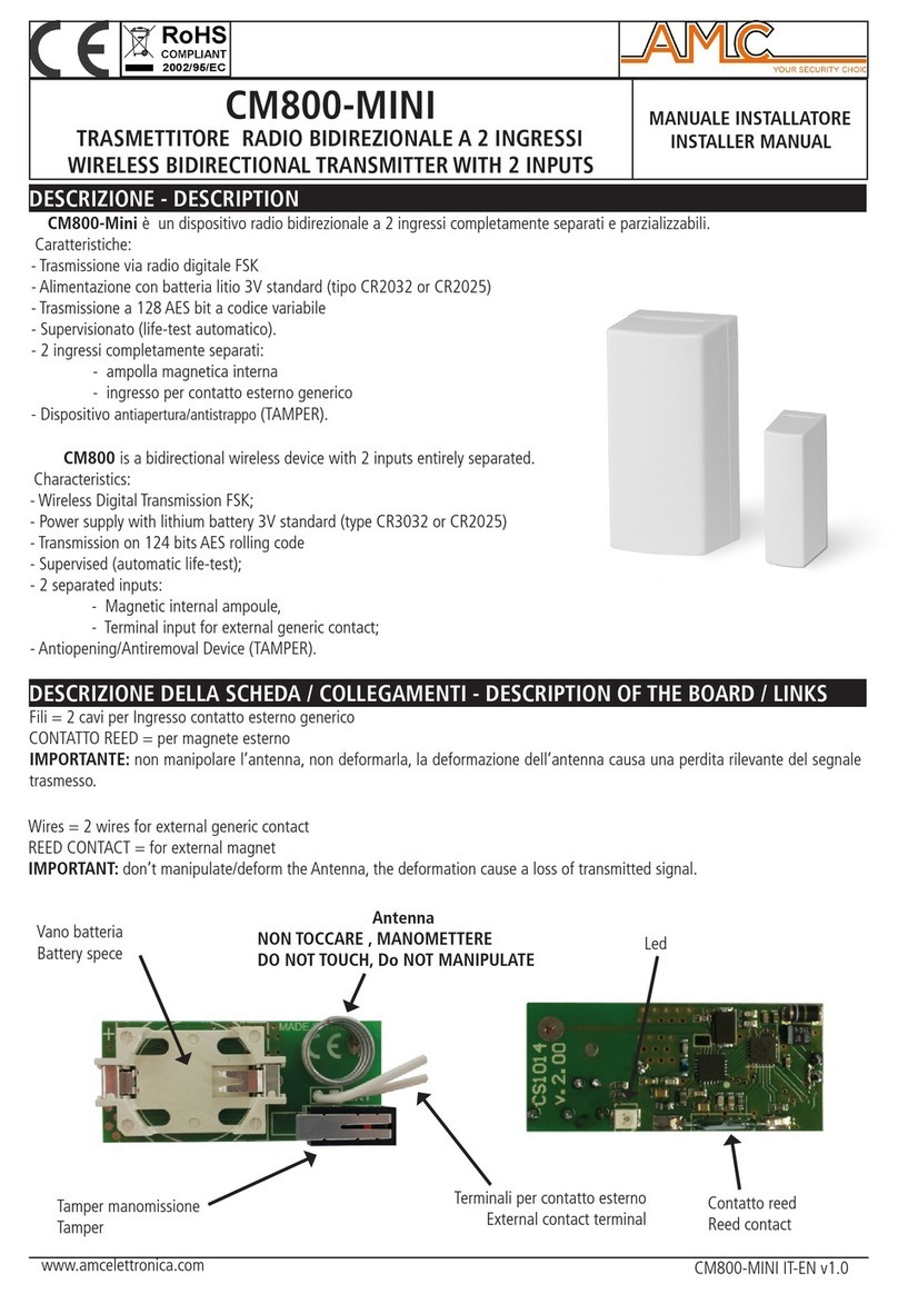
AMC 2751 User manual

2751
Transmitter with
Electrochemical Sensor
INSTRUCTION MANUAL
IMPORTANT:
Please read these installations and operating instructions completely
and carefully before starting.
Filename: 3067405B.doc
Revised: Apr 23, 2007
Copyright ©, April 2004, AMC
The Armstrong Monitoring Corporation
215 Colonnade Road South, Ottawa, Ontario, Canada K2E 7K3
Tel: (613) 225-9531 • Fax: (613) 225-6965 • Canada & U.S. Toll Free: 1-800-465-5777


AMC-2751 Transmitter & Sensor
1
TABLE OF CONTENTS
Section Title Page
1WARRANTY.............................................................................................................3
1.1 LIABILITY........................................................................................................... 3
1.2 PRODUCT RETURN ......................................................................................... 3
1.3 MODIFICATIONS AND SUBSTITUTIONS......................................................... 3
2PRODUCT INFORMATION......................................................................................4
2.1 SENSOR/TRANSMITTER MODULE ................................................................. 4
2.2 FACTORY CALIBRATION ................................................................................. 4
3PRODUCT DESCRIPTION ......................................................................................5
3.1 GENERAL DESCRIPTION................................................................................. 5
3.1.1 SENSOR / TRANSMITTER SPECIFICATIONS......................................................5
3.2 AMC-2751 HOUSING ........................................................................................ 6
4INSTALLATION .......................................................................................................7
4.1 LOCATION AND MOUNTING............................................................................ 7
4.2 CABLE SELECTION AND WIRING ................................................................... 8
4.2.1 SENSOR/TRANSMITTER TO MONITOR WIRING ................................................8
4.2.2 INTERFACING TO COMPUTER OR DATALOGGER ..........................................10
5OPERATION AND CALIBRATION........................................................................11
5.1 OPERATION .................................................................................................... 11
5.2 CALIBRATION ................................................................................................. 11
5.2.1 ON SITE CALIBRATION EQUIPMENT REQUIRED.............................................12
5.2.2 CALIBRATION PROCEDURE ..............................................................................12
6MAINTENANCE.....................................................................................................14
6.1 GENERAL........................................................................................................ 14
6.2 SCHEDULED CALIBRATION .......................................................................... 14
6.3 SENSOR/TRANSMITTER REPLACEMENT.................................................... 14

AMC-2751 Transmitter & Sensor
2

AMC-2751 Transmitter & Sensor
3
1WARRANTY
The AMC-2751 transmitter is warranted against defects in material and workmanship for a
period of two years from date of delivery. Maintenance items are not warranted. During the
warranty period, The Armstrong Monitoring Corporation will repair or replace components that
prove to be defective in the opinion of AMC. Any equipment deemed to be defective by the user
should be returned to The Armstrong Monitoring Corporation for evaluation (see product return
below). Site visits by Armstrong personnel, to evaluate/repair equipment, are not covered
by this warranty. AMC is not liable for auxiliary interfaced equipment, nor for consequential
damage. This warranty shall not apply to any product, which has been modified in any way,
which has been repaired by any other party other than a qualified technician or authorized AMC
representative, or when failure is due to misuse or conditions of use.
Note: extended warranty mail in calibration programs are available (please call 1-800-465-
5777).
1.1 LIABILITY
All AMC products must be installed and maintained according to instructions. Only qualified
personnel should install and maintain the equipment.
AMC shall have no liability arising from auxiliary interfaced equipment, for consequential
damage, or the installation and operation of this equipment. AMC shall have no liability for
labour or freight costs, or any other costs or charges in excess of the amount of the invoice for
the products.
THIS WARRANTY IS IN LIEU OF ALL OTHER WARRANTIES, EXPRESSED OR IMPLIED,
AND SPECIFICALLY THE WARRANTIES OF MERCHANTABILITY AND FITNESS FOR A
PARTICULAR PURPOSE. THERE ARE NO WARRANTIES THAT EXTEND BEYOND THE
DESCRIPTION ON THE FACE THEREOF.
WARNING
CHECK TO ASSURE THE WORKING AREA IS FREE FROM HAZARDS DURING
INSTALLATION OR WHEN PERFORMING MAINTENANCE, AND USE PROPER
PRECAUTIONS.
1.2 PRODUCT RETURN
All products returned for warranty or service should be shipped by prepaid freight and will be
accepted only with RMA or repair number issued by AMC. All products returned to the client will
be shipped by freight collect.
1.3 MODIFICATIONS AND SUBSTITUTIONS
Due to an ongoing development program, AMC reserves the right to substitute components and
change specifications at any time without incurring any obligations.

AMC-2751 Transmitter & Sensor
4
2PRODUCT INFORMATION
2.1 SENSOR/TRANSMITTER MODULE
Sensor/transmitter unit order number. ……………………
AMC-2751
Sensor/transmitter serial number..………………………..
Transmitter board with display order number ……….…..
Sensor order number..…………………….……..……… …
AMC 91AG
Sensor Date Code………………………………….………..
Power Supply Requirement………………………………….
12 to 24 VDC @ 20 mA
Sensor Warranty……………………………………………..
3 years
2.2 FACTORY CALIBRATION
Gas Type………………………………………………..….….
CO
Zero Gas, at 4 mA Signal…………….………………..……. Air
Gas Concentration at 20 mA Signal………………………...
Calibration Adapter Part Number……………………………
Note:
All Armstrong Monitoring systems must be installed and maintained according to
instructions to assure proper operation. Only qualified technicians should install and
maintain the equipment. For re-calibration extended warranty program information
please call 1-800-465-5777.

AMC-2751 Transmitter & Sensor
5
3PRODUCT DESCRIPTION
3.1 GENERAL DESCRIPTION
The AMC-2751 sensor/transmitter unit is designed to provide continuous, reliable surveillance of
surrounding air for the target gas listed in the Factory Settings (Section 2.2). This unit provides
a 4 to 20 mA, variable current signal, which is proportional to the gas concentration detected.
Each sensor/transmitter unit is factory calibrated, and is ready for field installation and
operation.
3.1.1 SENSOR / TRANSMITTER SPECIFICATIONS
SENSOR ORDER NUMBER
AMC 91AG
SENSOR TYPE & GAS: Electrochemical cell for carbon monoxide.
GAS RANGES
0-100 ppm CO □, 0-200 ppm CO □,
0-300 ppm CO □, 0-400 ppm CO □
SENSOR RESPONSE TIME: Better than 90% step change in 45 seconds @ 20ºC
EXPECTED SENSOR LIFE: Greater than 4 years
SENSOR/TRANSMITTER
OPERATING TEMPERATURE:
-20ºC to 40ºC
SENSOR/TRANSMITTER
HUMIDITY RANGE:
15 to 90% RH, non-condensing (constant)
0 to 98% RH, non-condensing (intermittent)
SENSOR/TRANSMITTER SIGNAL:
4 to 20ma
SIGNAL LINEARITY:
Linear to the concentration of gas

AMC-2751 Transmitter & Sensor
6
3.2 AMC-2751 HOUSING
The AMC-2751 sensor/transmitter unit is enclosed in an ABS housing as shown in Figure 1.
This housing is suitable for use in parking and service garages where the unit is not exposed to
rain or direct sunlight.
PVC HOUSING
Round PVC housing with cover.
For use in non-hazardous areas.
Provided with water resistant gasket.
AMC 2751
Carbon Monoxide
FIGURE 1: AMC-2751 Housing

AMC-2751 Transmitter & Sensor
7
4INSTALLATION
4.1 LOCATION AND MOUNTING
Mount the AMC-2751 sensor/transmitter on a solid, non-vibrating surface or structure in an area
where the ambient concentration of gas is not directly affected by the presence of clean air
supply, ventilation systems, blockage by surrounding articles and sources of interference
gases. Reading will be affected by presence of hydrogen gas, ethanol and nitrogen dioxide (500
ppm of hydrogen will cause 200 ppm CO reading, 2000 ppm of ethanol will cause less than 30
ppm CO reading, 30 ppm of nitrogen dioxide will cause less than 10 ppm CO reading). Please,
refer to local codes for further sensor/transmitter installation information.
The installer is required to provide any mounting hardware that may be required.
The AMC-2751 sensor/transmitter circuit board with sensor is removable from the enclosure for
ease of installation.
Important Notes:
Mount enclosure with the sensor located as per figure 2. This will ensure correct
orientation. Where possible it is recommended to turn off supply power before
removing or replacing the transmitter or sensor.
MOUNTING
SCREW
MOUNTING
SCREW
SIDE VIEW
AMC 2751
Carbon Monoxide
3/4" Ø CONDUIT
Wiring
SENSOR
TRANSMITTER
FIGURE 2: Mounting of AMC-2751 Sensor/Transmitter Unit

AMC-2751 Transmitter & Sensor
8
4.2 CABLE SELECTION AND WIRING
To pass the 4 to 20mA signal from the AMC-2751 sensor/transmitter to the monitor, a two conductor,
shielded cable is recommended. Note that the same wire pair can be used for both signal and power due
to the low power current loop design of the AMC-2751. For best signal transmission and maximum noise
rejection, it is recommended to run the cable through steel conduit ( the cable must be grounded at the
monitor or power supply).
The AMC-2751 minimum stated voltage requirement of 12 VDC is based on the use of a 250 ohm load
resistor to covert the current signal into a voltage signal. The maximum Cable Distance Chart (Figure 3)
assumes the use of a 250 ohm load resistor, and a safety margin of .5 VDC. It gives absolute maximum
cable lengths for a range of wire gauges. Note that the user must take responsibility for the selection of
wire gage, power supply voltage and load resistor used as the values shown may not be suitable for all
applications.
WIRE GAUGE
AWG
R/1000 ft
22
16.2 ohms 20
10.3 ohms 18
6.5 ohms 16
4.3 ohms
@12VDC 400
(120)
700
(210)
1000
(300)
1500
(4500)
MAXIMUM
DISTANCE IN
FEET
(METERS) @24VDC 10000
(3000)
16000
(4800)
Over 20000
(6000)
Over 20000
(6000)
FIGURE 3: Cable Selection Chart (Based on 250 Ohm Load Resistor & VSM = .5 V)
4.2.1 SENSOR/TRANSMITTER TO MONITOR WIRING
The AMC-2751 sensor/transmitter should be connected to the monitor, as shown in Figure 4, by
a twisted pair cable for the conduction of the 4 to 20 mA signal.
See the following connections going from the AMC-2751 to the monitor for each channel:
AMC-2751 Terminal (+) -------- goes to------- Monitor Channel Terminal (+)
AMC-2751 Terminal (-) -------- goes to------- Monitor Channel Terminal (SIG)

AMC-2751 Transmitter & Sensor
9
CONDUIT
TRANSMITTER CIRCUIT
BOARDVIEW
TRANSMITTER
WHITE
BLACK
SIG
+
-
MONITOR
+
-
WHITE
BLACK
TRANSMITTER TERMINAL BLOCK
WARNING 1
TRANSMITTER ( - ) TERMINAL
CONNECTS TO MONITOR
SIG (SIG) TERMINAL.
WARNING 2
CABLE SHIELD MUST
NOT BE USED AS A
CONDUCTOR.
12 TO 27 VDC SHIELD
FIGURE 4: Sensor/Transmitter to Monitor Wiring Layout

AMC-2751 Transmitter & Sensor
10
4.2.2 INTERFACING TO COMPUTER OR DATALOGGER
The signal output of the AMC-2751 sensor/transmitter is a 4 to 20 mA DC current, therefore
it can be connected to computers or data-loggers equipped with an analog-to-digital converter.
In many cases a load resistor is required to convert the 4 to 20 ma current signal to a voltage
signal, as shown in Figure 5.
CONDUIT
WHITE
BLACK
TRANSMITTER
FILTERED
12 - 27 VDC
SUPPLY
COMPUTER
DATALOGGER
OR NON-AMC
MONITOR
LOAD
RESISTANCE
FOR VOLTAGE
MEASUREMENT
-
+
-
+
SIGNAL
POWER
{
{
SHIELD
FIGURE 5: Interfacing to Computer or Data-logger

AMC-2751 Transmitter & Sensor
11
5OPERATION AND CALIBRATION
5.1 OPERATION
The AMC-2751 sensor/transmitter is factory calibrated for the gas listed in the Product
Information (Section 2) at the beginning of this manual. The sensor/transmitter should not
require re-calibration when first installed and powered up, but a test for correct operation is
recommended after a stabilization period of 30 minutes.
In clean air, after the stabilization period, the transmitter should be sending a signal of
approximately 4 mA to the monitor or controller. It can be expected, in most cases, that
presence of CO will be indicated. Background air contains 1-3 ppm of CO typically.
Although the electrochemical sensors are very selective, there are some interference gases,
which can also cause a response from the sensor. See section 4.1 for list of interference gases.
In the case of large signal variations (in a clean air environment), check for an installation
problem or the possibility of an interference gas being present.
5.2 CALIBRATION
Every AMC-2751 sensor/transmitter is factory calibrated, so each unit should be ready for
operation after installation and a 30 minute stabilization time.
Subsequent calibration is required as a part of regular maintenance, and when replacing the
sensor. See the maintenance section of this manual for the recommended calibration schedule.
Caution:
- Only qualified personnel should perform the actual calibration.
- Users new to gas calibration are advised to consult with Armstrong Monitoring
The Armstrong Monitoring Corporation offers the following plans:
1. Factory pre-calibrated replacement sensor/transmitter units
2. On site installation and calibration by Armstrong Monitoring
3. On site calibration by Armstrong Monitoring
4. Training by Armstrong Monitoring
5. Extended warranty calibration program

AMC-2751 Transmitter & Sensor
12
5.2.1 ON SITE CALIBRATION EQUIPMENT REQUIRED
For qualified personnel, the following is a recommended list of calibration equipment required.
•A digital multi-meter with a range of 20.0 mA or more and 200 mV or more.
•A “Remote Calibration Lead” (P/N 2900-01) for the above meter ( available from AMC )
•A set of leads with clip on probes for the above meter
•Miniature screwdriver trimmer adjustment tool
•Calibration adapter, available from AMC
•Zero & Span gases ( contact AMC for information )
•Clean, low static cloth or tissue to cover sides of sensor during calibration
5.2.2 CALIBRATION PROCEDURE
The transmitter is equipped with a remote calibration feature allowing for one-man calibration at
the transmitter location. The transmitter output is measured using the plug-in type “Remote
Calibration Lead”. In most cases it is only Zero and Span adjustments that are made in field
calibrations.
Note:
The calibration procedure may cause false alarm and or fail signal. Appropriate
precautions may be required.
Refer to Figure 6 to perform the following calibration procedure:
1) Remove cover from transmitter housing.
2) Attach and set the multi-meters as shown.
3) Cover the sides of sensor with a clean cloth or similar to prevent a draft on the
sensor.
4) Apply a Zero gas sample, with a calibration adapter cup firmly and completely over
the sensor opening on side of AMC-2751 for 2 minutes with a flow rate of .5 liters per
minute.
5) At 2 minutes adjust the Zero trimmer for a zero current of 4.00 mA +/- .1ma. Note
that the zero current may give a signal representing a gas concentration as high as
2ppm depending on the zero gas used.
6) Apply the Span gas sample, with a calibration adapter cup firmly and completely over
the sensor opening on side of AMC-2751 for 2 minutes with a flow rate of .5 liters per
minute.
7) At 2 minutes adjust the Span trimmer for the Span current reading of 20 ma +/- .16
mA.

AMC-2751 Transmitter & Sensor
13
TRANSMITTER
CAL JACK
ZERO ADJUST
SPAN ADJUST
SENSOR
CALIBRATION ADAPTER
ZERO & SPAN GASES
12.000
DIGITAL MULTIMETER
CURRENT ADJUST
+050.0
PCB
SIG G
G2
Set scale for 20 mA or more. Set scale for 200 mV or more.
Use "Clip On" type lead
to take voltage measurements.
ADAPTER
+
INSERT REMOTE
CAL LEAD
INTO CAL JACK
FIGURE 6: Calibration Procedure

AMC-2751 Transmitter & Sensor
14
6MAINTENANCE
6.1 GENERAL
The AMC-2751 sensor/transmitter unit should be brushed or wiped as required, depending on
the rate of accumulation of any dust or dirt.
To avoid sensor damage, the unit MUST NOT be submerged in any liquids. Hosing or
splashing of the unit with any liquids must also be avoided.
6.2 SCHEDULED CALIBRATION
Scheduled calibration is critical in maintaining proper function of gas sensor/transmitters.
It is recommended that the AMC-2751 be calibrated a minimum of twice a year.
As mentioned, Armstrong Monitoring offers a number of different maintenance plans to suit your
requirements.
6.3 SENSOR/TRANSMITTER REPLACEMENT
The sensor life of the AMC-2751 is typically over 4 years. When its signal is greatly reduced or
unstable, the sensor replacement is required.
Please note that the sensor itself is not replaceable. To replace the circuit card with the sensor,
please contact the factory.
Caution:
It is recommended to turn off the power to the sensor transmitter before replacing the
board.
Note:
15 minutes (minimum) is required for a new sensor to stabilize before calibration.
30 minutes to 1 hour is recommended.
Table of contents
Other AMC Transmitter manuals