Pfeiffer TC 110 PB User manual

PT 0245 BEN/J (1710)
OPERATING INSTRUCTIONS EN
Translation of the original instructions
TC 110 PB
Electronic Drive Unit

Table of contents
2
Table of contents
1 About this manual. . . . . . . . . . . . . . . . . . . . . . . . . . . . . . . . . . . . . . . . . . . . . . . 4
1.1 Validity. . . . . . . . . . . . . . . . . . . . . . . . . . . . . . . . . . . . . . . . . . . . . . . . . . . . . 4
1.2 Conventions . . . . . . . . . . . . . . . . . . . . . . . . . . . . . . . . . . . . . . . . . . . . . . . . 4
1.2.1 Safety instructions. . . . . . . . . . . . . . . . . . . . . . . . . . . . . . . . . . . . . . 4
1.2.2 Pictographs . . . . . . . . . . . . . . . . . . . . . . . . . . . . . . . . . . . . . . . . . . . 5
1.2.3 Instructions in the text . . . . . . . . . . . . . . . . . . . . . . . . . . . . . . . . . . . 5
1.2.4 Abbreviations . . . . . . . . . . . . . . . . . . . . . . . . . . . . . . . . . . . . . . . . . 5
2 Safety . . . . . . . . . . . . . . . . . . . . . . . . . . . . . . . . . . . . . . . . . . . . . . . . . . . . . . . . . 6
2.1 Safety precautions . . . . . . . . . . . . . . . . . . . . . . . . . . . . . . . . . . . . . . . . . . . 6
2.2 Proper use . . . . . . . . . . . . . . . . . . . . . . . . . . . . . . . . . . . . . . . . . . . . . . . . . 7
2.3 Improper use. . . . . . . . . . . . . . . . . . . . . . . . . . . . . . . . . . . . . . . . . . . . . . . . 7
2.4 Functional safety. . . . . . . . . . . . . . . . . . . . . . . . . . . . . . . . . . . . . . . . . . . . . 7
3 Product description. . . . . . . . . . . . . . . . . . . . . . . . . . . . . . . . . . . . . . . . . . . . . . 8
3.1 Product identification. . . . . . . . . . . . . . . . . . . . . . . . . . . . . . . . . . . . . . . . . . 8
3.1.1 Product characteristics . . . . . . . . . . . . . . . . . . . . . . . . . . . . . . . . . . 8
3.1.2 Scope of delivery. . . . . . . . . . . . . . . . . . . . . . . . . . . . . . . . . . . . . . . 8
3.2 Range of application . . . . . . . . . . . . . . . . . . . . . . . . . . . . . . . . . . . . . . . . . . 8
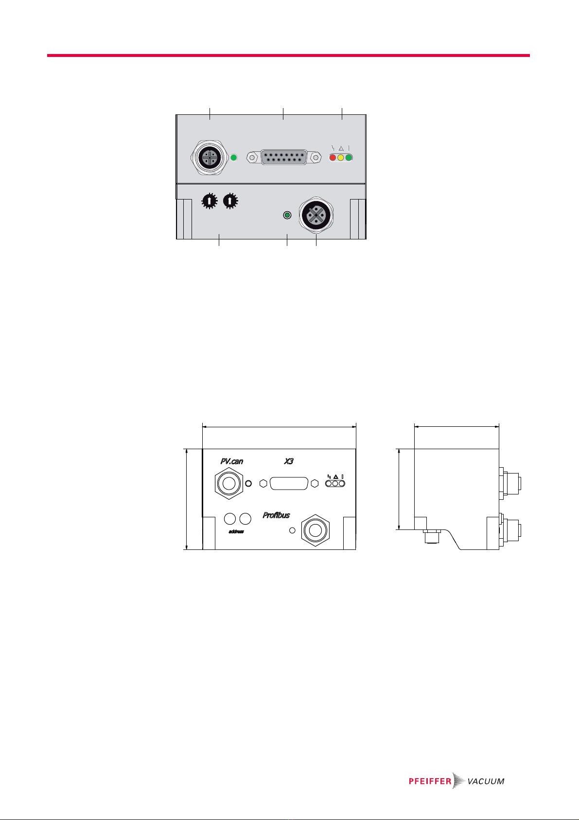
3.3 Function . . . . . . . . . . . . . . . . . . . . . . . . . . . . . . . . . . . . . . . . . . . . . . . . . . . 9
3.4 Dimensions . . . . . . . . . . . . . . . . . . . . . . . . . . . . . . . . . . . . . . . . . . . . . . . . . 9
3.5 General connection description . . . . . . . . . . . . . . . . . . . . . . . . . . . . . . . . 10
3.6 Accessory connection . . . . . . . . . . . . . . . . . . . . . . . . . . . . . . . . . . . . . . . . 10
4 Connection diagram . . . . . . . . . . . . . . . . . . . . . . . . . . . . . . . . . . . . . . . . . . . . 11
5 Connection "Profibus" . . . . . . . . . . . . . . . . . . . . . . . . . . . . . . . . . . . . . . . . . . 12
5.1 Connections . . . . . . . . . . . . . . . . . . . . . . . . . . . . . . . . . . . . . . . . . . . . . . . 12
5.2 Configuring the connection . . . . . . . . . . . . . . . . . . . . . . . . . . . . . . . . . . . . 12
5.2.1 Profibus status LED . . . . . . . . . . . . . . . . . . . . . . . . . . . . . . . . . . . 12
5.3 Modules . . . . . . . . . . . . . . . . . . . . . . . . . . . . . . . . . . . . . . . . . . . . . . . . . . 12
5.3.1 PPO1. . . . . . . . . . . . . . . . . . . . . . . . . . . . . . . . . . . . . . . . . . . . . . . 13
5.3.2 PPO3. . . . . . . . . . . . . . . . . . . . . . . . . . . . . . . . . . . . . . . . . . . . . . . 14
5.3.3 control-/status word. . . . . . . . . . . . . . . . . . . . . . . . . . . . . . . . . . . . 14
5.3.4 control-/status byte . . . . . . . . . . . . . . . . . . . . . . . . . . . . . . . . . . . . 15
5.3.5 Parameterization data . . . . . . . . . . . . . . . . . . . . . . . . . . . . . . . . . . 15
5.4 Expanded diagnostics data. . . . . . . . . . . . . . . . . . . . . . . . . . . . . . . . . . . . 15
6 Connection "X3" . . . . . . . . . . . . . . . . . . . . . . . . . . . . . . . . . . . . . . . . . . . . . . . 16
6.1 Pin assignment . . . . . . . . . . . . . . . . . . . . . . . . . . . . . . . . . . . . . . . . . . . . . 16
6.2 Operation via "X3" connection . . . . . . . . . . . . . . . . . . . . . . . . . . . . . . . . . 16
6.2.1 Voltage supply. . . . . . . . . . . . . . . . . . . . . . . . . . . . . . . . . . . . . . . . 16
6.2.2 Inputs . . . . . . . . . . . . . . . . . . . . . . . . . . . . . . . . . . . . . . . . . . . . . . 17
6.2.3 Outputs . . . . . . . . . . . . . . . . . . . . . . . . . . . . . . . . . . . . . . . . . . . . . 17
6.2.4 RS-485 . . . . . . . . . . . . . . . . . . . . . . . . . . . . . . . . . . . . . . . . . . . . . 18
7 The Pfeiffer Vacuum parameter set . . . . . . . . . . . . . . . . . . . . . . . . . . . . . . . . 19
7.1 General . . . . . . . . . . . . . . . . . . . . . . . . . . . . . . . . . . . . . . . . . . . . . . . . . . . 19
7.1.1 Conventions . . . . . . . . . . . . . . . . . . . . . . . . . . . . . . . . . . . . . . . . . 19
7.2 Parameter overview . . . . . . . . . . . . . . . . . . . . . . . . . . . . . . . . . . . . . . . . . 19
7.2.1 Annotation . . . . . . . . . . . . . . . . . . . . . . . . . . . . . . . . . . . . . . . . . . . 19
7.2.2 Operation with DCU . . . . . . . . . . . . . . . . . . . . . . . . . . . . . . . . . . . 19
7.2.3 Only for Profibus . . . . . . . . . . . . . . . . . . . . . . . . . . . . . . . . . . . . . . 20
7.2.4 Control commands . . . . . . . . . . . . . . . . . . . . . . . . . . . . . . . . . . . . 20
7.2.5 Status requests . . . . . . . . . . . . . . . . . . . . . . . . . . . . . . . . . . . . . . . 21
7.2.6 Set value settings . . . . . . . . . . . . . . . . . . . . . . . . . . . . . . . . . . . . . 22
7.3 Configuring the connections . . . . . . . . . . . . . . . . . . . . . . . . . . . . . . . . . . . 22

Table of contents
3
7.3.1 Digital outputs on "X3" . . . . . . . . . . . . . . . . . . . . . . . . . . . . . . . . . 22
7.3.2 Accessory connection . . . . . . . . . . . . . . . . . . . . . . . . . . . . . . . . . . 23
7.3.3 Analog output on "X3" . . . . . . . . . . . . . . . . . . . . . . . . . . . . . . . . . . 23
7.3.4 Control via interface . . . . . . . . . . . . . . . . . . . . . . . . . . . . . . . . . . . 24
7.3.5 Digital inputs on "X3". . . . . . . . . . . . . . . . . . . . . . . . . . . . . . . . . . . 24
7.4 Operation with the Pfeiffer Vacuum parameter set . . . . . . . . . . . . . . . . . . 24
7.4.1 Factory settings. . . . . . . . . . . . . . . . . . . . . . . . . . . . . . . . . . . . . . . 24
7.4.2 Checking the adjustments. . . . . . . . . . . . . . . . . . . . . . . . . . . . . . . 24
7.4.3 Gas type dependent operations . . . . . . . . . . . . . . . . . . . . . . . . . . 24
7.4.4 Set value power consumption . . . . . . . . . . . . . . . . . . . . . . . . . . . . 25
7.4.5 Run-up time. . . . . . . . . . . . . . . . . . . . . . . . . . . . . . . . . . . . . . . . . . 25
7.4.6 Adjusting the rotation speed switchpoint. . . . . . . . . . . . . . . . . . . . 26
7.4.7 Rotation speed setting mode . . . . . . . . . . . . . . . . . . . . . . . . . . . . 27
7.4.8 Standby . . . . . . . . . . . . . . . . . . . . . . . . . . . . . . . . . . . . . . . . . . . . . 27
7.4.9 Rotation speed set value. . . . . . . . . . . . . . . . . . . . . . . . . . . . . . . . 27
7.4.10 Operation mode backing pump . . . . . . . . . . . . . . . . . . . . . . . . . . . 28
7.4.11 Operation with accessories. . . . . . . . . . . . . . . . . . . . . . . . . . . . . . 29
7.4.12 Vent modes . . . . . . . . . . . . . . . . . . . . . . . . . . . . . . . . . . . . . . . . . . 29
7.4.13 Monitoring the thermal load. . . . . . . . . . . . . . . . . . . . . . . . . . . . . . 30
7.5 Switching on/off the pump. . . . . . . . . . . . . . . . . . . . . . . . . . . . . . . . . . . . . 30
7.5.1 Switching on . . . . . . . . . . . . . . . . . . . . . . . . . . . . . . . . . . . . . . . . . 30
7.5.2 Switching off . . . . . . . . . . . . . . . . . . . . . . . . . . . . . . . . . . . . . . . . . 30
8 Pfeiffer Vacuum Protocol for "RS-485" . . . . . . . . . . . . . . . . . . . . . . . . . . . . . 31
8.1 Telegram frame . . . . . . . . . . . . . . . . . . . . . . . . . . . . . . . . . . . . . . . . . . . . . 31
8.2 Telegrams . . . . . . . . . . . . . . . . . . . . . . . . . . . . . . . . . . . . . . . . . . . . . . . . . 31
8.2.1 Example 1 . . . . . . . . . . . . . . . . . . . . . . . . . . . . . . . . . . . . . . . . . . . 31
8.2.2 Example 2 . . . . . . . . . . . . . . . . . . . . . . . . . . . . . . . . . . . . . . . . . . . 32
8.3 Applied data types . . . . . . . . . . . . . . . . . . . . . . . . . . . . . . . . . . . . . . . . . . 32
9 Malfunctions . . . . . . . . . . . . . . . . . . . . . . . . . . . . . . . . . . . . . . . . . . . . . . . . . . 33
9.1 General . . . . . . . . . . . . . . . . . . . . . . . . . . . . . . . . . . . . . . . . . . . . . . . . . . . 33
9.2 Operation display via LED . . . . . . . . . . . . . . . . . . . . . . . . . . . . . . . . . . . . 33
9.3 Error codes . . . . . . . . . . . . . . . . . . . . . . . . . . . . . . . . . . . . . . . . . . . . . . . . 33
Declaration of conformity. . . . . . . . . . . . . . . . . . . . . . . . . . . . . . . . . . . . . . . . 36

4
About this manual
1 About this manual
1.1 Validity
This operating manual is for customers of Pfeiffer Vacuum. It describes the functioning
of the designated product and provides the most important information for safe use of
the unit. The description follows applicable EU guidelines. All information provided in this
operating manual refers to the current state of the product's development. The documen-
tation remains valid as long as the customer does not make any changes to the product.
Up-to-date operating instructions can also be downloaded from
www.pfeiffer-vacuum.com.
1.2 Conventions
1.2.1 Safety instructions
The safety instructions in Pfeiffer Vacuum operating instructions are the result of risk
evaluations and hazard analyses and are oriented on international certification stan-
dards as specified by UL, CSA, ANSI Z-535, SEMI S1, ISO 3864 and DIN 4844. In this
document, the following hazard levels and information are considered:
DANGER
Imminent danger
Indicates an imminent hazardous situation that will result in death or serious injury.
WARNING
Possibly imminent danger
Indicates an imminent hazardous situation that can result in death or serious injury.
CAUTION
Possibly imminent danger
Indicates an imminent hazardous situation that can result in minor or moderate injury.
NOTICE
Command or note
Command to perform an action or information about properties, the disregarding of
which may result in damage to the product.

About this manual
5
1.2.2 Pictographs
1.2.3 Instructions in the text
Work instruction: here you have to do something.
1.2.4 Abbreviations
DCU: Display Control Unit
HPU: Handheld Programming Unit
TC: Electronic drive unit for turbopump
PB: Profibus version
TPS: Mains pack
DI / DO: Digital input / digital output
AI / AO: Analog input / analog output
f: Rotation speed (derivated from frequency in Hz)
[P:000]: Parameter of the electronic drive unit with number
Prohibition of an action to avoid any risk of accidents, the disregarding
of which may result in serious accidents
Warning of a displayed source of danger in connection with operation of
the unit or equipment
Command to perform an action or task associated with a source of dan-
ger, the disregarding of which may result in serious accidents
Important information about the product or this document

6
Safety
2Safety
2.1 Safety precautions
●Power supply: The turbopump power supply must apply to the requirements of dou-
ble insulation between mains input voltage and operating voltage according to the reg-
ulations of IEC 61010 and IEC 60950. Therefore Pfeiffer Vacuum recommends to use
exclusively original-power packs and -accessories. Only in this case Pfeiffer Vacuum
is able to guarantee the compliance of the European and North American guidelines.
●Observe all safety and accident prevention regulations.
●A safe connection to the protective earthing conductor (PE) is recommended (protec-
tion class III).
●Regularly check the proper observance of all safety measures.
●Before carrying out any work disconnect the unit and all associated installations safely
from the mains.
●Do not loosen any plug connection during operations.
●The unit has been accredited with protection class IP 30. Take necessary measures
when installing into ambient conditions, which afford other protection classes.
●Keep leads and cables well away from hot surfaces (> 70 °C).
●Only separate the pump and the electronic drive unit from each other after disconnect-
ing the supply voltage and the complete standstill of the pump.
Duty to inform
Each person involved in the installation or operation of the unit must read and observe
the safety-related parts of these operating instuctions.
The operator is obligated to make operating personnel aware of dangers originating
from the unit or the entire system.
WARNING
Danger of unsafe electrical installation
Safe operation after installation is the responsibility of the operator.
Do not independently modify or change the pump and electrical equipment.
Make sure that the system is integrated in an emergency off safety circuit.
Consult Pfeiffer Vacuum for special requirements.
WARNING
Danger of electric shock
In case of defect, the parts connected to the mains supply are under voltage.
Always keep the mains connection freely accessible so that you can disconnect it at
any time.

Safety
7
2.2 Proper use
●The electronic drive unit TC 110 PB operates designated Pfeiffer Vacuum turbopumps
and their accessories in a bus system Profibus-DP.
2.3 Improper use
Improper use will cause all claims for liability and warranties to be forfeited. Improper use
is defined as usage for purposes deviating from those mentioned above, especially:
●use of accessories or spare parts, which are not named in this manual
●operation of the devices in areas with ionizing radiation
2.4 Functional safety
The drive unit (electronic drive unit) TC 110 PB performs the safety function "Safe Limit-
ed Speed" according to EN 61800-5-2. In case of excess rotation speed the commutation
of the pump motor is switched off and the drive transferred into the safe condition.
Summary of characteristic data for use in safety-relevant applications:
●During the expected device life span of up to 20 years no proof test is required.
●If the user calculates his safety application with the specified values for 20 years, the
safety control system must be taken out of operation after 20 years and returned to
the manufacturer. A proof test cannot be accomplished by the user.
NOTICE
EC conformity
The manufacturer's declaration of conformity becomes invalid if the operator modifies
the original product or installs additional components.
Following installation into a plant and before commissioning, the operator must check
the entire system for compliance with the valid EU directives and reassess it accord-
ingly.
warranty seal
Closure seal
The product is sealed at the factory. Damaging or removal of a closure seal leads to the
loss of liability and warranty entitlements.
Do not open the product within its warranty period!
For process-related shorter maintenance intervals please contact the Pfeiffer Vacu-
um Service.
Characteristics according to IEC 61508 and IEC 62061
Characteristic Safety Integrity Level PFH PFDav Proof Test Interval T
Value SIL CL 2 4.2 * 10-9 / h 3.7 * 10-4 20 a
Characteristics according to EN ISO 13849-1
Characteristic Performance Level Category MTTFdAverage Diagnostic Coverage DC
Value PL d Cat. 3 high (134 a) medium (90 % - <99 %)

8
Product description
3 Product description
3.1 Product identification
This product has been tested to the requirements of CAN/CSA-C22.2 No. 61010-1, sec-
ond edition, including Amendment 1, or a later version of the same standard incorporat-
ing the same level of testing requirements.
For information about other certifications, if applicable, please see the signet on the prod-
uct or:
●www.tuvdotcom.com
●TUVdotCOM-ID 0000021320
3.1.1 Product characteristics
The electronic drive unit TC 110 PB is an integrated component of the turbopump. It's
purpose is to drive, monitor and control the entire pump.
To correctly identify the product when communicating with Pfeiffer Vacuum, always have
the information from the rating plate available.
Fig. 1: Example for a rating plate
3.1.2 Scope of delivery
●CD-ROM for Profibus connection with GSD file
3.2 Range of application
Pfeiffer Vacuum electronic drive units TC 110 PB must be installed and operated in the
following ambient conditions.
Characteristics TC 110 PB
Connection voltage TC 24 V DC
Connection panel Profibus
Turbopump HiPace 10, 30, 80, 300, SplitFlow 50
Mod.:
M.-No.:
Ser. -No.:
Oil:
S(N
2
):
n,f:
Made in Germany
HiPace 300
DN 100 ISO-K, 3P
PM P03 900
---
260 l/s
60000 1/min, 1000 Hz
Weight: 6.7 kg
D-35614 Asslar
Installation location weather protected (indoors)
Protection category IP 30
Protection class III
Temperature +5 °C to +40 °C (up to +35 °C with air cooling)
Relative humidity max. 80 %, at T ≤31 °C, up to max. 50% at T ≤40 °C
Atmospheric pressure 750 hPa - 1060 hPa
Installation altitude 5000 m max.
Degree of pollution 2
Overvoltage category II

Product description
9
3.3 Function
3.4 Dimensions
The TC 110 PB electronic drive unit has the dimensions given below, differing from the
standard TC 110 unit.
Take into account any turbopump installation dimensions differing from those in their
operating manual.
Fig. 2: Profibus panel or the TC 110 PB
b Connections "accessory A+B" (not shown)
c Connection "X3"
d Service connection "PV.can"
f Connection "Profibus"
f1 Status LED "Profibus"
f2 Address selection switches
h Operation monitoring LED
02
4
6
8
10
12
02
4
6
8
address
x10 x1
PV.can X3
Profibus
dc
f2 ff1
h
100 55
52.4
65.4

10
Product description
3.5 General connection description
3.6 Accessory connection
The electronic drive unit is equipped with 4 accessory ports additionally.
Table 1: Overview of factory preset accessory connections on the TC 110 PB
PV.can
M12 casing socket with screw coupling and LED for the connection of an integrated
pressure measurement and for Pfeiffer Vacuum Service purposes.
X3
D-sub 15 pole female socket for the connection of a remote control.
Profibus
M12 socket (B-coded) with screw coupling and LED for the connection of a Profibus
DP bus system.
accessory
M8 socket with screw coupling for the connection of Pfeiffer Vacuum accessories.
Casing socket on the rear side of the electronic drive unit for the connection to the
turbopump.
Plug the control lead of the accessory into the cor-
responding connection of the electronic drive unit.
Configure the accessory connection according to
the parameter set (see p. 22, chap. 7.3). Factory
settings:
•acc. A1 = Air cooling
•acc. A2 = Backing pump
•acc. B1 = Venting valve
•acc. B2 = Casing heating

Connection diagram
11
4 Connection diagram
Fig. 3: Connection diagram and assignment of the TC 110 PB
2
3
4
5
6
7
10
11
8
9
12
13
14
15
1
1
8
9
15
X3
TC 110 PB
DI Remote Priority
DI1
DI2
DI Pumping station
DI Standby
24 VDC* (V+)
Accessory A1
Accessory B1
DO1
DO2
AO1
RS 485 D+
RS 485 D-
+U
B
FE
1
3
4
acc. B2
4
3
1
1
3
4
acc. A2
4
3
1
1
3
4
acc. B1
4
3
1
4
3
1
1
3
4
acc. A1
PV.can
3
1
24
Profibus
1
2
3
4
5
+5VDC** out
RxD/TxD-N
RxD/TxD-P
n.c.
GND**
n.c.
Accessory B2
GND*
n.c.
Accessory A2
GND*
n.c.
Accessory B1
GND*
n.c.
Accessory A1
GND*
Contact load for accessories per connection: 200 mA max.
+U
B
PE
A
B
C
DC in
1
2
3
4
5
24 VDC*
RS 485 +
RS 485 -
n.c.
RS-485
34
21
A
B
C
2
3
4
5
6
7
10
11
8
9
12
13
14
15
1
S2
S1
Connection cable
to power supply TPS/DCU
0 - 10 VDC
= 0 - 100 % *f
end
R ≥ 10kW
90 - 132 /
185 - 265
VAC
2
3
4
5
6
7
10
11
8
9
12
13
14
15
1
+U
B
PE
B
A
C
TPS 110 / 180
DCU 110 / 180
24 VDC / max. 200 mA
24 VDC / max. 50mA
24 VDC / max. 50mA
+24 VDC / 4.6 - 6.3 A ± 10 %
FE
Mains input/
Power supply
External connection
Contact load
max. 6 mA / contact
Fan
Venting
valve
Relay
Fan
Venting
valve
Relay
DC out AC in

12
Connection "Profibus"
5 Connection "Profibus"
5.1 Connections
The connection to a Profibus-DP system is possible via the connection designated "Pro-
fibus" (M12, B-coded). The interface is electrically isolated from the maximum supply
voltage.
Make Profibus connection using suitable Pfeiffer Vacuum accessories and cabling in
compliance with the valid regulations.
5.2 Configuring the connection
To start Profibus communication, the TC 110 PB must be configured by a Profibus master
using the GSD file.
Set a valid and unique Profibus interface address in decimal coding (1-125) using the
address selector switches.
– A new address is adopted only after a restart (supply voltage "Off/On").
Fit rubber plugs at the address selector switches evenly and as deep as possible to
achieve the stated protection class.
5.2.1 Profibus status LED
5.3 Modules
Precisely one of the following modules can be used:
●Data format is always "high word/byte first" (Motorola)
●All Pfeiffer Vacuum parameters of data type 0, 1, 2 and 7 can be used for the param-
eter channel (PPO1) and the parameterization data.
– Additionally the Pfeiffer Vacuum parameters [P:303], [P:360] to [P:369] provide er-
ror codes according to their coding (see p. 15, chap. 5.4).
– Pfeiffer Vacuum parameter [P:349] provides the value 0xAC20C210.
– Avoid conflicts with existing functions!
1
2
3
4
5
Pin Assignment
1+5VDC**
2RxD/TxD-N
3 GND** (for Pin 1)
4RxD/TxD-P
5 not connected
State within 1s Meaning
Off Profibus on device side not active
Green flashing Baud rate detected, no user data exchange
2 x green flashing Fail-safe
Illuminated green User data exchange
Red flashing No Baud rate detected
2 x red flashing Parameterization/configuration data incorrect
Illuminated red Profibus not possible (invalid address, initialisation error)
Module Description I data
(byte) O data
(byte)
PPO1 Control/status bits, rotation speed set and actual value,
noncyclical parameter access
12 12
PPO3 Control/status bits, rotation speed set and actual value 4 4
control-/status word Control/status bits 2 2
control-/status byte Control/status bits 1 1

Connection "Profibus"
13
●Access to the functions in the modules can be influenced by connecting the electronic
drive unit externally (e.g. remotely).
●Output data describe the data communication from the master (e.g. PLC) to the elec-
tronic drive unit.
●Input data describe the data communication from the electronic drive unit to the mas-
ter (e.g. PLC).
5.3.1 PPO1
Parameter channel
Request (output data)
Response (input data)
Control word/status word
Byte Output data (12 bytes) Input data (12 bytes)
0-7 Parameter channel with request Parameter channel with response
8-9 Control word Status word
10-11 Target value in rotation speed setting mode (Hz) Actual rotation speed (Hz)
Byte 0 1 2-3 4-7
Bit76543210
Request/response 0 Parameter number, bit 0 Parameter
value
109876543210
Value Description Corresponding response
0 No request 0
1 Read parameter value 2 or 7 (for data type 0, 1 or 7)
7 or 11 (for data type 2)
3 Write parameter value as integer 2, 7 or 8
10 Write parameter value (only data type 2) as a
round to nearest number value to IEEE 754
7, 8 or 11
Value Description
0 No response
2 Transfer parameter value as integer
7 Request not executable, value contains error number*
8 No operation possible via Profibus
11 Transfer parameter value as a round to nearest number to IEEE 754
*Error number Description
0 Invalid parameter number
Function already used in control word
1 Parameter value not changeable
2 Below/above value range
5 Incorrect data type
101 Invalid request
102 Parameter value not readable
103 Invalid format
Bit Output data Input data
15 - Reserved (do not evaluate)
14 - Reserved (do not evaluate)
13 - 0
12 Enable venting 0
11 Heating Pump rotates
10 Enable process data (control word and parame-
ter channel):
0 = ignore
1 = accept
Set rotation speed attained
9 - Process data enabled

14
Connection "Profibus"
5.3.2 PPO3
5.3.3 control-/status word
8 Standby Rotation speed switch point attained
7 Error acknowledgement; -> automatic trip
switch
Warning
6 Rotation speed setting mode Automatic trip switch (switching back on only by
pumping station off and back on)
5- 1
4- 1
3- Errors
2 - Operation (no error, pumping station and motor
pumps are on, no automatic trip switch)
1- 0
0 Pumping station Standby (no error, no automatic trip switch, en-
able process data)
Bit Output data Input data
Byte Output data (4 byte) Input data (4 byte)
0-1 Control word (see PPO1) Status word (see PPO1)
2-3 Target value in rotation speed setting mode (Hz) Actual rotation speed (Hz)
Byte Output data (2 byte) Input data (2 byte)
0-1 Control word (see PPO1) Status word (see PPO1)

Connection "Profibus"
15
5.3.4 control-/status byte
5.3.5 Parameterization data
To set a configuration that deviates from the delivery state (="start-up configuration") or
to define actions in the Profibus "fail-safe" state and/or when response monitoring lapses
(e.g. master fails) (="fail-safe action"), up to six parameters, described with predefined
values on a case-by-case basis, can be defined for all modules. Eight-byte parameter-
ization data are added per parameter in the following format (undefined points to be as-
signed 0):
5.4 Expanded diagnostics data
*Device errors and warnings are anchored in the electronic drive unit (see p. 33, chap.
9.3).
** see PPO1
Bit Output data (1 byte) Input data (1 byte)
7 Error acknowledgement, -> automatic trip
switch (switching back on only by pumping sta-
tion off and back on)
Warning, general
6 Standby Warning, temperature
5 Enable venting Operation: No error, pumping station and motor
pump are on, no automatic trip switch
4 Heating Rotation speed switch point attained
3 - Errors
2 Enable process data (control byte):
0 = ignore
1 = accept
0
1 - Pump rotates
0 Pumping station Set rotation speed attained
Byte Description
0, bit 7 0: Parameter for "start-up configuration"
1: Parameter for "fail-safe action"
0, bit 6 0: Parameter value is integer
1: Parameter value rounded to nearest number to IEEE 754
2-3 Parameter number
4-7 Parameter value
Designation Example of module designation
Module without additional parameter PPO1, PPO3, control-/status word, control-/status byte
Module with one to six additional parame-
ters
PPO1 (1 prm) ... (6prm)
control-/status word (1 prm) ... (6prm)
control-/status byte (1 prm) ... (6prm)
Byte Designation Description
1-6 Standard diagnostics Profibus Defined by Profibus specification
7 Length of the external diagnostics data
8-36 Reserved
37-38 Current error code 0: No error
1-999: Device error*
1001-1999: Device warning 1-999*
2000: Unrecognised module
3xxx: Parameterization data incorrect in accor-
dance with error number in the parameter chan-
nel**
39-69 Internal state

16
Connection "X3"
6 Connection "X3"
Remote control options and voltage supply are provided via the 15-pole D-sub connector
with the designation ”X3“ on the TC 110 PB.
Shielded connectors and cables must be used.
The following information display the factory setting. Configuration is possible
using the Pfeiffer Vacuum parameter set.
6.1 Pin assignment
6.2 Operation via "X3" connection
6.2.1 Voltage supply
+24 V DC Input / Pin 1
The electrical connection at "X3" is carried out via connecting cables of the
Pfeiffer Vacuum accessory or by customized configuration on Pin 1 and Pin 15.
+24 V DC* Output / Pin 7
Inputs 2 - 6 are activated by connecting them with +24 V DC to Pin 7 (active high). They
can also be activated via an external PLC. The functions are deactivated by "PLC high
level" and by "PLC low level".
●PLC high level: +13 V to +33 V
●PLC low level: -33 V to +7 V
●Ri: 7 kΩ
●Imax < 200 mA (with RS-485, if existing)
NOTICE
Danger of the drive unit being destroyed
Cutting the plug connection "X3" can lead to the destruction of the electronic drive unit,
when the power supply is still switched on.
Before pulling the connector "X3" necessarily disconnect the power supply.
Switch off the power supply unit.
Pin Function Designation factory settings
1 +24 V DC input Voltage supply for the electronic drive unit
2 DI Remote priority Control via interface "X3"; open: off;
V+: set and priority over other digital inputs
3 DI1 Enable venting; open: off; V+: on
4 DI2 Heating; open: off; V+: on
5 DI Pumping station open: off; V+: on and error acknowledgement
6 DI Standby
DI Error acknowledgement
Standby rotation speed; open: off; V+: on
Error acknowledgement: V+ pulse (500 - 2000 ms)
7 +24 V DC* output (V+) Reference voltage for all digital inputs
8 DO1 GND: no; V+: yes (Imax = 50 mA/24 V)
9 DO2 GND: no; V+: yes (Imax = 50 mA/24 V)
10 Accessory output A1 open: off; V+: on
11 Accessory output B1 open: off; V+: on
12 AO1 Actual rotation speed;
0-10 V DC is equivalent to 0-100%; RL> 10 kΩ
13 RS-485 D+
14 RS-485 D-
15 Ground (GND) Ground connection for the elctronic drive unit;
Reference ground for all digital inputs and all outputs

Connection "X3"
17
6.2.2 Inputs
The digital inputs at connection "X3" are used to connect various functions of the elec-
tronic drive unit. Functions are assigned to the inputs DI1 - DI2 ex factory. These can be
configured via interface RS-485 and the Pfeiffer Vacuum parameter set.
DI Remote priority / Pin 2
V+ : The connection "X3" has operation priority over all other digital inputs.
open: Remote priority inactive
DI1 (Enable venting) / Pin 3
V+ : Venting is enabled (venting according to venting mode)
open: Venting locked (no venting is performed)
DI2 (Heating) / Pin 4
V+ : Heating on
open: Heating off
DI Pumping station / Pin 5
The turbopump is placed in operation and connected pumping station components (e.g.
backing pump, venting valve, air cooling unit) are triggered. Any ongoing error messages
are reset when their cause has been eliminated.
V+ : Malfunction acknowledgement and pumping station on
open: Pumping station off
DI Standby - Error acknowledgement / Pin 6
In standby mode, the turbopump operates at a specified rotor speed < nominal rotation
speed. Factory setting and recommended operation are 66.7 % of the nominal rotation
speed.
V+ : Standby activated
V+ : Reset ongoing error messages when cause has been eliminated with a pulse of
500 - 2000 ms duration
open: Standby off, operation at nominal rotation speed
6.2.3 Outputs
The digital outputs at the connection "X3" can be loaded with a maximum of 24 V / 50
mA per output. All outputs listed below are configurable by the Pfeiffer Vacuum parame-
ter set via interface RS-485 (description related to factory settings).
DO1 (Rotation speed switchpoint attained) / Pin 8
Active high after the rotation speed switchpoint is attained. Rotation speed switchpoint 1
is factory-set to 80% of the nominal rotation speed. It can, for example, be used for a
"pump operational" message.
DO2 (No errors) / Pin 9
When the supply voltage has been established, digital output DO2 permanently outputs
24 V DC which means "no errors". Active low in case of error (collective error message).
Accessory outputs / Pin 10 and Pin 11
The accessory outputs can be loaded with a maximum of 24 V / 200 mA per output. Ad-
ditional functions can be assigned to the accessory inputs and outputs via DCU, HPU or
PC. Works settings:
●Accessory output A1: A connected air cooling unit is activated.

18
Connection "X3"
●Accessory output B1: A connected venting valve is activated, if venting release is
transmitted via input DI1.
AO1 Analog output 0-10 V DC / Pin 12
A rotation-speed-proportional voltage (0-10 V DC equals 0 - 100 % x fNominal) can be
picked up via the analog output (load R ≥10 kΩ). Additional functions (optionally current/
power) can be assigned to the analog output via DCU, HPU or PC.
6.2.4 RS-485
One Pfeiffer Vacuum display and control panel (DCU or HPU) or an external PC can be
connected respectively to the electronic drive unit via Pin 13 and Pin 14 of the connec-
tion "X3" on the electronic drive unit.
●The group address of the electronic drive unit is 961.
●All units connected to the bus must have differing RS-485 device addresses [P:797].
Establish the connections according to the specification of the interface RS-485.
Connect all units with RS-485 D+ and RS-485 D- to the bus.
Connecting Pfeiffer Vacuum display and control units or PC
Use the connection cable supplied with the control panel or from the range of acces-
sories.
The connection of respectively one external operating unit is possible on the interface
RS-485.
A USB interface (PC) can be connected via the USB/RS-485-converter.
CAUTION
Danger of electric shock
The insulation measures of the bus system are designed only for use with safety extra-
low voltage.
Connect only suitable devices to the bus system.
Designation Value
Serial interface RS-485
Baud rate 9600 bauds
Data word length 8 bits
Parity none (no parity)
Start bits 1
Stop bits 1

The Pfeiffer Vacuum parameter set
19
7 The Pfeiffer Vacuum parameter set
7.1 General
All function-relevant variables of a turbopump are anchored in the electronic drive unit as
parameters. Each parameter has a three-digit number and a designation. Parameters
can be used via Pfeiffer Vacuum display and control units or via RS-485 with the Pfeiffer
Vacuum protocol.
7.1.1 Conventions
Parameters are displayed in square brackets as a three-digit number in bold font. The
designation may also be stated if necessary.
Example: [P:312] Software version
7.2 Parameter overview
7.2.1 Annotation
7.2.2 Operation with DCU
Additional parameters in the control unit
For the control of connected external components (e.g. vacuum measurement devices)
there are additional parameters fixed in the respective Pfeiffer Vacuum display and con-
trol unit.
Please consider the respective operating instructions.
Profibus and Pfeiffer Vacuum parameters
All Pfeiffer Vacuum parameters of data type 0, 1, 2 and 7 can be used for the parameter
channel (PPO1) and the parameterization data.
Avoid conflicts with existing functions in the modules.
#Three figure number of the parameter
Display Display of the parameter name in the LCD
* = Representation as a symbol, if necessary
Designation Short description of the parameter
Functions Functional description of the parameter
Data type Type of formatting of the parameter for the use within the Pfeiffer Vacuum pro-
tocol
Access method R: read access; W: write access
Unit Physical unit of the described characteristic
min / max Permissible limits for value input
default Factory settings (partially specific of the pump type)
Parameter can be stored non volatile in the electronic drive unit and may be re-
used after resetting of the mains supply.
Parameter set and Pfeiffer Vacuum display and control unit
Pfeiffer Vacuum display and control units DCU show the basic parameter set by default.
Furthermore the DCU contains parameters, which are not positioned in the electronic
drive unit.
Parameter [P:794] = 1 (Display of all available parameters).
# Display Designation Functions
Data type
Access
Unit min max de-
fault
340 Pressure Pressure value (ActiveLine) 7 R hPa 1E-10 1E3
350 Ctr Name Type of display and control unit 4 R

20
The Pfeiffer Vacuum parameter set
7.2.3 Only for Profibus
7.2.4 Control commands
351 Ctr Software Software of display and control unit 4 R
738 Gaugetype Type of pressure gauge 4 RW
794 Param set Parameterset 0 = basic parameter set
1 = extended parameter set
7RW 0 1 0
795 Servicelin Insert service line 7RW 795
# Display Designation Functions
Data type
Access
Unit min max de-
fault
# Display Designation Functions
Data type
Access
Unit min max default
918 Profibus device address 1 R 1 125
947 Error number 1 R 0 65535
967 Control word 1 R 0 65535
968 Status word 1 R 0 65535
# Display Designation Functions
Data type
Access
Unit min max default
001 Heating Heating 0 = off
1 = on
0RW 0 1 0 x
002 Standby Standby 0 = off
1 = on
0RW 0 1 0 x
004 RUTimeCtrl Run-up time control 0 = off
1 = on
0RW 0 1 1 x
009 ErrorAckn Error acknowledgement 1 = Error acknowledgement 0 W 1 1
010 PumpgStatn Pumping station 0 = off
1 = on and error acknowledgement
0RW 0 1 0 x
012 EnableVent Enable venting 0 = no
1 = yes
0RW 0 1 0 x
017 CfgSpdSwPt Configuration rotation speed switchpoint 0 = Rotation speed switchpoint 1
1 = Rotation speed switchpoint 1&2
7RW 0 1 0 x
019 Cfg DO2 Configuration output DO2 0 = Rot. speed switchpoint attained
1 = No error
2 = Error
3 = Warning
4 = Error and/or warning
5 = Set speed attained
6 = Pump on
7 = Pump accelerates
8 = Pump decelerates
9 = always 0
10 = always 1
11 = Remote priority active
12 = Heating
13 = Backing pump
14 = Sealing gas
15 = Pumping station
16 = Pump rotates
17 = Pump does not rotate
19 = Pressure switchpoint 1 underrun
20 = Pressure switchpoint 2 underrun
21 = Fore-vacuum valve, delayed
22 = Backing pump standby
7RW 0 22 1 x
023 MotorPump Motor pump 0 = off
1 = on
0RW 0 1 1 x
024 Cfg DO1 Configuration output DO1 Options see [P:019] 7RW 0 21 0 x
025 OpMode BKP Backing pump mode 0 = Continuous operation
1 = Intermittent operation
2 = Delayed switching on
3 = Delayed intermittent operation
7RW 0 3 0 x
026 SpdSetMode Rotation speed setting mode 0 = off
1 = on
7RW 0 1 0 x
027 GasMode Gas mode 0 = Heavy gases
1 = Light gases
2 = Helium
7RW 0 2 0 x
030 VentMode Venting mode 0 = Delayed venting
1 = No venting
2 = Direct venting
7RW 0 2 0 x
Table of contents
Popular DC Drive manuals by other brands

Aerotech
Aerotech Automation1 XC2 Hardware manual

Nord Drivesystems
Nord Drivesystems SK 200E Series manual

Siemens
Siemens SED2 Series Application guide

Power Electronics
Power Electronics SD750 Series manual

Rockwell Automation
Rockwell Automation Allen-Bradley PowerFlex 4M Hardware Service Manual

BONFIGLIOLI Vectron
BONFIGLIOLI Vectron Agile Communications manual