PG LifeLink Mark IV User manual

PG LIFELINK
Mark IV
Line Isolation
Monitor
Instruction Manual
02/2017
Revision 1.3

PG LIFELINK Mark IV Line Isolation Monitor Instruction Manual
Page 2 of 7 Rev 1.3
Warning! Hazardous voltages are present on the Line Isolation
Monitor’s connector! Disconnect power before servicing or installing.
Only qualied personnel should operate, maintain, and service this
equipment.
Improper installation or operation can lead to serious injury or death,
or damage to equipment.
Proper operation of this equipment depends on correct installation
and setup. Failure to adhere to proper procedures can result in
hazards to yourself and to others in your facility, as well as damage to
WARNING
Contents
Introduction ............................................................ 3
Installation and Handling......................................... 4
Operation ............................................................... 5
User Settings ........................................................... 5
Problem Solving ...................................................... 6
Maintenance and Service......................................... 7
This product is warranted against defects in materials and workmanship for a period
of 2 years from date of purchase. At its option, PG LifeLink will either repair or
replace at no charge any returned equipment that proves to be defective during
this period, provided that no abuse or damage to the product has occurred, and
unit has been properly installed and operated in accordance with this manual. The
customer is responsible for shipping charges to PG LifeLink. No replacement product
will be shipped without either an approved open account and a valid customer
purchase order, or a credit card number.

PG LIFELINK Mark IV Line Isolation Monitor Instruction Manual
Rev 1.3 Page 3 of 7
1.Introduction
The PG LifeLink Mark IV Line Isolation Monitor is designed to continuously monitor the
impedance between the energized parts of an isolated power system and earth
ground, and to display the resulting Total Hazard Current (THC). This is the predicted
maximum possible current that could ow through an unintended path in the event of
a worst-case second fault (a direct short) to ground elsewhere in the system. The LIM
continuously measures, calculates and displays the system THC.
The impedance between the isolated power system and ground normally consists of
the insulation resistance and capacitance of the transformer, wiring, devices, and
connected equipment. Hazard current increases as either the resistive and capacitive
portions of the impedance decrease. Therefore these impedances must be kept as high
as practical. An “ideal” installation would have innite resistance and innite capacitive
reactance (zero capacitance) between energized parts and ground. While no
installation can ever achieve this ideal, the goal of best practices is to attain the highest
practical insulation resistance and the lowest practical circuit capacitance, by using the
minimum total wire length and the choice of proper conductor sizing and spacing,
wiring techniques, and insulation materials. Wire insulation with a low dielectric
constant as specied in the NEC (usually type XHHW-2), and the minimum number of
external devices (receptacles) necessary to provide adequate service, should be used.
NFPA 99 species that the insulation impedance between energized parts and ground
of a completed installation must be greater than 200kohms before equipment is
connected; and that his measurement is to be made by measuring the leakage current
at the normal operating voltage and calculating the impedance by Ohm’s Law. 200k
ohms corresponds to a measured leakage current of about 600 μA (0.6 mA) in a 120V
system. The difference between this system-only leakage and the alarm value, usually 5
mA, is available to connected equipment.
PG LifeLink LIMs are capable of accurately measuring any combination of resistive or
capacitive fault impedances, either balanced (equal impedances from each “hot” lead of
the power system to ground) or unbalanced (one side of the power line only). They
operate by injecting a very small test signal current into the isolated power system, at
the same frequency as the power system, and measuring the effect the system
impedances have on this signal. Since the test signal frequency is the same as the
power line frequency, this technique accurately duplicates he behavior of a fault at the
actual power line frequency. They then use the laws of physics to calculate the
maximum possible fault current that could ow through personnel or external
equipment in the event of a direct short to ground (worst-case scenario) elsewhere in
the system, using its measurements of impedance and line voltage. The LIM displays this
predictive THC continuously on its meter, and provides both visual and audible alarms if
the THC exceeds its preset limit.
PG LifeLink LIMs also monitor their own connection to ground and supply an alarm
when it is lost under normal conditions. They use 2 connections to ground, both of
which must be maintained in order to permit normal operation. If one connection is
lost, the LIM will provide a ground loss alarm.
A complete discussion of the details of isolated power systems including theory,
operation, and installation requirements is beyond the scope of this document. For
further information, see National Fire Protection Association publications NFPA 70
(National Electrical Code) Article 517 (Health Care Facilities) particularly section 517.160,
and the electrical section of NFPA 99 (Health Care Facilities).

PG LIFELINK Mark IV Line Isolation Monitor Instruction Manual
Page 4 of 7 Rev 1.3
2.Installation and Handling
Check the LIM on arrival for shipping damage. Do not apply power if damage is
evident. If it cannot be immediately installed, store n a clean, dry, climate-controlled
location, protected from dust, moisture, construction debris, or other contamination.
The PG LifeLink Mark IV LIM is available in two voltage range models: 120V, and
208/240V. Verify that the nameplate of the LIM matches the voltage of the system
in which it will be installed. If voltage is applied to a LIM above 125% of its rating , it
may be damaged or permanently destroyed.
The Mark IV has a 15-pin connector for all connections with external equipment.
Isolated power and remote indicators all connect via this connector. The Mark IV is
fully compatible ONLY with PG LifeLink remote annunciator models DRA-1 and
DRA-1S, although many other manufacturers and models can be adapted to it.
Damage may result if other remotes are improperly connected. Consult PG
LifeLink applications engineering for assistance with specic models.
The Mark IV can supply enough power to operate any up to four DRA-1 remotes.
For this type of remote, the use of 3-conductor unshielded cable 22 ga. or larger.
Shielded cable is not recommended.

PG LIFELINK Mark IV Line Isolation Monitor Instruction Manual
Rev 1.3 Page 5 of 7
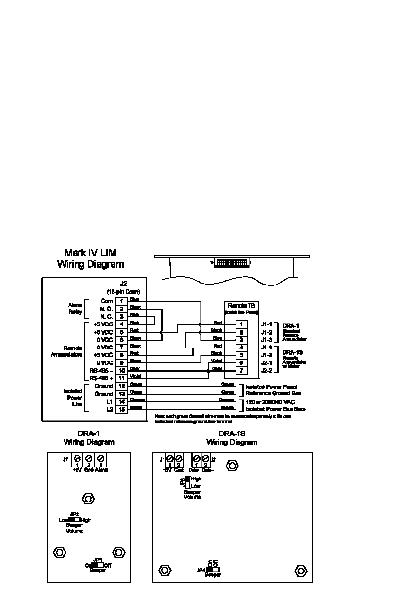
Up to 3 DRA-1S remotes are supported due to their higher power consumption. For
a single remote, this model should be connected with minimum 18 ga. wire for
wire lengths up to 50’, 16 ga. up to 75’, 14 ga. up to 100’ or 12 ga up to 125’. For
greater wiring distances, more than 3 simultaneously-operating remotes, or multiple
remotes sharing a single wire run, an auxiliary power supply is available. Consult the
factory for engineering assistance and pricing. With one or more of these supplies,
both the number of remotes and their distance from the LIM can be increased.
The LIM mounts using 4 holes in the corners of its front panel. In case of retrots
into existing panels, any additional brackets and harnesses needed are usually sup-
plied when a “retrot kit” is ordered from PG LifeLink for a specic application. Con-
sult the factory for assistance.
3.Operation
On initial power-up, the LIM goes through a self-test procedure. It rst displays its
rmware version as “P” followed by the version number, then performs a lamp test,
lighting all indicators and activating the audible alarm. Any remotes attached to the
LIM will perform the same self-test. It then enters automatic self-calibration.
Upon successful completion of this sequence (about 45 seconds), the LIM will begin
to indicate the THC of the isolated power system and attached equipment. Both the
digital and the analog bar-graph displays will show the predicted hazard current. If
the hazard current value is below the unit’s user-selectable alarm level setting of
2mA or 5mA, the green “Safe” indicator will be lit. If the hazard current goes above
the alarm set-point, the red “Hazard” light will light, and the audible alarm will
sound if enabled. To silence the alarm, press the “Silence” button on the front panel
of the LIM. The yellow “Silenced” indicator will light, and the red “Hazard” light will
remain lit. When the hazard current decreases below the alarm threshold, the Haz-
ard (and Silenced if active) lights will extinguish, and the green “Safe” light will come
back on, without any user action.
DRA-1 remotes silence only themselves and are not silenced if the LIM is silenced.
DRA-1S remotes and the LIM are all silenced together when any one is silenced.
The Mark IV performs automatic self-test and calibration every 24 hours. It also can
be manually tested at any time using the “Test” button on its front panel or on a
DRA-1S remote. Briey pressing and releasing the button will initiate self-calibration.
Press and hold the “Test” button to perform a functional test of alarm operation and
threshold such as the annual test required by NFPA 99. After holding for a few sec-
onds, the hazard current indication will begin to rise, and will reach the alarm trip
point within about 10 seconds. The LIM will simulate its operation during a hazard
condition by indicating a high hazard current value, lighting the “hazard” light, and
sounding the audible alarm, on the LIM displays and on any connected remotes.
4.User Settings
The Mark IV has a bank of DIP switches for user conguration, located at
the upper left of the Display board. Remove front cover to expose them.
S1 – Beeper volume: off = low, on = high (default is on, high vol)
S2 – Beeper Silence: off = active, on = silent (default is off, active)
S3 – THC range: off = 2 mA, on = 5 mA (default is on, 5 mA)
S4 – Factory use only: on = normal operate (default is on, operate)
S5, 6, 7, 8 – inactive: usually left in on position

PG LIFELINK Mark IV Line Isolation Monitor Instruction Manual
Page 6 of 7 Rev 1.3
5.Problem Solving
Parts of the following troubleshooting procedures may expose the technician to
electrical hazards. Troubleshooting should be performed only by qualied
personnel. Death or personal injury, or equipment damage, can result from
improper service procedures. Disconnect or turn off all power to the isolated power
panel and the LIM before handling any electrical connections. Use extreme caution
while power is applied and any live electrical parts are exposed.
To help expedite problem resolution, please perform all applicable tests as described
in this section before contacting PG LifeLink Technical Support, and be prepared to
report on the results.
During Normal Operation
LIM indicates high hazard current and alarm sounds
If this occurs during a procedure, it does not mean that there is necessarily
danger to patients or providers. Complete the procedure, move the patient to a
safe area, take the room or faulty equipment out of service, and follow hospital
reporting procedures to summon the appropriate technical personnel.
There is a fault in connected equipment. To locate the fault, rst unplug the most
recently plugged-in piece of equipment. Inspect cords, receptacles, and other
exposed electrical parts for contamination or damage.
Turn off all the branch circuit breakers in the isolated power panel, and verify that
the LIM returns to the “Safe” condition. Turn the breakers back on one at a time. A
circuit which causes the LIM indication to increases signicantly when turned on
has a problem. Inspect all wiring, devices, and connected equipment on that
circuit to isolate the fault(s).
Equipment incompatible with isolated systems (non-medical-grade) is connected.
The only solution to this cause of high THC that maintains the LIM’s protective
features is replacement of the offending equipment with medical grade.
LIM displays “CAL” (Calibrate)
This is a normal occurrence, every 24 hours during operation. The LIM will return
to operation within about 30 seconds.
At Installation
LIM indicates high hazard current and alarm sounds
There is a fault in connected equipment, faulty wiring, or too much wiring
connected to the isolated power system. Measure the voltage from each side of
the line to ground: if one side reads very low voltage, the problem is on that line.
The LIM is powered from a grounded (non-isolated) power source. Connect only
to isolated power.
Poor-quality incoming power with excessive harmonics or noise can cause both
high THC and erroneous LIM readings. Equipment with high-power rectiers or
switching elements such as battery chargers and motor speed controls,
connected to the same source as the isolated power panel, may cause this
symptom. If possible, feed the isolated power system from an alternate power
source; or attempt to locate and remedy the cause at the source.
If the LIM THC indication remains high with all breakers turned off, the isolated
power panel or the LIM itself may be malfunctioning or damaged. If another
known-good LIM of the same voltage rating is available, try substituting it into the
panel; or if a known-good panel of the same voltage rating is available, try
substituting the LIM into that panel. If the problem moves with the LIM, suspect

PG LIFELINK Mark IV Line Isolation Monitor Instruction Manual
Rev 1.3 Page 7 of 7
the LIM; otherwise, the LIM is not the cause. Or, if a suitable insulation tester is
available, the panel and wiring can be directly tested for faults.
LIM displays “Gnd” (Ground loss)
One of the two ground wires, at pins 12 & 13 of the connector, is disconnected.
Check all wiring carefully. Verify its integrity by measuring the resistance from pin
12 to pin 13 of the connector with it disconnected from the LIM . It should be
very low, less than 1 ohm.
A wire to a remote is shorted to earth ground. After startup this condition triggers
the loss-of-ground detection circuit. Disconnect all wires from the remote terminal
board, and power-cycle the LIM. If the alarm is cleared, inspect remote wiring
carefully and repair before re-connecting.
The ground detection circuit has been damaged by previous improper
connection (not covered by warranty).
LIM displays “Err” (Error)
The 3rd decimal point is lit (“Err.”):
A remote wire is shorted to earth ground. During startup, this condition
disables all measuring circuitry. See “Gnd” item (b) above.
Contamination of the contacts of a certain small mechanical relay. Sometimes,
especially during storage, a very thin layer of moisture or oxidation may build
up on these, preventing them from making good contact. The extra contact
resistance causes the calibration and self-test to fail. However, exercising them
mechanically may restore them. Power the unit down and back up, or
command auto calibration with the Test button, several times, waiting for the
unit to cycle completely each time. If it then successfully completes its self-test
sequence a few times, then this was probably the cause, and it can be placed
in service with condence in continued reliable operation.
One of the rst 2 decimal points is illuminated (“E.rr” or Er.r”): the LIM has
detected an internal malfunction. Make a note of which one.
LIM indication is very low or near zero regardless of external conditions
Both ground wires are disconnected from ground but are properly connected to
each other. See “Gnd” item (a) above. Trace all ground wiring and verify that it is
properly connected. If there is more than one ground bus in the panel, verify that
the one the LIM is connected to, is in fact grounded, and is not an “isolated
ground”. Avoiding this condition is the reason for connecting each LIM ground
wire individually to the reference ground bus.
LIM displays do not illuminate
Verify that the correct line voltage is applied at pins 14 & 15 of the LIM connector.
Disconnect all remotes from the isolated power panel at the terminal board.
6.Maintenance and Service
The Mark IV LIM contains no user-serviceable parts. If it requires internal service,
contact PG LifeLink Technical Support (see back cover) for a Returned Materials
Authorization. No returns will be accepted without a RMA.
NFPA 99 requires annual testing of Line Isolation Monitors of this type. Contact the
PG LifeLink Service Department for more information. Local codes or hospital policy
may require shorter test intervals and/or more exhaustive periodic testing.

PG LIFELINK
167 Gap Way
Erlanger, KY 41018
859-283-5900
800-287-4123
Notes (wire color codes, etc.)
Table of contents