IBA MBox User manual

ibaMBox
Mobile measuring system
Manual
Issue 1.3

Manufacturer
iba AG
Koenigswarterstr. 44
90762 Fuerth
Germany
Contacts
Head office +49 911 97282-0
Fax +49 911 97282-33
Support +49 911 97282-14
Web: www.iba-ag.com
This manual must not be circulated or copied, or its contents utilized and disseminated, without
our express written permission. Any breach or infringement of this provision will result in liability
for damages.
© iba AG 2017, all rights reserved.
The content of this publication has been checked for compliance with the described hardware
and software. Nevertheless, deviations cannot be excluded completely so that the full compli-
ance is not guaranteed. However, the information in this publication is updated regularly. Re-
quired corrections are contained in the following regulations or can be downloaded on the Inter-
net.
The current version is available for download on our website, www.iba-ag.com.
Windows®is a label and registered trademark of the Microsoft Corporation. Other product and
company names mentioned in this manual can be labels or registered trademarks of the corre-
sponding owners.
Realtek is a trademark of Realtek Semiconductor Corporation. This product is covered by one
or more of the following patents: US6,570,884, US6,115,776, and US6,327,625.
Certification
The product is certified according to European standards and directives. This product meets the
general health and safety requirements.
Further international customary standards and directives have been observed.
Note: This equipment has been tested and found to comply with the limits for a Class A digital
device, pursuant to part 15 of the FCC Rules. These limits are designed to provide reasonable
protection against harmful interference when the equipment is operated in a commercial environ-
ment. This equipment generates, uses, and can radiate radio frequency energy and, if not in-
stalled and used in accordance with the instruction manual, may cause harmful interference to
radio communications. Operation of this equipment in a residential area is likely to cause harmful
interference, in which case the user will be required to correct the interference at his own expense.
Issue
Date
Revision
Chapter
Author
Version
HW / FW
1.3
05/22/2017
Scope of delivery
3
st

ibaMBox
Manual
Issue 1.3
3
Contents
1About this manual...........................................................................................4
1.1 Target group ..................................................................................................4
1.2 Notations.......................................................................................................4
1.3 Symbols used................................................................................................5
2Introduction.....................................................................................................6
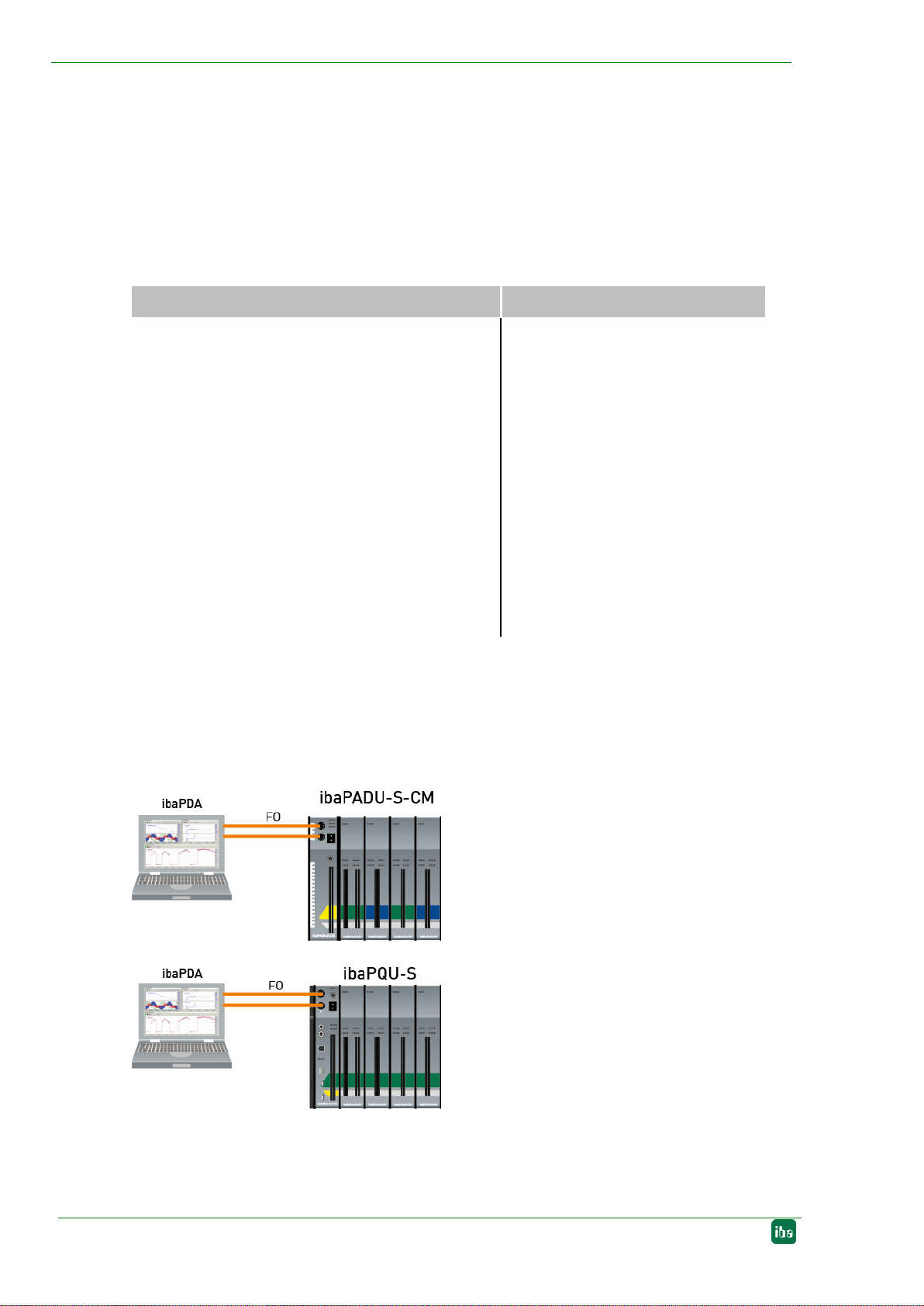
2.1 Connections...................................................................................................9
3Scope of delivery ..........................................................................................10
4Safety instructions........................................................................................ 11
4.1 Proper use...................................................................................................11
4.2 Special safety instructions ...........................................................................11
5System requirements....................................................................................12
5.1 External data acquisition..............................................................................12
5.2 Internal data acquisition...............................................................................12
6Assembly, connection, disassembly...........................................................13
6.1 Connection ..................................................................................................13
6.2 Start-up........................................................................................................13
6.3 Disassembly................................................................................................13
7Device description........................................................................................14
7.1 Device image...............................................................................................14
7.2 Connector panels.........................................................................................14
7.2.1 Central units ................................................................................................14
7.2.2 I/O modules.................................................................................................16
7.3 Interfaces and displays................................................................................19
7.3.1 Voltage supply.............................................................................................19
7.3.2 Electrical socket...........................................................................................19
7.3.3 Interfaces of the built-in central unit.............................................................19
7.3.4 FO connections X10 (TX) and X11 (RX) ......................................................19
7.3.5 Cable entry..................................................................................................20
7.3.6 Indicator elements .......................................................................................20
8Exchange built-in modules ..........................................................................21
9Order information..........................................................................................31
10 Technical data ...............................................................................................33
11 Support and contact.....................................................................................35

Manual
ibaMBox
4
Issue 1.3
1 About this manual
This manual describes the construction, the use and the operation of the device,
ibaMBox. You can find a general description of the iba modular system and further infor-
mation about the design of the modules and how to use and operate them in separate
manuals.
1.1 Target group
This manual is particularly intended for qualified professionals who are familiar with han-
dling electrical andelectronic modules aswell as communication andmeasurement tech-
nology. Aperson is regarded as professional if he/she is capable of assessing safety and
recognizing possible consequences and risks on the basis of his/her specialist training,
knowledge and experience and knowledge of the standard regulations.
1.2 Notations
The following designations are used in this manual:
Action
Notations
Command menu
Logic diagram menu
Call of menu command
Step 1 –Step 2 –Step 3 –Step x
Example:
Select Logic diagram –Add –New logic dia-
gram menu
Keys
<Key name>
Example: <Alt>; <F1>
Press keys simultaneously
<Key name> + <Key name>
Example:
<Alt> + <Ctrl>
Buttons
<Button name>
Example:
<OK>; <Cancel>
File names, paths
'File name', 'Path'
Example:
“Test.doc“

ibaMBox
Manual
Issue 1.3
5
1.3 Symbols used
If safety instructions or other notes are used in this manual, they mean as follows:
The non-observance of this safety information may result in imminent risk of death or
severe injury:
by an electric shock;
due to the improper handling of software products which are coupled to
input and output procedures with control function.
The non-observance of this safety information may result in potential risk of death or
severe injury.
The non-observance of this safety information may result in potential risk of injury or
material damage.
Note
A note specifies special requirements or actions to be observed.
Important note
Note if some special features must be observed, for example exceptions from the rule.
Tip
Tip or example as a helpful note or insider tip to make the work a little bit easier.
Other documentation
Reference to additional documentation or further reading.

Manual
ibaMBox
6
Issue 1.3
2 Introduction
The ibaMBox mobile measuring system is based on the iba modular system, which is
integrated in a compact and sturdy aluminum case. The same modules are used in
ibaMBox as are in the iba modular system; the backplane has been newly designed for
ibaMBox. In ibaMBox, a central unit can be combined with up to 4 I/O modules; the
central units and I/O modules available for ibaMBox are listed in the table below. The
communication and power supply of the modules is provided via a backplane bus built
into the case. ibaMBox is supplied pre-configured.
Central units
I/O modules
- ibaPADU-S-CM
(for modular data acquisition system)
- ibaPQU-S
(for power quality monitoring applications)
-ibaCMU-S
(for condition monitoring applications)
-ibaDAQ-S
(for stand-alone data acquisition)
ibaMS3xAI-1A
ibaMS3xAI-5A
ibaMS3xAI-1A/100A
ibaMS4xAI-380VAC
ibaMS8xAI-110VAC
ibaMS16xAI-10V (-HI)
ibaMS16xAI-24V (-HI)
ibaMS16xAI-20mA
ibaMS16xDI-220V
ibaMS16xDI-24V
ibaMS32xDI-24V
ibaMS8xICP
ibaMS8xIEPE
ibaMS4xUCO
Data acquisition
With the central units, ibaPADU-S-CM or ibaPQU-S, ibaPDA is required as an external
data acquisition system, which runs, for example, on a notebook. The notebook is con-
nected to the central unit via an ibaFOB-io-ExpressCard and a bidirectional fiber optic
connection.
Figure 1: Data acquisition with ibaPDA and notebook

ibaMBox
Manual
Issue 1.3
7
With the ibaCMU-S central unit, the ibaCMC condition monitoring center is required for
configuration and visualization.The measurementwith ibaCMU-S can run autonomously
without ibaCMC.
Figure 2: Stand-alone data acquisition with ibaCMU-S, configuration with ibaCMC
The ibaDAQ-S central unit is equipped with an integrated ibaPDA system and can cap-
ture and record data as astand-alone device. For configuration and operation, a monitor,
keyboard and mouse are required, or the configuration can be done via an ibaPDAclient
that has access to the device over the network.
Figure 3: Stand-alone data acquisition with ibaDAQ-S, configuration optional with ibaPDA
client
Other documentation
The handling and configuration of central units, I/O modules and ibaCMC are described
in the relevant device manuals. You can find the device manuals on the iba Software &
Manuals DVD supplied.
ibaMBox at a glance
Based on the reliable iba modular system
Central unit with up to 4 freely configurable input modules
Clearly arranged connections on connector panel
Practice-oriented connection technology (BNC, banana or Phoenix connectors)
Compact, sturdy aluminum case in a modern design
Suitable for industrial use in harsh environments
Ideally suited for start-up, troubleshooting, service and maintenance
CE approved

Manual
ibaMBox
8
Issue 1.3
Fields of application
The capture of analog input signals in the fields of:
measurement data acquisition
power generation and distribution
test benches
condition monitoring

ibaMBox
Manual
Issue 1.3
9
2.1 Connections
All connections and interfaces of the built-in modules are clearly connected and labeled
on a connector panel. The connections are designed as BNC, banana or Phoenix con-
nectors depending on the I/O module. The different module types are marked using the
same color code as in the classic iba modular system. The assignment of connections
to the individual modules can therefore be seen clearly.
Connectivity of the modules
Central unit
Inputs/outputs
Banana
(contacts)
BNC
connectors
Number of Phoe-
nix connectors
(pins)
ibaPADU-S-CM
8 digital inputs
-
-
1 (16) + 1(2)
ibaPQU-S
8 digital inputs
-
-
1 (16) + 1(2)
ibaCMU-S
8 digital inputs
-
-
1 (16) + 1(2)
ibaDAQ-S
2 digital inputs,
2 digital outputs
-
-
2 (4) + 1(2)
Module
Inputs/outputs
Banana
(contacts)
BNC
connectors
Number of Phoe-
nix connectors
(pins)
ibaMS3xAI-1A
3 analog inputs, 1 A AC
3x2
-
-
ibaMS3xAI-5A
3 analog inputs, 5 A AC
3x2
-
-
ibaMS3xAI-1A/100A
3 analog inputs,
1 A AC/100 A DC
3x2
-
-
ibaMS4xAI-380VAC
4 analog inputs, 380 V AC
4x2
-
-
ibaMS8xAI-110VAC
8 analog inputs, 110 V AC
8x2
-
-
ibaMS16xAI-10V
16 analog inputs, ±10 V
16x2
16
2 (16)
ibaMS16xAI-10V-HI
16 analog inputs, ±10 V
(high impedance)
16x2
16
2 (16)
ibaMS16xAI-24V
16 analog inputs, ±24 V
16x2
16
2 (16)
ibaMS16xAI-24V-HI
16 analog inputs, ±24 V
(high impedance)
16x2
16
2 (16)
ibaMS16xAI-20mA
16 analog inputs, ±20 mA
16x2
16
2 (16)
ibaMS16xDI-220V
16 digital inputs, ±220 V
-
-
2 (16)
ibaMS16xDI-24V
16 digital inputs, ±24 V
16x2
-
2 (16)
ibaMS32xDI-24V
32 digital inputs, ±24 V
-
-
4 (12)
ibaMS8xICP
8 inputs for ICP/IEPE vibration
sensors
-
8
2 (12)
ibaMS8xIEPE
8 inputs for ICP/IEPE vibration
sensors
-
8
2 (12)
ibaMS4xUCO
Counter module, 4 inputs
-
-
1 (6) + 1 (16) +
2(18)

Manual
ibaMBox
10
Issue 1.3
3 Scope of delivery
After unpacking the delivery, please check everything is there and that none of the parts
are damaged.
The scope of delivery comprises:
ibaMBox with built-in central unit, I/O modules and connector panels, according to
order
Power cord
Covering caps for FO cables and USB
Manual ibaMBox
Manuals central unit and I/O modules, according to customer’s equipment
Plug components for Phoenix connectors, according to customer’s equipment
iba Software & Manuals DVD

ibaMBox
Manual
Issue 1.3
11
4 Safety instructions
4.1 Proper use
The device is an electrical apparatus. It may only be used for the following applications:
Measurement data acquisition and analysis
Applications of the software products (such as ibaPDA) and hardware products of
iba AG.
The device is only to be used as shown in chapter 'Technical Data.'
4.2 Special safety instructions
Be sure to follow the safety instructions of each module in the relevant manuals. The
following notes also apply for ibaMBox.
Observe the operating voltage range.
Only connect the device to a supply voltage corresponding to the specifications on the
built-in power supply.
Never use the device with a damaged power cord.
The device is approved for the CAT II measurement category.
The device must not be connected to CAT III or CAT IV categories.
Important note
Do not open the coverage, the connector panels or the built-in modules. Opening any
of them leads to a loss of warranty!
Repairs must only be carried out by the manufacturer.
Note
Clean the case only on the outside with a dry or slightly damp and statically dis-
charged cloth.

Manual
ibaMBox
12
Issue 1.3
5 System requirements
5.1 External data acquisition
When using the ibaPADU-S-CM or ibaPQU-S central units, an external notebook (or PC)
with ibaPDAis required for data acquisition.
AC 100 / 240 V (±10%) power supply
Notebook with the following minimal requirements:
2 GHz Core2Duo or better
At least 2 GB RAM
At least 10 GB of free space on the hard disk for measurement values
ExpressCard slot
You can find suitable notebooks on our homepage, http://www.iba-ag.com.
ibaFOB-io-ExpressCard
An ibaNet fiber optic patch cable (duplex) for connecting the central unit and note-
book
ibaPDA from version 6.36.0
5.2 Internal data acquisition
The ibaDAQ-S central unit enables data acquisition and storage on the device. External
input devices are required for operation and configuration.Alternatively the configuration
can be done using an ibaPDA client that has access to ibaDAQ-S over the network.
AC 100 / 240 V (±10%) power supply
Optional
External input devices for operation: monitor, keyboard and mouse
ibaNet fiber optic patch cable (duplex) for connecting additional iba devices
With the ibaCMU-S central unit, the data is also stored on the device. However, the
ibaCMC condition monitoring center, which is connected via the network, is required for
configuration and visualization.
AC 100 / 240 V (±10%) power supply
ibaCMC Condition Monitoring Center (only for configuration)
Network connection to ibaCMC

ibaMBox
Manual
Issue 1.3
13
6 Assembly, connection, disassembly
6.1 Connection
1. Disconnect ibaMBox from the power supply.
2. Connect all measuring cables.
3. If you are using an external notebook, connect the central unit to the notebook via an
ibaNet fiber optic patch cable (duplex):
the RX input (X11) of the central unit with the TX interface of the ibaFOB-io-Ex-
pressCard in the notebook,
the TX output (X10) of the central unit with the RX interface of the ibaFOB-io-Ex-
pressCard in the notebook.
4. If you have connected all the necessary cables, switch the voltage supply on at the
on/off switch.
6.2 Start-up
Refer to the information on setup and configuration with ibaPDA(or ibaCMC) in the man-
ual of your central unit.
6.3 Disassembly
1. Disconnect ibaMBox from the power supply.
2. Remove all cables.

Manual
ibaMBox
14
Issue 1.3
7 Device description
7.1 Device image
Figure 4: Open ibaMBox
1 Cable entry
2 Connector panels (depending on the order)
3 Voltage supply
4 Electrical socket
5 Interfaces of the built-in central unit
6 FO output (TX) X10
7 FO input (RX) X11
8 Operating status display of the central unit L1... L4
9 Fan
7.2 Connector panels
Depending on the modules built in, the connector panels are optionally available with
BNC, banana or Phoenix connectors.
The following figures show each type of connector panel as an example. The number of
connectors depends on the modules actually built in.
7.2.1 Central units
The connector panels of the central units are only available with Phoenix connectors. In
addition to the digital inputs and outputs, a 2-pin Phoenix connector is used for the power
supply for other iba devices (power out: 24 V, max. 20 W).
The connectors of the ibaPADU-S-CM, ibaCMU-S and ibaPQU-S central units are the
same.

ibaMBox
Manual
Issue 1.3
15
Example: ibaPADU-S-CM central unit
Connections:
8 digital inputs:
16-pin connector
Power out:
2-pin connector
24 V, max. 20 W
Ensure the correct polarity when connec-
ting the power supply.
Figure 5: ibaPADU-S-CM connector panel
ibaDAQ-S central unit
Connections:
2 digital inputs DI:
4-pin connector
2 digital outputs DO:
4-pin connector
Power out:
2-pin connector
24 V, max. 20 W
Ensure the correct polarity when connec-
ting the power supply.
Figure 6: ibaDAQ-S connector panel

Manual
ibaMBox
16
Issue 1.3
7.2.2 I/O modules
Phoenix connector model
Example: ibaMS16xAI-10V
Figure 7: ibaMS16xAI-10V connector panel with Phoenix connector
Connection technology of the I/O modules with Phoenix connectors:
I/O modules
Connection technology
ibaMS16xAI-10V (-HI)
ibaMS16xAI-24V (-HI)
ibaMS16xAI-20mA
ibaMS16xDI-220V
ibaMS16xDI-24V
2 x 16-pin connector
ibaMS32xDI-24V
4 x 12-pin connector
ibaMS8xICP
ibaMS8xIEPE
2 x 12-pin connector
Note
Detailed type designation and part numbers of the built-in Phoenix base strips and infor-
mation about the corresponding Phoenix plug components can be found in chapter 9.

ibaMBox
Manual
Issue 1.3
17
ibaMS4xUCO
Connections:
8 digital inputs DI:
16-pin connector
4 digital outputs DO:
6-pin connector
Counter inputs:
37 pin D-Sub connector
Figure 8: ibaMS4xUCO connector panel
Banana connector model
Analog input modules and the digital input module ibaMS16xDI-24V are available with
banana connectors. Each input has 2 contacts (+,-).
Example: ibaMS16xAI-10V
Figure 9: ibaMS16xAI-10V connector panel with banana connector

Manual
ibaMBox
18
Issue 1.3
BNC connector model
A BNC connector is available for each input.
BNC connector assignment:
Example: ibaMS16xAI-10V
Figure 10: ibaMS16xAI-10V connector panel with BNC connectors
Example: ibaMS8xIEPE
Figure 11: ibaMS8xIEPE connector panel with BNC connectors and LED display

ibaMBox
Manual
Issue 1.3
19
Each input of modules ibaMS8xIEPE and ibaMS8xICP with BNC connector is equipped
with an LED. The LEDs indicate the following states of the measured signal:
LED per channel
Meaning
Green
3 V … 20 V
within measurement range
Red
Wire not connected or broken
7.3 Interfaces and displays
7.3.1 Voltage supply
Power supply feedAC 100/240 V with panel plug for non-heating appliances and switch.
Maximum power consumption 3.0A (100 V) / 1.5 A (240 V)
Built-in microfuse: 1.6 A / 250 VAC, time-lag
7.3.2 Electrical socket
Built-in socket for the power supply of external devices, such as a notebook.
Power out: max. 250 W
7.3.3 Interfaces of the built-in central unit
The interfaces available here vary depending on the built-in central unit. Please see the
corresponding device manual.
7.3.4 FO connections X10 (TX) and X11 (RX)
X11 (RX): FO receive interface
X10 (TX): FO send interface
Function in the central units, ibaPADU-S-CM, ibaPQU-S, ibaCMU-S (optional)
Measurement and configuration data are exchanged with the external ibaPDA system
(e.g. notebook) through fiber optic connections. An ibaFOB-io-ExpressCard is needed in
the notebook in order to receive and send data.
Function in the ibaDAQ-S central unit
The FO connections function as an ibaFOB-io card. Other iba devices can be connected
via it, such as the ibaPADU family, iba bus monitors and system connections.
The FO connections are designed for cables with 62.5/125 μm multimode fibers with ST
connectors. Suitable FO patch cables are available from iba.
Supported ibaNet protocols of the central units:
32Mbit Flex
32Mbit
5Mbit
3Mbit
ibaPADU-S-CM
-
-
-
ibaCMU-S
-
-
ibaPQU-S
-
-
-
ibaDAQ-S

Manual
ibaMBox
20
Issue 1.3
7.3.5 Cable entry
The cables can be led out through openings on both sides of the case. The openings are
protected against dust by brushes.
7.3.6 Indicator elements
The light-emitting diodes (LED) of the central unit are visible and show the operating
status of the central unit.
LED
Status
Description
L1
Red
Off
Out of operation, no supply voltage
Hardware failure, controller is off
L1
Green
Blinking slowly
Ready for operation
Irregular blinking indicates an overload or device startup.
The startup process can take up to 90 s.
Blinking quickly
System programming mode
Firmware update active
On
Controller in overload
L2
Yellow
Off
No backplane bus access
On
Backplane bus access on I/O modules
L3
White
Off
No FO signal detected
Blinking
Fiber optic signal detected, configuration error, the recei-
ved ibaNet protocol is not compatible with the one confi-
gured in the device
On
FO signal detected
L4
Red
Off
No error
Blinking
Disturbance, internal device applications are not running.
On
Hardware error
Important note
If the LED L4 indicates a failure, please contact iba Support.
Table of contents
Other IBA Measuring Instrument manuals
Popular Measuring Instrument manuals by other brands

Rion
Rion TL735G Technical manual

Cameron
Cameron Scanner 3100 EFM Hardware manual

Shanghai Sunny Hengping Scientific Instrument Co., Ltd
Shanghai Sunny Hengping Scientific Instrument Co., Ltd UV2000 instruction manual

TESTO
TESTO 312 instruction manual

promethean
promethean ACTIVslate XR TP-1471-UK quick start guide

Rion
Rion HCA518T Technical manual

Boyo Vision
Boyo Vision VTM7012QFHD user manual

Ronde & Schwarz
Ronde & Schwarz R&S FPL1007-P6 user manual

HP
HP HP 5526A Operating Note and Program Listings

Pessl Instruments
Pessl Instruments mMETOS CLIMA user manual

Hantek
Hantek 1832C user manual

Viessmann
Viessmann Energy meter Installation and service instructions for contractors