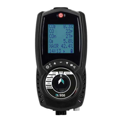
Kane KANE975 User manual

KANE975
Industrial Flue Gas Analyser
Stock No: MAN00002 Rev: 1.00520 May 2020
© Kane International Ltd

Page 2
CONTENTS
Page No:
KANE975 OVERVIEW 4
INSTRUMENT FEATURES AND KEYPAD 5
KEYPAD BUTTONS 6
INSTRUMENT LAYOUT 7-8
BATTERIES 9
BATTERY TYPE 9
REPLACING BATTIERES 9
TIME AND DATE 9
CHARGING NIMH BATTERIES 9
BATTERY DISPOSAL 10
GENERAL SAFETY 11
FIRST TIME USE 12
MENU LIST 12
GENERAL OPERATING PRINCIPLE 13
STATUS 13
STATUS PAGE 1 13
STATUS PAGE 2 13
STATUS PAGE 3 13
MENU SETTING AND SETUP 14
ANALYSER UNITS 15
ALARMS 15
SCREEN 16
REPORTS 16
TRENDS 17
TRENDS SETUP 17
SERVICE 18
MANUAL AIR ZERO 18
MANUAL PRS ZERO 18
USING THE ANALYSER 19
EVERY TIME YOU USE THE ANALYSER 19
AUTOMATIC CALIBRATION 19
MAIN DISPLAYS 20
LOGGING DATA 21
PRINTING DATA 21
SAMPLING THE FLUE GAS 22
TAKING A PRESSURE READING 23
TAKING A FLOW READING 23

Page 3
Page No:
REGULAR CHECKS DURING SAMPLING 23
NORMAL SHUTDOWN SEQUENCE 24
STANDARD PRINTOUT 25
SOFTWARE COMPATIBILITY 25
STORING AND RETRIEVING LOGS 26
STORING A LIVE TEST 26
VIEW STORED LOG 26
PRINTING A STORED LOG 27
DELETING STORED LOGS 27
SETTING THE AUTO LOG TIME 27
START AUTO LOG 28
START AUTO PRINTING 28
AVERAGED REPORTS. 29
MAINTENANCE 30
EMPTYING AND CLEANING THE INTEGRAL WATER TRAP 30
EMPTY THE WATER TRAP 30
CHANGING THE PARTICLE FILTER 30-31
NOX CALCULATION 31
PROBLEM SOLVING 31
KANE DASHBOARD 32-36
ONLINE BOOKING PROCEDURE 34-36
ANALYSER ANNUAL SERVICE AND RECIRTIFY 37
SERVICE CALIBRATE RECIRTIFY 37-39
RETURNING YOUR ANALYSER TO KANE 39
PACKING YOUR ANALYSER 39
WHEN WE RECEIVE YOUR ANALYSER 39
WHERE TO SEND YOUR ANALYSER 40
COLD WEATHER PRECAUTIONS 40
SPECIFICATIONS 41-42
EU DECLARATIONS OF CONFORMITY 43-44
PRODUCT REGISTRATION 45-46

Page 4
KANE975 OVERVIEW
The KANE975 incorporates the many years of experience KANE has
gathered in gas sensing technologies and packages it into an advanced
handheld industrial combustion analyser.
With the ability to fit up to 7 gas sensors, including KANE’s own
proprietary NDIR CO2 sensor for true CO2 measurement, all aspects of
the combustion process can be monitored.
In addition to the gas sensors the KANE975 also includes dual type K
thermocouple inputs and differential pressure measurement. It is fitted
with KANE wireless as standard for operation with the KANE Live
Android application, further enhancing the user experience. As with all
advanced KANE analysers, the KANE975 supports the KANE IR printer
as standard.
The full colour graphical display provides the user with clear information
and an intuitive user interface enables simple operation.
The KANE975 also includes an over-range protection system to prevent
the CO sensor from being poisoned by excessive levels of CO.
The KANE975 has been independently certified to EN50379 parts 1, 2 &
3 by TUV.
The KANE975 can be fitted with the following sensors:
•
CO
•
CO2
•
O2
•
NO
•
NO2
•
SO2
•
H2S

Page 5
INSTRUMENT FEATURES AND KEYPAD

Page 6
KEYPAD BUTTONS
Icon
Description
ON/OFF
PLAY/PAUSE
PRINT/F1
HOME
STORE/F2
UP
DOWN
BACK/CANCEL
OK/ENTER

Page 7
INSTRUMENT LAYOUT

Thermocouple
____
111
Stainless
Steel
Shaft
_
_.
,
1
Depth Stop Cone
_____
Hanging Hook
Page 8

Page 9
BATTERIES
BATTERY TYPE
This analyser has been designed for use with rechargeable Nickel
Metal Hydride (NiMH) batteries. No other battery types are
recommended and will void warranty.
WARNING
Do not try to charge the unit with Alkaline batteries fitted.
Do not mix NiMH cells of different capacities or from
different manufacturers, all cells must be identical.
REPLACING BATTERIES
Turn over the analyser, fit 6 NiMH “AA” rechargeable batteries
in the battery compartment. Take great care to ensure they
are fitted with the correct battery polarity. Replace the
battery cover.
TIME AND DATE
When changing batteries, the time and date will need setting.
CHARGING NIMH BATTERIES
The KANE975 employs an advanced power management
system to ensure optimal performance. When a low battery
event is detected the management software will warn the user
until the battery reaches a critical level of discharge, at this
point the unit will shut down.

Page 10
If the user attempts to turn on the analyser while the batteries
are discharged the power management system will prevent turn
on.
Under normal circumstances charging is simply a case of plugging
in the supplied 12V charger (CU12VDC2A1), the analyser will
automatically activate battery charging and indicate the progress
on the display.
In the event of the analyser detecting an extreme state of
discharge of the main batteries, the user will be required to
perform the following procedure:
1.
Plug in supplied 12V Charger
2.
Press and hold the “On” button for 5 seconds
This will allow the charging of extremely flatbatteries.
BATTERY DISPOSAL
Always dispose of depleted batteries using approved disposal methods
that protect the environment.

Page 11
GENERAL SAFETY
SAFETY WARNING
This analyser extracts combustion gases that may be toxic in relativity
low concentrations. These gases are exhausted from the bottom of the
analyser. This analyser must only be used in well-ventilated
locations by trained and competent persons after due consideration
of all the potential hazards.
Users of portable gas detectors are recommended to conduct a “bump”
check before relying on the unit to verify an atmosphere is free from
hazard.
A “bump” test is a means of verifying that an instrument is working within
acceptable limits by briefly exposing to a known gas mixture formulated
to change the output of all the sensors present. (This is different from a
calibration where the instrument is also exposed to a known gas mixture
but is allowed to settle to a steady figure and the reading adjusted to the
stated gas concentration of the test gas).
Protection Against Electric Shock (In accordance with EN 61010-1:
2010):
This analyser is designed as Class III equipment and should only be
connected to SELV circuits. The battery charger is designated as:
•
Class II equipment
•
Installation category II
•
Pollution degree 2
•
Indoor use only
•
Altitude to 2000m
•
Ambient temperature 0°C-40°C
•
Maximum relative humidity 80% for temperatures up to 31°C
decreasing linearly to 50%RH at 40°C
•
Mains supply fluctuations not to exceed 10% of the nominal voltage

Page 12
FIRST TIME USE
Charge the battery for 12 hours. Following this, an overnight charge
should be sufficient for an average 8-hour day.
Take time to read the manual fully, be aware that the analyser
configuration that you have purchased may not support all the
features detailed in this manual.
When using the analyser for the first time you will need to set it up to
your requirements.
MENU LIST
Press HOME to display MENU list.
MENU ITEM
COMMENTS
STATUS
Current instrument status, software version etc.
SETUP
Menu to change analyser settings.
ANALYSER UNITS
Change measurement parameters.
ALARM
Configure the alarms for the analyser.
SCREEN
Configure the display.
REPORTS
Configure logging parameters and view stored data.
TRENDS
Configure and display Trend information.
SERVICE
Reserved.
MANUAL AIR ZERO
Manually trigger a Air Zero purge.
MANUAL PRS ZERO
Manually trigger a zero calibration for the pressure sensor.
NOTE: At the bottom of the screen the current time, date and battery
status are displayed. Check time and date are correct, they can only be
changed if there are NO logs in Memory. This protects the integrity of
the logged data.

Page 13
GENERAL OPERATING PRINCIPLE
Use the UP/DOWN keys to move the cursor. Press OK to select a
line. This is the way all the menus work. Press HOME at any time to
get back.
STATUS
These pages list the current setup of the analyser
PAGE 1
PAGE 2
PAGE 3

Page 14
MENU SETTINGS
SETUP
MENU ITEM
OPTIONS/COMMENTS
LANGUAGE
Select: ENGLISH, FRENCH, GERMAN, DUTCH, ITALIAN,
SPANISH, FINNISH
MAIN PURGE
Main Purge Duration Time
Main Purge Interval Time
Auto Zero Cal
Over Range Protection
Select 90 to 300 seconds
Select 10 to 180 mins
Select Yes/No
Select, OFF or user selectable max value (up to
the overload value of the CO fitted sensor)
PRINTER
Select, Wireless (Android app), KANE IRP, KANE IRP2
SET TIME
NOTE: Can only be changed if all logs in
memory have been cleared. HH:MM:SS
format
E.g. 7am = 07:00:00, 7pm = 19:00:00
SET DATE
NOTE: Can only be changed if all logs in memory have
been cleared.
DD/MM/YY
UNIT ALARMS
Gas Alarm
Battery Alarm
Yes/No
Yes/No
Watertrap Alarm
Yes/No
WIRELESS PASS KEY
1111 (wait 5 seconds after entering last digit)

Page 15
ANALYSER UNITS
MENU ITEM
OPTIONS/COMMENTS
FUEL ORIGIN
Select desired option via UP/DOWN and OK to confirm
FUEL TYPE
Select desired option via UP/DOWN and OK to confirm
EFFICIENCY
Select Gross, Net or Condensing
GAS UNITS
Select desired option via UP/DOWN and OK to confirm
TEMPERATURE
Select desired option via UP/DOWN and OK to confirm
PRESSURE
NOTE: Select m/s for PITOT.
Select desired option via UP/DOWN and OK to confirm
SET PERCENTAGE
REFERENCE O2
Set the O2 Reference value
SET NOx CALCULATION
Select the calculation method and Reference value
CONVERSION FACTORS
Set the PITOT factor
ALARMS
MENU ITEM
OPTIONS/COMMENTS
CO ALARM
400 ppm (User selectable, OFF up to maximum
measurement range value)
NO ALARM
1000 ppm (User selectable, OFF up to maximum
measurement range value)
NO2 ALARM
1000 ppm (User selectable, OFF up to maximum
measurement range value)
NOx ALARM
1000 ppm (User selectable, OFF up to maximum
measurement range value)
SO2 ALARM
2000 ppm (User selectable, OFF up to maximum
measurement range value)
H2S ALARM
200 ppm (User selectable, OFF up to maximum
measurement range value)
ALARM TIME
120 to 600 seconds
NOTE: Each alarm can be set in increments of 25pmm.

Page 16
SCREEN
MENU ITEM
OPTIONS/COMMENTS
MODE
Choose font size
LINE 1-6
Choose displayed parameter
LINE 7-12
Choose displayed parameter
LINE 13-18
Choose displayed parameter
LINE 19-24
Choose displayed parameter
RESTORE USER LINES
DEFAULTS
Changing the font size, changes the appearance of
displayed pages. The larger the font size the more
pages are needed to display a particular function
REPORTS
MENU ITEM
OPTIONS/COMMENTS
VIEW REPORTS
Change LOG ON to view report
DELETE ALL REPORTS
Yes/No
AUTO LOG TIME
Set timer
START AUTO LOG
Switch on/off
START AUTO PRINTING
Switch on/off
AVERAGE REPORT
Set up average report
HEADER 1
Change header data
HEADER 2
Change header data
TRENDS
See Section 6.2.6

Page 17
TRENDS
MENU ITEM
OPTIONS/COMMENTS
REPORTS RANGE
Set lower and upper LOG range
TRENDS SETUP
See below
START TREND A
Switch to display screen
START TREND B
Switch to display screen
START TREND C
Switch to display screen
START TREND D
Switch to display screen
START DUAL TREND AB
Switch to display screen
START DUAL TREND CD
Switch to display screen
START QUAD TREND
Switch to display screen
TRENDS SETUP
MENU ITEM
OPTIONS/COMMENTS
SAMPLE PERIOD
TREND A
0.25 secs to 15 secs, select parameter, select line colour, set
x axis upper limit, set x axis lower limit
SAMPLE PERIOD
TREND B
0.25 secs to 15 secs, select parameter, select line colour, set
x axis upper set x axis lower limit
SAMPLE PERIOD
TREND C
0.25 secs to 15 secs, select parameter, select line colour, set
x axis upper set x axis lower limit
SAMPLE PERIOD
TREND D
0.25 secs to 15 secs, select parameter, select line colour, set
x axis upper set x axis lower limit
With the TRENDS graphs on the display you can use the DOWN key to
scroll a curser across the display (vertical red line) and pick out actual
readings.

Page 18
SERVICE
Restricted area.
MANUAL AIR ZERO
Use this function to reset toxic sensor to 0 ppm and the oxygen sensor to
20.95%.
It is recommended that sensors are purged in fresh (outside)
air for at least three minutes before zeroing. If the analyser is
zeroed with its probe still in the flue, erroneous reading may
result.
MANUAL PRS ZERO
Use this function to zero the pressure transducer.
It is recommended that all pressure hoses are disconnected from the
analyser before zeroing.

Page 19
USING THE ANALYSER
EVERY TIME YOU USE THE ANALYSER
BEFORE SWITCH-ON CHECK THAT:
•
The particle filter is dry and clean
•
The water trap and probe line are empty of water
•
All hoses connections, etc, are properly made
•
The probe is sampling CLEAN AMBIENT air
•
The water trap is correctly fitted and instrument upright
•
The flue temperature is connected
Switch ON the instrument by pressing
AUTOMATIC CALIBRATION
During this sequence the analyser pumps fresh air into the sensors to
allow toxic sensors (if fitted) to be set to zero and the oxygen sensor to
be set to 20.95%.
After switch-on the analyser will briefly display header information:-
Software version number and analyser serial number.
Then “ANALYSER PURGING 90 secs” countdown will appear on top of
the main screen.
The calibration time counts down in seconds to zero, calibration time
may be changed to 90, 120, 180, 300 seconds.
NOTE:- Three minutes is recommended to allow the sensors to stabilise
fully, anything less than this may result in drift of the toxic and oxygen
sensors in clean ambient air.

Page 20
MAIN DISPLAYS
NOTE! Check for correct date and time before starting to take readings.
Press the UP or DOWN key to get to the second display
Table of contents
Other Kane Measuring Instrument manuals
Popular Measuring Instrument manuals by other brands

MULTISPAN
MULTISPAN MFM 14DC-M1 manual

Deif
Deif ADL-111Q96/xxVDC Series Installation & operation instructions

GEM
GEM 566 operating instructions

DeWalt
DeWalt DW03050 instructions

Elenco Electronics
Elenco Electronics XK-550 instruction manual

Hanna Instruments
Hanna Instruments Checker HI707 instruction manual