PGO BR-150 Bug Rider User manual

BR-150
SERVICE MANUAL
Manufactured by PGO
of Motive Power Industry Co., Ltd

Content
Chapter 1 : Service notation
¢Specification
¢Locking torque
Chapter 2: Engine dismantle& inspection
¢Engine dismantle
¢Engine inspection
¢Transmission dismantle & inspection
¢Carburetor adjustment
Chapter 3 : Chassis inspection
¢Operation
¢Steering inspection & adjustment
¢Brake inspection & adjustment
¢Installation
Chapter 4 : Electric
¢Parts location
¢Charging inspection & adjustment
¢Ignition inspection
¢Wiring diagram

PREFACE
This manualoffers all service specialists with the technological
procedures of maintenance, repairing for BR-150 show those whom may
concern how to maintain in detail, repair, change parts, troubleshoot and
reassemble, etc.
At every important section we illustrate by assembly, explosion
diagrams and photographs, if necessary, please check the diagrams
already shown.
Though we have tried our best, please kindly instruct us any
faults found in this manual.
MOTIVE POWER INDUSTRY CO., LTD.

BUGXTER SPECIFICATION
Name FRAME STEEL
TYPE SUSPENSION SYSTEM
DIMENSION FRONT SINGLE A ARM
TOTAL LENGTH REAR SWING ARM
TOTAL WIDTH TRANSMISSION
TOTAL HEIGHT RPIMARY RATIO 1
WHEELBASE SECONDARY RATIO 40/16*42/13
DRY WEIGHT 263KG CLUTCH C.V.T.
FRONT TIRE
REAR FRONT
TOTAL REAR
LOAD 2 PERSONS(110KG) BRAKE SYSTEM
VEHICLT PERFORMANCE FRONT DISC BRAKE
TOP SPEED 70KM/H REAR DRUM BRAKE
FUEL CONSUMPTION 25KM/L LIGHT
CLIMBING ABILITY 25 HEAD
LIGHT(H/L) 12V-35W/35
W*2
TAIL LIGHT 12V-5W
CYCLE 4 BRAKING LIGHT 12V-21W
FUEL UNLEADED TURN LIGHT 12V-10W
CYLINDER NUMBER 1
ARRANGEMENT HORIZONTAL
DISPLACEMENT 150.1 cc
BORE 57.5 mm
STROKE 57.8 mm
COMPRESSION RATIO 9.4 : 1
MAX. POWER/RPM 7.5kw/7750rpm
AMX. TORQUE/RPM 10.2N-M/6500rpm
IDLE RPM 1700 100 RPM
IGNITION CDI
SPARK PLUG NGK CR7HSA
COOLING FORCE AIR & OIL
STARTER ELECTRIC
FUEL MIXING OIL PUMP
LUBRICATION SEPARATED

1.1 The operation notice:
1.Always replace gasket, O ring, cotter, pins and clip whenever reassembled.
2.When tighten screws ornuts, lock tightly as per specified locking torque, and in the sequence
of
cross direction.
3.Use PGO,or PGO Recommended parts.
4.After dismantling please wash all parts necessary for checking and grease all
contact surfacewhen reassembling.
5.Usegrease recommended by P.G.O.
6.When removing battery, please dismantle the negative pole(-) first, when
assemblingplease connect positive pole (+) first.
6.Before installing a new fuse, confirmthe specification is correct or not.
7.After reassembling, please re-check that all connecting point, locking parts,
circuits, polarcharacteristics are good, before selling out.

1.2 TORQUE VALUE
1. Engine:
NO Locking location Q’TY Thread dia. (mm) Lockingtorque (kg-m) Remark
1 Cylinder head bolt A (intake ) 2 6 0.9~1.1
2 Cylinderhead bolt B (Exhaust) 2 8 2.2
3 Cap,oil filter graze 1 30 1.5~2.0
4 Flange nut, cam shaft base 4 8 2.2
5 Fixing nut, air valve adjustment 2 5 0.7
Greasing on thread
6 Guiding pinbolt, inner chain adjustment 1 6 0.9~1.1
7 Oil bolt 1 8 1.7~2.0
8 Fixing nut, clutch outer 1 12 5.0~6.0
9 Nut, driven plate 1 12 5.0~6.0
10 Nut, driving plate 1 12 5.0~6.0
11 Spark plug 1 10 1.2~1.3
12 Nut, driveclutch 1 22 9.0~10.0 Left thread
13 Screw, inner chain adjuster 1 6 0.4~0.6
2.General parts please refer the following table:
NO Item Torque (kgf-m)
1 5mm bolt and nut 0.45-0.6
2 6mm bolt and nut 0.8-1.2
3 8mm bolt and nut 1.8-2.5
4 10mm bolt and nut 3.4-4.0
5 12mm bolt and nut 5.0-6.0
6 5mm screw 0.35-0.5
7 6mm screw 0.7-1.1
8 6mm flangebolt and screw 1.0-1.4
9 7mm flangebolt and screw 1.0-1.4
10 8mm flangebolt and screw 2.0-3.0
11 10mm flange bolt and screw 3.0-4.0

3.Locking Torque Standard (Chassis)
No Locking location Qty Thread dia
(mm) Kg-m Remark
1 Wheel nut 16 10 6.0
2 Wheel axle nut 1 16 8.0
3 Front absorber bolt 4 10 6.0
4 Lower suspension arm bolt 2 10 6.0
5 Steering handle bolt 6 3 0.5
6 Seat belt fixture 5 8 3.0
7 Upper suspension arm 2 8 3.0
8 Tie rod nut 4 10 5.0
9 Roll cage bar 6 8 4.0
10 Rear swing arm, lower 2 12 6.0
11 Engine hanger with frame 2 10 3.5~4.5
12 Engine hanger with engine 1 10 3.5~4.5
13 Rear absorber 4 10 3.5~4.5
14 Connecting rod 4 8 3.0
15 Chain adjusting bolt, upper 1 12 6.0
16 Chain adjusting bolt, lower 1 12 6.0
17 Brake caliper fixture 6 8 2.5~3.0
18 Brake hose bolt 6 8 2.5~3.0
19 Reverse gear shaft 1 16 11.0
20 Rear sprocket 4 8 3.0
21 Brake disk 8 8 3.0

1.3 In order to achieve safe riding, good performance and reduce pollution, please execute the
following
recommended maintenance table base upon average driving condition. Driving in unusual dusty
areas, require more frequent servicing. MONTHS/DISTANCE(IN KM)FOR CHECKING
Item Checking Content 1 or
300 km 3 or
3000k 6 or
5000k 9 or
8000k 12 or
10000k 15 or
13000k 18 or
15000k
Engineoil * Replace (800cc, total 900cc) R Replace it per 1,000km
Oil Filter * Replace R Replace it per 5,000km
Coarseoil filter* (on oil
draining bolt) Clean orreplace it if necessary C Cleanit per 3,000km or replace it if required
Oil cooler Clean orreplace it if necessary I C C C
Air filter* Replace it if required Replace it per 1,000km
Gearoil * Replace (90cc, total 110 cc) R R R R
Brake performance Leakingand function check I I I I I I I
Brake oil,disk, pad,
hose, mastercylinder Leaking and worn -out check or
replace it ifnecessary IIIIIII
Clutch linings * Check or replace it if necessary I I I I I I
Tires Worn-out check orreplace it if
necessary I I I I I I
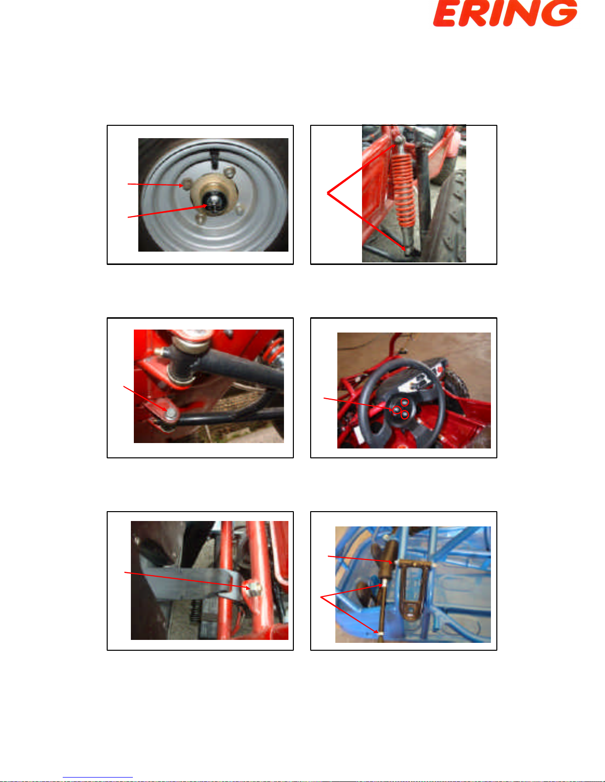
Wheel bearing * Fasten tightly if loosen I I I I I I
Driving chain * Lubricate & check the slack I I C,A,L I C,A,L I C,A,L
Chassissuspensionarm,
spindle * Check looseness. Add grease if
required I I C,A,L I C,A,L I C,A,L
Steering joint & rod * Check looseness. Adjust it if
required I I I
Absorber * Leakingand function check I I I I
Parking Function check or replace it if
required IIIIIII
Nuts, bolts, fasteners Tighten it if required I I I I I I I
Battery Makesure that the voltage
stayedover 12.8V.
Rechargethe
battery it required.
Clearthepoles.
IIIIIII
Valve gap * Check and adjust when engine
is cool (0.08mm for IN& EX) Adjust it when necessary
Spark plug * Clearor replace if required I I I I I I
Vbelt * Worn out checkor replace if
necessary. P P P
Fuel feedingsystem * Crack and blockage check.
Replace it if necessary. I I I
Engine idle speed * 1700±100 rpm A A A A A A A
Carburetor idle A/F
Adjustment * Check and adjust referring to
CO/HC Percentage. A A A A A A A
A: adjust C:clean I:inspect, clean or replace if necessary L: lubricate R:replace
1. Items with “*”mark indicate ourrecommendation to have it done by PGO dealer.
2. “P”denotes that function check or replace it when the engine performancereduces significantly.
NOTE 1
The engine oil shall bechanged completelyafter run-in period 300 km or one month later. This can
make suretheengine runs smoothly.
NOTE 2
Theexchange ofbrake fluid
1. After disassembling of brake main cylinderor caliper, do change the new fluid.
2. Check the fluid level often, refill if necessary.
3. Change the oil seal of main cylinder and caliper every two years.
4. Change the brake fluid hose every four years.

1
1
2
3
4
5
6
7
8

2
910
11
12
13
14 15

3
16 17
18
19
20
21

3.1 OPERATION
1.OPERATIONLAYOUT

2.. Digital Speedometer
1.Symbol description
••speed indication
••high beam indicator
••signal lamp indicator
••reverse gear indicator
••parking indicator
••RESET button
••MODE button
••••••••••••••
2.Setting: Press “MODE + RESET”2 sec., then can get into the setting procedure.
••Unit: km/h or mile/h, switched byMODE, and RESET to confirm.
••Wheel circumstance: from 1 to 3999 mm, 4 digitals individually set byRESET to increase one by one, and
MODE
to next digital. Finally pressMODE2 sec. to escape setting.
••Ifwithout pressing any button during20 sec., it will escape to main menu automatically.
••Button operation
Situation
Button Setting Main menu
MODE : to next parameter
2: escape : switch display
RESET : digital + 1
2: no function : no function
2: Reset RT, MAX, TRIP
MODE +RESET 2: setting parameter
••••means press button one time.
ò••2••means press button and hold 2 seconds.
••Display description: switched by MODE in main menu.
òSequence: SPD/TRIP MAX/ODO SP D/RT SPD/TRIP
òSPD: real timespeed
òTRIP: trip distance from last RESET, press RESET to zero again.
òODO: accumulated distance from this speedometer been used.
òMAX: maximum speed, press RESET to zero again.
òRT: operating timefrom last RESET, press RESET to zero again.
••
•
•
•••••••••••••••••••
•
•
•
•
•

1
3.2 Steering Inspection
& Adjustment
Dismantle
•Lock tight the
bolts of steering
handle.
•Torque:0.5 kg-m

2
Steering
Inspection
•Inspect the
coupling joint
knuckle.
Maintenance
•Add grease into
upper
suspension arm
per 10,000km
from grease
valve.

3
Inspection
•Inspect the
absorber,
function
check and
oil leakage
check.
Inspection
•Lock tight the nut of
tie rod with steering
spindle support.
•Inspect the clearance
of tie rod with the
steering spindle
support.

4
Steering Inspection & Adjustment
•Lock tight the
bolt
•Add grease into
lower suspension
arm per
10,000km.

5
Steering Inspection & Adjustment
•When checking the alignment of front wheel.
•Keep the vehicle at flat surface
•From the top view,wake sure:
•C=D,and
•A-B=1/8~1/4
Front
Steering Inspection & Adjustment
•Adjusting the toe-in
•Loosen unit#2 and
#3
•Rotating #4 to
adjusting the toe-in

1
3.3 Brake inspection
and adjustment
•Brake system
•Brakecylinder
•Adjust the hand
brake (to rear brake
disk)cable if
necessary
•Hand Park (Front end)
•Loosen nut#1
•Adjust bolt#2 out to
increase park power.
•Lock tight nut#1.
Brake adjustment
2 1

2
Brake adjustment
•Hand Park (Caliper
end)
•Loosen nut#1
•Adjust the cable to
frontto increase
hand brake power.
•Lock tight nut#2.
1 2
Brake inspection
•Check the brake fluid
level, add it when
below “MIN”level.
MIN
This manual suits for next models
1
Table of contents