PHACON S-00024 User manual

USER MANUAL
PHACON TEMPORAL BONE
TRAINER BILATERAL

DISCOVER THE INTRODUCTION
INTO THE PHACON TRAINER:
your laptop with navigation soware
your tracking camera
your holder tray with head
your trackers your patient
your pointer

28 OPERATE THE TRAINER
28 View status during simulation
28 End the simulation or training session
28 View the training session results
30 COMPARE WITH OTHER GROUP RESULTS
31 REMOVE A GROUP
32 PERIODIC MAINTENANCE
33 CLEANING
33 Clean the navigation camera
33 Clean the head
34 Clean the head holder with tray
34 Clean the trainer accessories
34 TROUBLESHOOTING
34 Troubleshooting
36 Error Messages
36 STORAGE AND HANDLING
36 RECYCLING AND SUPPORT
37 TRANSPORT CASE
38 PRODUCT WARRANTIES
39 CE / FCC DECLARATION
Site THEMES
TABLE OF CONTENT
7 IMPORTANT INFORMATION
8 TRAINER COMPONENTS
9 INSTRUCTIONS
11 LAPTOP DISPLAY SCREEN
12 BUTTONS
13 OPERATE THE TRAINER
15 Enter the application
18 Perform setup for navigation
19 Perform patient calibration
20 Perform tool calibration
21 Select a view during simulation
22 Select the axis view
22 Adjust the quality or perspective of the X, Y, and Z windowpane display
23 Adjust the perspective of the 3-D windowpane display
23 Change the view mode of the 3-D windowpane display
24 Virtually extend the tool
25 Adjust the opacity value of an anatomical structure
26 FOR THE USAGE OF THE PHACON TEMPORAL BONE TRAINER WITH TRANSPARENT COCHLEA
26 View the transparent cochlea
26 Record and store a video of the cochlea
27 Watch a recorded video of the cochlea
Site THEMES

76
IMPORTANT INFORMATION
The words WARNING, CAUTION, and NOTE have special meaning and
should be reviewed.
WARNING: Disregarding WARNING information may compromise
the safety of the patient and/or healthcare
sta and may result in injury.
CAUTION: Disregarding CAUTION information may compromise
product reliability and may result in damage.
NOTE: NOTE information supplements and/or claries
procedural information.
A triangle with an exclamation point alerts the
healthcare professional to read and understand
the accompanying instructions, especially the
operating, maintenance and safety information.
INTENDED USE
The PHACON Trainer is intended to be used by healthcare professionals
for education and training purposes only. The trainer allows surgical
residents and other healthcare professionals to use actual surgical in-
struments on three dimensional (3-D) anatomical models in a simulat-
ed surgical setting.
The PHACON Trainer and PHACON Patient can only be used in the man-
ner described in the manual, otherwise serious personal injury may
result.
If you are not sure whether parts are damaged or faulty, or if you have
any questions regarding the use, please contact PHACON Support
(Phone: +49 (0)341 47 83 97 32 or support@phacon.de) in immedi-
ately.
USER SAFETY
WARNINGS:
• Only trained and experienced healthcare professionals should use
this equipment. Before using any system component, or any compo-
nent compatible with this trainer, read and understand the instruc-
tions. Pay special attention to WARNING information. Become familiar
with the trainer components prior to use.
• Upon initial receipt and before each use, operate the equipment and
inspect each component for damage. DO NOT use any component if
damage is apparent. See the Periodic Maintenance section.
NOTE: If you need more information:
Phone: +49 (0)341 47 83 97 32
Mail: support@phacon.de
ACCESSORY INFORMATION
WARNINGS:
• Use only PHACON-approved components and accessories, unless
otherwise specied. DO NOT modify any component or accessory.
DESCRIPTION REF
• PHACON Temporal Bone Trainer - anatomical part [S-00019]
- 1 head [RE-00003]
- 1 holder for the head with tray [RE-00041]
- 1 PHACON Temporal Bone Patient “Schmidt” [TF-br]
- 1 manual [ZS-00003]
- 1 transport case for the trainer [RE-00006]
• PHACON ENT Trainer - technical part [E-00001]
- 1 navigation camera [RE-00008]
- 1 instrument tracker set for ENT surgery [RE-00005]
!
!
!
DESCRIPTION REF
- 3 instrument linkage cable [RE-00009]
- 1 notebook with PHACON simulation soware [RE-00011]
- 1 USB 3.0 hub [ZS-00006]
- 1 computer mouse [RE-00012]
- 1 power adapter for notebook [ZS-00004]
- 1 notebook carry case [RE-00007]
NOTE: If you need more information or a complete list of accessory in-
formation, contact your PHACON sales representative at +49 (0)341 47
83 97 32.
DESCRIPTION
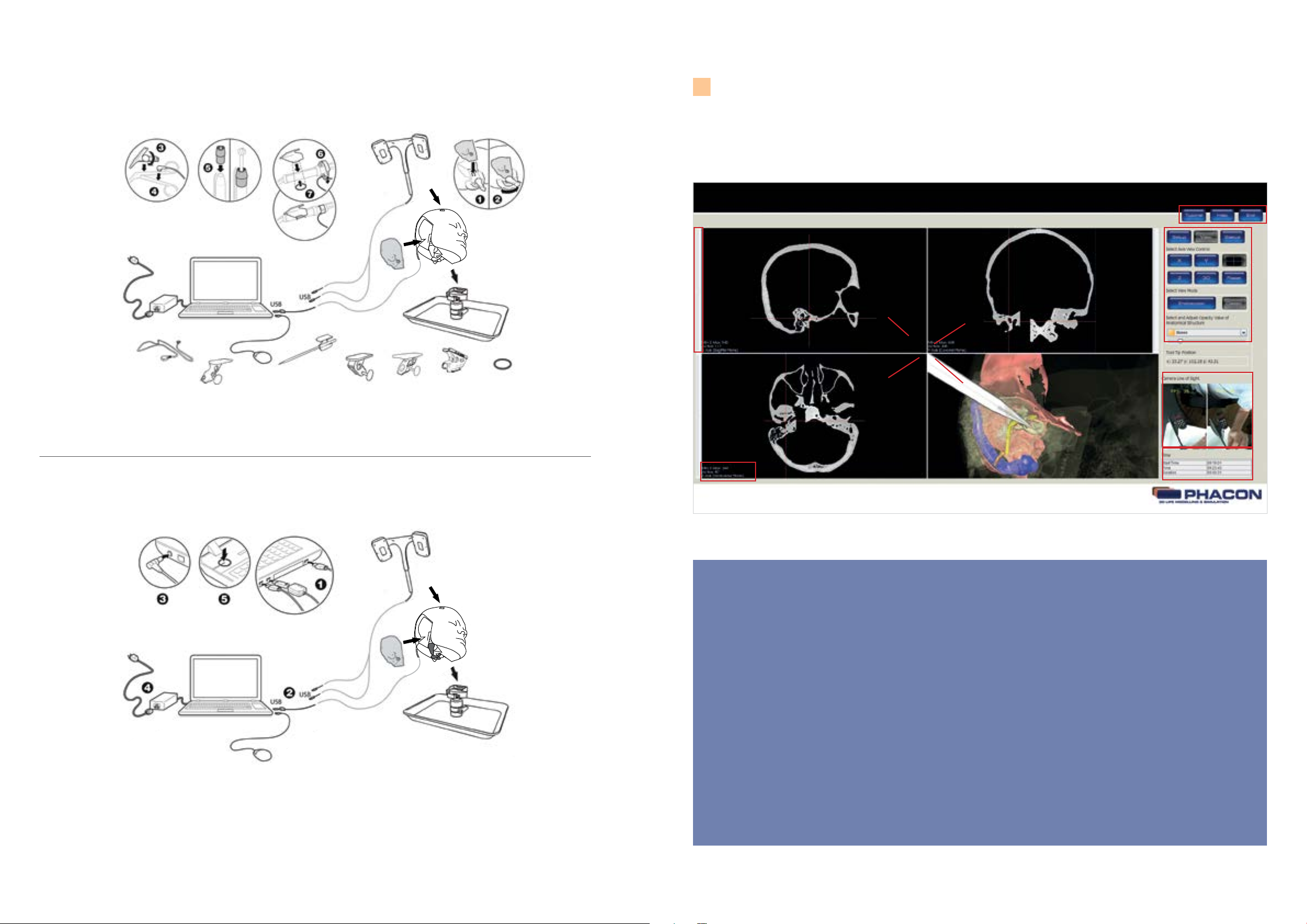
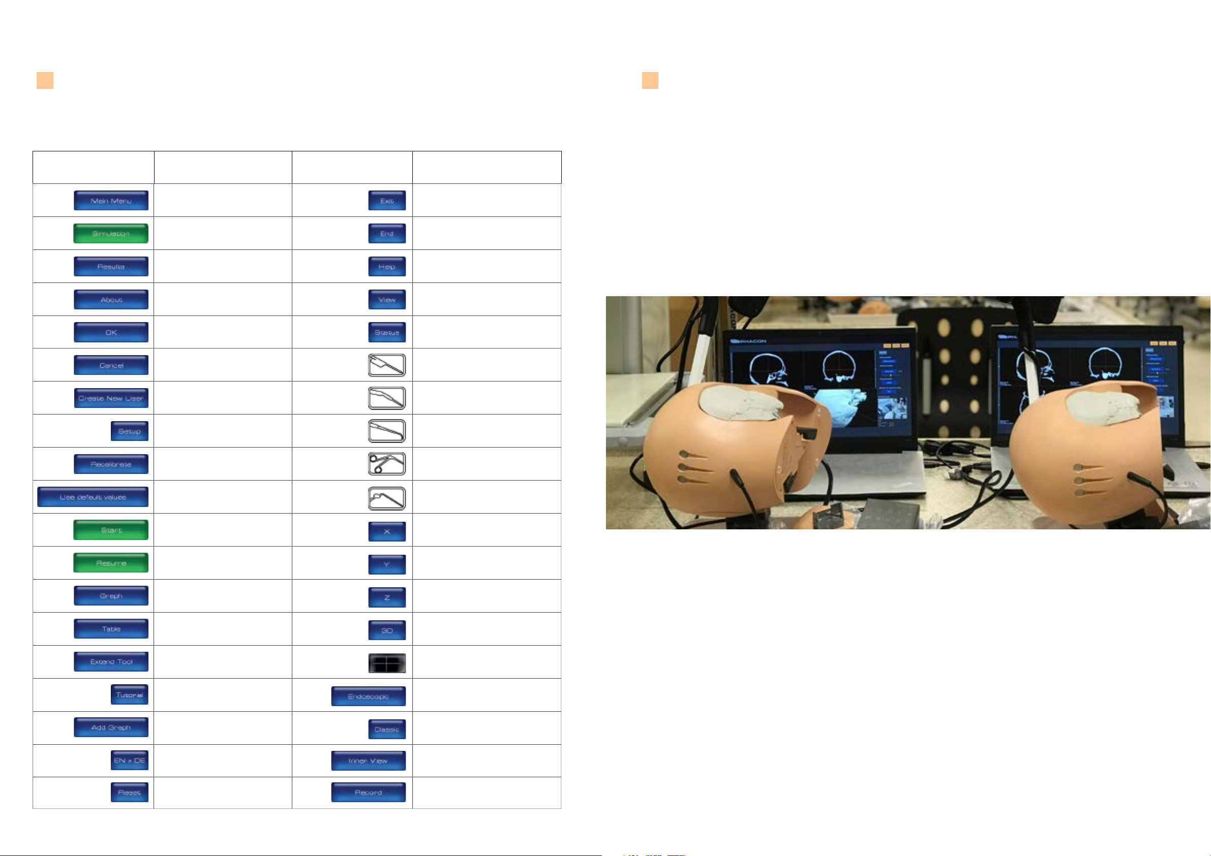
The PHACON Temporal Bone Trainer is a modular system.
This trainer consists of a head model connected to a laptop comput-
er congured with special training system soware. The head model
is designed to receive a disposable temporal bone insert. The insert
is intended to be used for a single surgical simulation and discarded
aer use. The trainer provides visual and tactile feedback through the
laptop computer’s graphical user interface (GUI) and the use of real
surgical instruments.
Through the use of sensors, the bone insert is designed to detect
whether the surgical instrument has made contact with a critical ana-
tomical risk structure, like the Dura Mater. A visual and audible signal
is provided during the simulation if the risk structure is injured.
The head model is also equipped with a navigation camera. The cam-
era used in combination with the navigation feature provides the ca-
pability to monitor the tip location of a pointer or surgical instrument.
The training system soware will record the duration of the training
simulation, the type of risk structure injured, and the number of risk
structures injured. Aer the training simulation, this information may
be viewed and statistically evaluated.
OTHER GENERAL WARNINGS
Please put the trainer and laptop on a rm surface that can not tilt.
Do not place the laptop with its power cable directly to the PHACON
assistant with his head and PHACON patient. Water injection risk!
If you nd that the insulation on the cables is loose, please replace it
and do not use any damaged parts.
Always use your surgical instruments according to the intended use of
the manufacturer.
Cases and packaging
WARNINGS:
The suitcase and the packaging foils are not toys and not suitable for
children. There is a risk of suocation!
The packaging material is not suitable for eating.
Packaging waste is not to be disposed of via normal household waste.
Please think about your environment.
There is a risk of tripping due to loose cables.
There is a risk of strangulation due to cables.
Please do not use any liquid food or drink during use.
!

98
TRAINER COMPONENTS
Laptop with navigation soware
A
Power supply suitable for the
voltage of the country
B
Mouse
C
Navigation camera
D
Temporal bone head
E
Ground cable (3x)
F
Holder Tray with adjustable head xation
G
Instrument tracker for a ballprobe
H
Pointer
I
Instrument tracker suction device
J
Instrument tracker for blakesley or trucut
K
3 x Instrument tracker for dierent drills
L
O-Ring for xation of the drill tracker
M
NOTE
Every PHACON Temporal
Bone Trainer with naviga-
tion contains a navigation
camera which is labeled
with a part number at the
side surface (SCXXXXX). The
belonging trainer laptop
shows the same number
labeled on its underside.
If you are using more than
one trainer, please make
sure to use the right combi-
nation of camera and laptop
(equal part number).
!
Warnings: Injury through clamp! When the head is placed on the support tray and when the patient is inserted into the head, there is the
danger of being trapped the ngers. Injury through stabbing! The included pointer can lead to serious or fatal injuries if used improperly.
INSTRUCTIONS
PREPARE THE TRAINER FOR USE
Set Up the Head (Figure 1)
WARNINGS:
• ALWAYS place the power cord away from personnel trac areas to
eliminate a trip hazard. NEVER place the power cord near to water or
liquids to prevent a shock hazard.
• DO NOT expose any electronic component of this system to fluid, ex-
cessive humidity, or heat.
CAUTIONS:
• ALWAYS place cables and connectors away from any possible crush
hazard.
• ALWAYS connect a suction canister and apply a source of vacuum to
the head before operating the system to facilitate the removal of debris
during training.
NOTES:
• The use of irrigation is recommended during the drilling and/or milling
procedure.
• Make sure the head with tray and the laptop computer are optimally
placed to facilitate easy access.
1. Install the head onto the ball joint plate until it snaps into place.*
2. Rotate the head lever and head lever lock to fasten the head to the
ball-joint mounting plate.
3. Rotate the head to the desired position. Rotate the ball-joint lever/
lock to secure the head in place.
4. Connect the camera USB extension cord to the USB cable plug of the
navigation camera.
5. Install the navigation camera into the navigation camera cradle of the
head and attach the navigation camera.
6. Connect a suction tube between the suction port of the head and a
facility suction canister.
7. Connect a suction tube between the suction canister and a facility vac-
uum source.
Install the Temporal Bone Insert and Connect the Surgical
Instruments (Figure 2)
NOTE: To install or remove the temporal bone insert, always orient the
lever in a downward position.
1. Install the temporal bone insert into the temporal bone insert cavity
of the head.*
2. Rotate the T-Bone insert lever to secure the temporal bone insert to
the head.
NOTE: The use of a manual instrument is optional.
3. Place the manual instrument tracker onto a manual instrument (for-
ceps, for example). Secure the manual instrument tracker to the manual
instrument by hand tightening the thumb screw.*
4. Apply the magnet of the ground cable from the head to the manual
instrument.
5. Place the drill tracker onto the housing of the drill. Fasten the drill
tracker to the body of the drill using the O-ring.*
Connect the Laptop Computer* (Figure 3)
1. Connect the USB cable from the head, the navigation camera, and the
laptop computer mouse to a USB port on the laptop computer.
2. Connect the plug of the laptop computer power adapter into the pow-
er port of the laptop computer.
3. Connect the power cord between the laptop computer power adapter
and the facility power source.
4. Press the power button to turn the laptop computer on.
NOTE: See the instructions for use supplied with the laptop computer.
!
Figure 1
Set Up the Head
!
*Warnings: Injury through clamp! When the head is placed on the ball-and-socket joint, there is a risk that the ngers will get caught. When
you insert the camera into the head, you could pinch your ngers. There is a risk of tripping due to loose cables and a risk of strangulation
due to cables.
3 x

1110
Figure 2
Install the Temporal Bone Insert and Connect the Surgical Instruments
Figure 3
Connect the Laptop Computer
LAPTOP DISPLAY SCREEN
ATitle Menu Bar – Used to access the title bar button options, including the HELP button, the TUTORIAL button
and the END button to return to the MAIN MENU.
BPanel Menu Bar – Used to access the panel menu button options, including the SETUP button, the VIEW button,
and the STATUS button. Each button provides access to a specic panel type.
C Camera Line of Sight – Used to display the image within the navigation camera’s line of sight.
DSimulation Time – Used to display the start time of the simulation, the current time, and the duration of the
simulation session.
EWindowpanes (4) – Used to display the three computed tomography (CT) scan image views and 3-D view of the
head and Patient.
FSlice Selection Slide Bar – Used to select the slice view of the CT scan image.
GAxis Identication – Used to identify the CT scan image axis, including the x-axis (sagittal plane), the y-axis
(coronal plane), and the z-axis (transverse plane), the maximum number of slices and the current slice.
E
G
F
A
B
C
D

1312
BUTTONS
Button Definition Button Definition
Access the MAIN MENU screen to view
major menu options.
Access the SIMULATION screen to begin
a training session.
Access the RESULTS screen to view and
compare the training session data.
Access the ABOUT dialog box to view
hardware and software information.
Accept inputs, changes or selections
and return to the previous screen.
Reject inputs, changes or selections and
return to the previous screen.
Access the CREATE NEW USER dialog
box to create a new user profile, user
name and password.
Access the SETUP panel to perform
calibration of an instrument or patient.
Initiate the calibration of instruments or
patient from the SETUP panel.
Select the factory default calibration set-
tings programmed for the instrument or
Patient.
Begin a SIMULATION or training session
from the SETUP panel.
Continue a SIMULATION or training
session from the SETUP panel.
Access and view the training session
results in a graphical format.
Access and view the training session
results in a tabular format.
Virtual extension of the instrument.
Open a tutorial.
Add a graph in the result screen.
Select or toggle the language for the
software (German / English).
Reset the default settings for brightness,
contrast and slice position in the 4
windowpane in the simulation mode.
Close and exit the program.
End the SIMULATION or training
session.
Access the HELP dialog box to view
instructions for use information.
Access the VIEW panel to select or
modify a screen view or perspective.
Access the STATUS panel to view the
number of injured risk structures during
a training session.
Select the POINTER for recalibration
and use.
Select the angled drill for recalibration
and use.
Select the ballprobe for recalibration
and use.
Select the blakesley for recalibration
and use.
Select the suction device for recalibration
and use.
Access the sagittal view of the skull CT
data as a full screen display.
Access the coronal view of the skull CT
data as a full screen display.
Access the transversal view of the skull
CT data as a full screen display.
Access the 3-D view of the Patient and skull
as a full screen display.
Return to the default 4-windowpane
screen view.
View a navigated instrument in the 3-D
windowpane as if a virtual camera was
mounted on the tip of the instrument.
View a navigated instrument without the
virtual camera option.
Access the camera view onto the transparent
cochlea.
Record a video of the camera view of the
cochlea.
Button ButtonDenition Denition
OPERATE THE TRAINER

1514
OPERATE THE TRAINER
1. Double click on the „PHACON Trainer“ icon located on the laptop computer desktop to log into the
training program.
ENTER THE APPLICATION
2. Type in your user name and password.
If you do not have an account you can create one or log in as guest.

1716
3. To create a new user, ll in your rst and last name. Dene a username, type in a password
and re-type your password. The other elds are optional.
4. From the MAIN MENU screen, click the SIMULATION button. (Fig. 3 )
(Fig. 3)
Click on the SETUP button to perform instrument and patient calibration for optimal navigation results.
See To Perform Setup for Navigation (optional) section.
Click on the START button to begin simulation without performing calibration (Fig. 4).
(Fig. 4)

1918
PERFORM SETUP FOR NAVIGATION
To calibrate your pointer and your instrument click on the icon tool calibration, “RECALIBRATE”.
NOTE
• Each instrument must be selected and calibrated before the instrument may be used in a navigated
fashion.
• To apply navigation, make sure the appropriate tracker is installed on the drill or the manual instru-
ment. The pointer is designed with a tracker and is already precalibrated.
ALWAYS make sure the round shapes of the pointer, drill tracker or instrument tracker are aligned and
visible to the navigation camera’s line of sight during any calibration. The dialog box is showing which
instrument will be calibrated. To calibrate another instrument, the selected tool can be exchanged
during the shown time in seconds. The soware automatically detects the current instrument in use.
SETUP for navigation requires tool calibration and Patient registration.
PERFORM PATIENT CALIBRATION
NOTE
• Temporal bone calibration is performed to align the head model coordinate system with the coordi-
nate system of the pointer, drill, or manual instrument.
• The ve calibration points are visible on the Temporal Bone Patient and within the 3-D windowpane
during calibration.
• Sequence numbers and a progress bar are provided in the Patient Calibration dialog window as
visual feedback during the calibration procedure.
1. Click on the RECALIBRATE button to begin the calibration process. (Fig. 6 ).
2. Hold the tip of the pointer on the rst calibration point of the Patient as indicated in the 3-D window-
pane.
3. Aer visual and audible feedback indicates successful data acq uisition, relocate the tip of the pointer
to the next calibration point as indicated in the 3-D windowpane.
4. Change the location of the pointer ve times. An INFORMATION MESSAGE pop-up will appear to
indicate the successful completion of the calibration procedure.
5 . Click on the START/RESUME button to begin or continue the simulation, respectively, if desired.
!
Warnings: External irrigation and suction may be used during the drilling and/or milling procedure of the training. NEVER allow water to
contact the laptop computer or any associated electrical connections. ALWAYS wear a face mask and eye protection during the drilling and/
or milling procedure of the training.
(Fig. 6)

2120
SELECT A VIEW DURING SIMULATION
From the panel menu bar, click on the VIEW button to access the VIEW panel options including
AXIS VIEW CONTROL, VIEW MODE and the OPACITY VALUE of an ANATOMICAL STRUCTURE (Fig. 8).
NOTE
The cross hairs visible within each windowpane represent the location of the pointer, drill or
manual instrument tip when using navigation.
(Fig. 8)
PERFORM TOOL CALIBRATION
NOTE
• Tool Calibration* is performed to determine the axis length and tip location of the pointer, drill or
manual instrument.
• Orientation calibration is the last step of Tool Calibration. Orientation calibration is performed to
determine the orientation of the pointer, drill, or manual instrument within the 3-D space.
• ALWAYS keep the tip of the pointer, drill or manual instrument in the same user-dened location
during the entire calibration procedure.
• Sequence numbers and a progress bar are provided in the TOOL CALIBRATION dialog window as
visual feedback during the calibration procedure.
1. Click on the CALIBRATE or RECALIBRATE button to begin the calibration process. Make sure the desired
tool is selected for calibration.
2. Hold the tip of the tool in a xed location on the Patient. Make sure the tracking shapes are facing the
camera and are within the camera line of sight.
3. Aer visual and audible feedback indicates successful data acq uisition, change the angle of the tool
while keeping the tip of the tool in a xed location.
• Change the angle of the tool ve times with the tip location in a xed location.
• Hold the tool perpendicular to the Patient to perform the direction calibration (Fig. 7 ). An INFORMA-
TION MESSAGE pop-up will appear to indicate the successful completion of the calibration procedure.
• Perform the Patient CALIBRATION if necessary.
•Click on the START or RESUME button to begin or continue the simulation, respectively, if desired.
Caution: Please note during the tool calibration and in the further course no clothes with conspicuous pattern. Disturbing patterns on the clothing
can cause problems with the measurement and navigation.
(Fig. 7)
PERFORM PATIENT CALIBRATION (PHACON Temporal Bone Patient with skin)
NOTE
If you want to work with a PHACON Temporal Bone Patient with skin, you have to calibrate the
PHACON Temporal Bone Trainer bilateral with the provided calibration patient (PHACON Temporal
Bone Patient without skin) rst. Therefore put the calibration patient into the head and follow the
instructions. Aer a successful calibration, exchange the calibration patient to the PHACON Temporal
Bone Patient with skin.

2322
SELECT THE AXIS VIEW
• Click on the X , Y , Z , or 3-D button to access the X , Y , Z , or 3-D surface windowpane in a full screen
view, respectively (Fig. 9 ).
• Click on the four-quadrant windowpane button to return to the default fourquadrant screen view.
• Click on the RESET button to return the X , Y , Z and 3-D view, if modied, to their original default set-
tings.
ADJUST THE QUALITY OR PERSPECTIVE OF THE X, Y and Z WINDOWPANE DISPLAY
• To adjust the brightness, click on the desired windowpane, hold down the le mouse button, and
move the mouse up and down.
• To adjust the contrast, click on the desired windowpane, hold down the le mouse button and move
the mouse le and right.
• To adjust the zoom, click on the desired windowpane, hold down the right mouse button and move the
mouse up and down. The mouse wheel may also be used.
• To pan, click on the desired windowpane, hold down the shi key and le mouse button, and move
the mouse up and down or le and right. The middle mouse button may also be used.
• When using navigation, the CT image slice is selected automatically based on the tip location of the
pointer, drill or manual instrument. To view dierent slices of a specic X , Y , or Z perspective, move the
slider of the appropriate windowpane.
ADJUST THE PERSPECTIVE OF THE 3-D WINDOWPANE DISPLAY
• To rotate, click on the 3-D windowpane, hold down the le mouse button and move the mouse.
• To zoom, click on the 3-D windowpane, hold down the right mouse button, and move the mouse up
and down. The mouse wheel may also be used.
• To pan, click on the 3-D windowpane, hold down the shi key and le mouse button, and move the
mouse up and down or le and right. The middle mouse button may also be used.
CHANGE THE VIEW MODE OF THE 3-D WINDOWPANE DISPLAY
NOTE
• The ENDOSCOPIC view button allows you to use a navigated tool as a virtual endoscope.(Fig. 10).
• The CLASSIC view button is the default 3-D windowpane display option. Click on the CLASSIC button
to view the exterior surface of the Patient. Click on the ENDOSCOPIC button to view the interior surfac-
es of the Patient when using a tool in a navigated fashion.
(Fig. 9) (Fig. 10)

2524
VIRTUALLY EXTEND THE TOOL
NOTE
• Tool extension can be performed to show the tool path during the simulation.
• To virtually extend the tool in the 3-D windowpne, click on the EX TEND TOOL button and move the slid-
er to variable extend the virtual tool extension, shown as a red line in the 3-D windowpane (Fig. 11).
ADJUST THE OPACITY VALUE OF AN ANATOMICAL STRUCTURE
The opacity of a specic anatomical structure may be changed to provide better visualization
within and behind the Patient.
1. Click on the drop-down list and select the desired anatomical structure. (Fig.12 ).
2 . Move the slider to change the opacity of the selected structure or click on the square but-
ton next to the selected structure to change opacity in steps „o“ (red), 25 % (orange), 75 %
(yellow), „on“ (green).
(Fig. 11)
(Fig. 12)

2726
VIEW THE TRANSPARENT COCHLEA
The magnied picture of the entire transparent cochlea can be displayed on the screen to
observe the electrode insertion of a cochlea implant.
1. Click on the INNER VIEW button to change to the camera mode of the cochlea. (Fig.13).
2 . Move the EX POSURE slider to adjust the brightness of the light.
3. By turning the black wheel on the lens of the camera, the focus of the camera can be set.
(Fig. 14)
FOR THE USAGE OF THE TEMPORAL BONE TRAINER
WITH TRANSPARENT COCHLEA
RECORD AND STORE A VIDEO OF THE COCHLEA
In the INNER VIEW mode, videos of electrode insertion
can be recorded and stored during the procedure.
1. Click on the RECORD button to start the recording of the
video (Fig.15 ). The designation of the button is changing
to RECORDING... which indicates that the recording has
been started.
2. To end the recording, click on the button RECORDING...
3. To save the recorded video, click on the CLASSIC but-
ton to change to the simulation mode.
NOTE
The recorded video is automatically stored in the directory:
C:/Users/SurgicalSimulator/Videos/PhaconTrainingSystem/< user name>/. The video designation automatically includes
the recording date and time and the le extension AVI (example 2014-07 -22 _ 14-40 -55 .avi).
WATCH A RECORD VIDEO OF THE COCHLEA
1. Use the key combination Windows key + D to return to the desktop.
2 . To watch the recorded videos, change to the directory
C:/Users/SurgicalSimulator/Videos/PhaconTrainingSystem/< user name>/ “
3. Click on the desired video and the Windows Media Player will start automatically to play the video.
NOTE
To alternatively watch the recorded video, click on the windows symbol in the task bar. Click on „Sur-
gical Simulator“ and open the directory „My Videos“.
(Fig. 13)
(Fig. 14)
(Fig. 15)

2928
VIEW STATUS DURING SIMULATION
From the panel menu bar, click on the STATUS button anytime during the training session to
see which risk structure was injured and the time the injury occurred (Fig.16). The start time,
current time and duration of the training session is also displayed.
OPERATE THE TRAINER
From the title menu bar, click on the END button to end the training session and return to the
MAIN MENU screen.
END THE SIMULATION OR TRAINING SESSION
VIEW THE TRAINING SESSION RESULTS
1. From the MAIN MENU screen, click on the RESU LTS button. (Fig. 17 )
2 . Click on the GRAPH or TABLE button to display the training session data in a graphical or
tabular format, respectively. (Fig. 18 )
3. Click on the MEASUREMENT drop-down list to select DURATION (MINU TES) or NUMBER OF
INJURIES.
NOTE
The DURATION (MINUTES) option will display how much time was spent in each training session.
(Fig. 16)
(Fig. 17)
(Fig. 18)

3130
VIEW THE TRAINING SESSION RESULTS
• The NUMBER OF INJURIES option will allow access to the ANATOMICAL STRUCTURE drop-down list.
(Fig.19)
4. Click on the ANATOMICAL STRUCTURE drop-down list.
5 . Select the ALL option or a specic risk structure to view the associated number of injuries
sustained during a particular training session.
OPERATE THE TRAINER
COMPARE WITH OTHER GROUP RESULTS
NOTE
The data collected during each training session is associated with the GROUP NAME select-
ed in the MAIN MENU. The training session results of each user may be compared with other
group results. (Fig. 20 ).
1. Click on the ADD GRAPH button to compare your results with other group results (Fig. 20 ).
2 . From the COMPARISON WITH OTHER GROUPS dialog box, click on the GROUP drop-down list and
select a group.
3. Click on the STATISTICAL PARAMETER drop-down list and select a statistical parameter.
NOTE
The STATISTICAL PARAMETER drop-down list includes maximum, minimum, mean, standard
deviation and median. The selected parameter is applied to the training session data.
4. From the COMPARISON WITH OTHER GROUPS dialog box, click on the COLOR bar and select a color.
A unique color is assigned to each selected group and the associated statistical parameter.
REMOVE A GROUP
To remove a group, click on the group name in the table COMPARE WITH OTHER GROUPS.
(Fig. 19)
(Fig. 20)

3332
CLEAN THE NAVIGATION CAMERA
CAUTION: If the lens is soiled, DO NOT touch the lens.
NOTES
1. Remove debris from the navigation camera using a facility vacuum source.
2. Wipe the surface of the navigation camera body and cable with a so cloth dampened with water.
3. Dip a cotton swab into a lens cleaning fluid and soly wipe the lens. Make sure all the debris is removed from
the lens surface.
4. When the cleaning fluid has evaporated, use a lens cleaning tissue to soly wipe the lens. Wipe from the center
of the lens to the edge of the lens in a counterclockwise direction.
PERIODIC MAINTENANCE
CLEANING
!Warnings:
Upon initial receipt and before each use, operate the equipment and inspect each component for damage. DO
NOT use any component if damage is apparent.
Perform recommended maintenance as indicated in these instructions. Only trained and experienced healthcare
professionals should maintain this equipment.
DO NOT service this equipment. If you require service, contact your PHACON sales representative.
NOTE: If any component must be discarded and replaced, see the Disposal/ Recycle section and the Accessory
Information section.
CLEAN THE HEAD
NOTES
• Make sure the Patient has been removed from the head and the head has been removed from the tray.
• Thoroughly remove all debris from the Patient lever to make sure the lever has complete freedom of movement.
Failure to comply may prevent the proper installation of the temporal bone insert into the bone cavity
during set up.
1. Remove loose debris from the surface of the head, including the mounting plate, cables, and suction port
using an external vacuum source.
2 . Carefully remove all debris from the risk structure contact pins of the head using a dry brush and an external
vacuum source.
3. While articulating the Patient lever, remove all debris from around the lever using a dry brush and an
external vacuum source. Make sure the lever has complete freedom of movement.
4 . Remove all debris from the spillways within the head using a dry brush and an external vacuum source.
Make sure the spillways are clear to allow water to low freely during the use of irrigation.
5 . Wipe all the surfaces of the head, including the contact pins, insert lever, and spillways with a so cloth wet
with water.
See the Cleaning section.Lens is covered by debris.
Navigation Camera with
Thumb Screw
Replace the camera or thumb screw.
See the Accessory Information section.
Surface is cracked or broken. Lens is
scratched. USB cable or USB exten-
sion cable insulation is cut or frayed.
Thumb screw is damaged or missing.
See the Cleaning section.Contact pins are covered with debris.
T-Bone insert lever is soiled and/or
does not move freely.
Before each use Laptop Computer See the instructions for use supplied
with the laptop computer.
Replace the laptop computer. See the
Accessory Information section.
INTERVAL COMPONENT ACTION
CRITERIA
The laptop computer is operating
improperly or is damaged.
Head Replace the module. See the Accessory
Information section.
Model surface, suction port, or
mounting plate is cracked or broken.
Contact pins are bent or broken.
T-Bone insert lever is broken. USB
cable or instrument ground cable in-
sulation is cut or frayed. Ground
cable with magnet or hook-and-loop
tape is damaged.
Head Holder with Tray Replace the head holder. See the
Accessory Information section.
Holder surface or ball-joint mounting
plate is cracked or broken. Lever(s)
or lock(s) are broken or damaged.
See the Cleaning section.Ball-joint mounting plate is soiled
and/or does not move freely.
Lever(s) or lock(s) are soiled and/or
do not move freely.
Pointer Replace the pointer. See the Accessory
Information section.
Surface or tip is cracked or broken.
Before each use Manual Instrument
Tracker with Thumb Screw
Replace the tracker. See the Accessory
Information section.
Surface is cracked or broken. Thumb
screw is damaged or missing.
Drill Tracker with O-ring Replace the tracker or O-ring. See the
Accessory Information section.
Surface is cracked or broken. O-ring
is damaged or missing.
Electrical Bur Adapter Replace the electrical bur adapter. See
the Accessory Information section.
Adapter is damaged or missing.

3534
CLEAN THE HEAD HOLDER WITH TRAY
NOTES
1. Remove loose debris from the exterior of the tray using an external vacuum source.
2 . While articulating the ball-joint mount and each lever, remove all debris from the ball-joint mount using a
dry brush and an external vacuum source. Make sure the ball-joint mount and levers have complete
freedom of movement.
3. Wipe all the surfaces of the tray, including the ball-joint mount and each lever, with a so cloth wet with
water.
CLEAN THE TRAINER ACCESSORIES
NOTES
1. Wipe all the trainer accessories, including the pointer, trackers, cables and electrical bur adapter with a
so cloth wet with water.
2. Aer all the trainer components and accessories have been cleaned properly, see the Storage and Handling
section.
!
Warnings: ALWAYS disconnect the laptop computer from the facility power source before cleaning. See the instructions for use supplied with
the laptop computer. ALWAYS disconnect and remove all system components from the laptop computer before cleaning system components.
Cautions: ALWAYS clean the surgical instruments aer a training session. See the instructions for use and/or care instructions supplied with
the surgical instrument. DO NOT sterilize this training system or any component of the system. DO NOT use solvents, lubricants, or other chem-
icals, unless otherwise specied. DO NOT allow a liquid to run directly into any electrical or mechanical connection or opening. Moisture may
cause corrosion to electrical and/or mechanical components. DO NOT bend any connector pins during cleaning.
The ground cable with magnet is not in-
stalled on the manual instrument body or
is not making contact with the manual in-
strument body.
Make sure the ground cable with magnet
is installed properly.
See the To Install the Temporal Bone Insert
and Connect Surgical Instruments section.
The trainer is not detecting critical risk
structures.
PROBLEM CAUSE ACTION
TROUBLESHOOTING
Choose right graphic adapter NVIDIA
1: Open the selection window (context menu) with a right click on your
desktop and choose NVIDIA Control Panel.
2: Select the “Manage 3D settings” in the le column of the NVIDIA
Control Panel.
3: In the Global Settings klick on “High-performance NVIDIA processor”.
4: If the “Apply” button does not appear, please select “High-performance
NVIDIA processor” again.
5: Save settings by click on the “apply” button.
5.
4.
3.
2.
The navigation system is not functioning
or is not functioning properly.
The soware application locks up. The application is experiencing an inter-
nal malfunction.
Press the CTRL/ALT/Delete buttons simultane-
ously to perform a so reboot. Press the ON/
OFF button to perform a hard reboot.
PROBLEM CAUSE ACTION
TROUBLESHOOTING
The camera lens is covered with debris. Clean the camera lens. See the To Clean the
Navigation Camera section.
An unobstructed lineof- sight does not
exist between the navigation camera lens
and the tracker.
Make sure the lineof–sight between the
navigation camera lens and the tracker is
unobstructed.
The navigation system is not accurate
based on visual indications.
The pointer, drill, or instrument is out of
calibration.
Recalibrate the pointer, drill, or instrument.
See the Perform Tool Calibration section.
During scrolling through the CT-images,
always the same area is shown.
The view mode ENDOSCOPIC is
enabled.
Change to the Classic mode in the view
panel options.
The virtual 3-D model has a delayed
reaction.
The notebook is accu driven. The power
supply is not connected.
Connect the power supply.
An instrument tracker is in the line-of-sight
of the camera in the classic mode.
Remove the tracker from the line-of-sight
of the camera.
The electrical bur adapter is not installed
on the drill attachment or the bur adapter
is damaged and not making contact with the
cutting accessory.
Make sure the electrical bur adapter is in-
stalled properly. See the To Install the Tempo-
ral Bone Insert and Connect Surgical Instru-
ments section. Replace the adapter if damage
is apparent. See the Accessory Information
section.
The ground cable with hook-and-loop tape
is not installed on the drill body or is not
making contact with the drill body.
Make sure the ground cable with hook-and-
loop tape is installed properly.
See the To Install the Temporal Bone Insert
and Connect Surgical Instruments section.
The temporal bone insert is out of cali-
bration.
Recalibrate the bone insert. See the To
Perform T-Bone Calibration section.

3736
5. Insert the two head mounting plates into the recess like on
the picture.
Follow the current local regulations governing environmental protection to recycle or dispose of electrical
equipment at the end of its useful life.
PHACON GmbH
Druckereistrasse 11
04159 Leipzig
Germany
Tel.: + 49 (0)3 41 47 83 97 35
e-mail: support@phacon.de
www.phacon.de
Store the equipment within the specied environmental condition value(s) throughout its useful life. See the
Specications section. To ensure the longevity, performance and safety of this equipment, use the original
packaging materials when transporting this equipment.
STORAGE AND HANDLING
RECYCLING
SUPPORT
1. First insert the manual into the recess.
Then insert the holder tray on the same position.
2. Lay the camera on top and position the two camera arms into
the recess next to the tray, the lenses facing upwards. The stem
lies to the le of the head xation.
3. You can place the PHACON Temporal Bone Patient next to the
camera.
4. Cover the camera, holder tray and the patient with the second
layer of foam, containing a recess for the tracker box.
6. Place the head in the free space on the top of the holder tray.
Now you can close the case lid top gently.
TRAINER STORAGE – HOW TO PACK THE TRANSPORT CASE?
MESSAGE CAUSE ACTION
The LOGIN password or user name
is/are incorrect.
Enter correct LOGIN password or user
name. Pay attention to case sensitivity.
The group name eld was le empty.
Please enter a unique group name.
The required eld data was not provided. CEnter a group name (maximum of 150
characters).
The entered group name already exists
in the trainer. Please enter a unique
group name.
The entered group name is already used. Enter a new group name into the trainer
(maximum of 150 characters).
A maximum of 150 characters is allowed. The entered group name consists of
more than 150 characters.
Enter a group name with a maximum of
150 characters.
The instrument or patient calibration
failed.
Recalibrate the instrument or patient or
use the classic.
The calibration was not successful.
In the setup menu:
No camera found.
The camera is not connected to the
notebook.
Make sure the camera is connected to
the notebook and click on TEST CONNECTION.
No camera found. The camera is not connected to the
notebook.
Make sure the camera is connected to
the notebook and click on TEST
CONNECTION.
The LOGIN password or user name
is/are incorrect. Please try again.
ERROR MESSAGES

3938
PRODUCT WARRANTIES
PHACON END USER WARRANTIES
PHACON Surgical Training Hardware, Instruments and Disposables (collectively, the “Products”) are
warranted to the original purchaser for a period of one year from the date of purchase. Products are
warranted to be free from defects in material and workmanship. The foregoing warranty covers parts,
labor, and travel if maintained and operated in accordance with manufacturer’s instructions for use.
Abnormal wear and tear or damage caused by misuse or by failure to perform normal and routine
maintenance as set out in the User Manual, or as demonstrated by an authorized PHACON or PHACON
designee’s representative, is not covered by this warranty. In order to ensure safe operation of the
Products, only PHACON accessories should be used. PHACON reserves the right to invalidate product
warranties if Products are used with accessories not manufactured by PHACON or if repairs are performed
by any party other than authorized PHACON repair personnel.
Except as set forth above, phacon makes no warranties with respect to the products or soware, express
or implied, including but not limited to, any warranties of merchantability or tness for particular purpose.
The sole liability of PHACON in the event of a breach of the above warranties is the obligation to rep or
replace the products as provided above.
In no event shall PHACON be liable for any damages resulting from or related to defects in the product
or soware, including, but not limited to, damages resulting from a loss of data or from a trainer or
hardware non-compatibility or a trainer “crash” resulting from the use of the soware.
In no event shall PHACON be liable for any indirect, special or consequential damages, lost prots or
lost business information arising out of or related to the product or soware even if PHACON has been
advised of the possibility thereof.
PHACON GmbH
Druckereistrasse 11
04159 Leipzig
Table of contents
Popular Educational Equipment manuals by other brands

Rompa
Rompa 19771 manual

Rompa
Rompa Talking Card manual

promethean
promethean Chromebox 2 user guide

PASCO
PASCO ME-9454 instruction manual

Nasco Healthcare
Nasco Healthcare Simulaids Life/form Rescue Cathy instruction manual

Talk To Me Technologies
Talk To Me Technologies GoTalk NOW Plus wego A Series Quick reference guide

3D Molecular Designs
3D Molecular Designs Enzymes in Action Kit Assembly instructions

K&H
K&H fayalab NGT-501 manual

laerdal
laerdal Resusci Anne Advanced SkillTrainer user guide

hand2mind
hand2mind STEM Lab Makerspace Cart Getting started guide

Copernicus
Copernicus LLS100 Assembly guide

Copernicus
Copernicus OLC1 Assembly guide