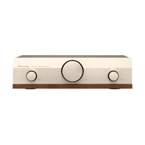
Phasemation CM-1000 User manual

Owner's Manual
CM-1000
CONTROL MEISTER
HYBRID PASSIVE ATTENUATOR
CM-1000
All manuals and user guides at all-guides.com
all-guides.com

2
Thank you for purchasing Phasemation product.
Read your Owner's Manual thoroughly for proper operation before starting to use
your equipment.
Please keep your Owner's Manual with caution.
Table of Contents
Safety Instructions............................................................................................................................................3
Usage Cautions...................................................................................................................................................4
Care of Equipment................................................................................
............................................................
4
Names and Functions (Front Panel).
..................................................................
.......................................5
Names and Functions (Rear Panel).......................................................................................................6, 7
Trouble Shooting Guide...................................................................................................................................8
Specifications
...............................................................
.......................................................................................8
All manuals and user guides at all-guides.com

3
Safety Instructions
In this owner's manual and on the product, various pictures are used to show our
customers how to use Phasemation CM‑1000 safely and properly in order to avoid
the loss of customer's assets and to protect our customers from harm.
The pictures and their meanings are as follows:
Do not use the
equipment being
broken.
In case of using the equipment in an a bnormal
state, such as seeing smoke, having strange
smell, and hearing unusual sounds or noise,
this can result in a risk of fire or electric shock.
If such an abnormal state occurs, turn the
power switch off, and endure to disconnect the
AC adaptor from the outlet. When no smoke is
confirmed, ask dealer for the repair.
Never remodeling
the equipment
Do not put the equipment apart or remodel.
This can result in a risk of fire.
Never installing the
equipment near water
Do not use the equipment in the bathroom.
This can result in a risk of fire or electric shock.
The equipment is designed for using indoors.
Do not expose the equipment to water. This
can result in a risk of failures,fire and electric
shock.
Never placing objects
filled with water on the
equipment
Do not put vases, plant and flower pots, glass,
any objects filled with skin lotion, chemicals
and water, and small metal objects on the
equipment. In case the liquids are spilled or the
small objects fall inside the equipment,
this can result in a risk of fire or electric shock.
Never putting objects
inside the equipment
In case foreign objects fall inside the equipment,
turn the amplifier's power switch off, and contact
the dealer. To keep using the equipment can
result in a risk of fire and electric shock.
WARNINGS
CAUTIONS
Installation
Do not install the equipment on the unstable
tables or unstable places. In case the equipment
falls, it can result in a risk of injury of customers.
Pay attention to the wiring of the cord so that a
foot is not caught, or the person can stumble or
the equipment can fall, which is so dangerous.
When moving, turn the power switch off, and
endure to disconnect the power plug from the
outlet and remove the connecting cord. The cord
can be damaged and this can result in a risk of
fire and electric shock.
Places which are not
suitable for installation
Do not install the equipment in the humid
or dusty environment. This can result in a
risk of fire or electric shock.
Connection
When connecting with other audio equipments
or television sets, read the manual of equipment,
turn the power switch off, and connect
according to the instructions.
All manuals and user guides at all-guides.com

4
Installation In order to use the equipment for a long time, follow the instructions below:
●Do not install near any heat sources such as direct sun light, stoves and other objects that produce heat.
●Do not use this equipment at the poorly‑ventilated, humid and dusty places.
●Do not install this equipment at unstable places such as slopes and vibrating places.
●Do not install this equipment near the window where the equipment can be exposed to rain.
●Do not install this equipment in high humidity environment.
●Avoid using this equipment on equipment generating heat such as an amplifier.
●Keep this equipment away from a power supply transformer and motor of other equipment.
Repair ●In the case of the equipment failure, consult the dealer.
Usage Cautions
Care of Equipment
◎If the equipment is covered with dust or dirt, clean only with a dry cloth.
◎If the equipment is covered with heavy dust, prepare a soft cloth and put a very thin mild
detergent. Wring the cloth and wipe off the dust and dirt. Then, clean with a dry cloth.
◎Do not use the chemical agents such as thinner, naphtha and alcohol when cleaning.
If any of them is attached to the equipment, the silk printing can be flaked or the surface
can lose metal luster.
◎To enjoy the high quality audio sound, please perform the following procedure two or
three times a year.
1.
Insert the short pin plug of accessories into the unbalance output terminals, OUTPUT (1).
2. Short the outputs.
3. Output a signal for approximately 10 seconds.
Then the magnetic quantity magnetized to the cores of output transformers will be
decreased and the operating point will become more stable.
All manuals and user guides at all-guides.com

5
Names and Functions
Front Panel
①②③
① INPUT SELECTOR knob
The input terminal corresponding to the source played can be selected.
② LEFT LEVEL & RIGHT LEVEL knobs
The volume can be controlled; so, when the knob is turned to the right (clockwise rotation),
the volume is increased; and when it is turned to the left (counterclockwise rotation),
the volume is decreased.
③ OUTPUT SELECTOR knob
The unbalance output terminals 1 and 2 of RCA pin‑connector can be selected independently,
or be turned off.
For a source having many low frequency components or for volume change of large steps (in the
region lower than 8:00 direction), a popping noise may be heard from the speakers by operating
the MASTER VOLUME knob. However, this phenomenon is not failure and the noise can occur
because of being switched to the attenuation grade which is changed by the high precision rotary
switch volume control system.
CM-1000
Note
All manuals and user guides at all-guides.com

6
④ OUTPUT‑DIRECT terminals
The audio signals to be outputted from these terminals pass through the shortest path of this
equipment because they skip the OUTPUT SELECTOR; however, these terminals should be used
only for the case that only one piece of next audio equipment is connected.
☆The OUTPUT‑DIRECT terminals are always connected regardless of the OUTPUT SELECTOR
position. It is recommended that the OUTPUT SELECTOR is set to OFF when using the
OUTPUT‑DIRECT terminals.
⑤ OUTPUT 1 & OUTPUT 2 terminals
By operating the OUTPUT SELECTOR knob, the unbalance output terminals, OUTPUT 1 & 2, of
RCA pin‑connector can be selected independently, or be turned off.
Rear Panel
④⑥⑤ ⑦ ⑧⑨
The RCA‑XLR plug of accessories should be used only for the case that the input
terminals of next equipment are XLR type. Pin assignment is as follows: pin‑1: GND,
pin‑2: HOT and pin‑3: COLD.
Pin assignment of some power amplifier may be assigned as follows: pin‑1: GND,
pin‑2: COLD and pin‑3: HOT. In this condition, the output signal is reproduced in the
opposite phase of the input signal. To play it in the proper phase, exchange wirings of
2‑pin and 3‑pin at one end of balance cable before connecting the XLR connector.
HOT
21
3
COLD
GND
CM-1000
Note
All manuals and user guides at all-guides.com
all-guides.com

7
⑥ OUTPUT‑REC terminals
The audio signals having skipped the volume control circuit to be outputted from these terminals
can be connected to external equipment such as recording equipment; however, the volume of
them cannot be controlled.
⑦ GND terminal
This is a ground reference point for audio signals.
⑧ INPUT‑DIRECT terminals
The audio signals to be inputted to these terminals pass through the shortest path of this equipment
because they skip the INPUT SELECTOR; however, these terminals should be used only for the case
that only one audio source is connected.
☆The INPUT‑DIRECT terminals are always connected regardless of the INPUT SELECTOR position.
It is recommended that the other INPUT terminals are not connected or that the INPUT SELECTOR
is set to the number of the terminals not connected, when using the INPUT‑DIRECT terminals.
⑨ INPUT terminals
Output terminals of audio equipment such as CD player, Phono amplifier and tuner can be connected
to these INPUT terminals.
The unbalance input terminals, INPUT 1 to 5, of RCA pin‑connector can be selected from among the
five sources.
Avoid connecting the ground through this terminal to equipment connected through RCA pin
connector or XLR connector, or the audio quality can be deteriorated because of forming a
ground loop among some equipment.
Utilize this terminal to connect the ground of equipment separated from audio signal such as the
motor of analog player, chassis of MC step‑up transformer or earth ground as necessary.
To insert the short pin plugs of accessories into the INPUT terminals not connected may
protect from external noise and improve S/N ratio. The short pin plugs should be used only for
INPUT 1 to 5 terminals.
Note
Note
All manuals and user guides at all-guides.com

8
Trouble Shooting Guide
Trouble Causes Measures
The sound is not
heard.
●Is the OUTPUT SELECTOR knob set to
the OFF position?
●
Aren the short pin plugs inserted to the
desired INPUT‑DIRECT, OUTPUT‑REC or
OUTPUT‑DIRECT terminals?
●
Are the short pin plug inserted into the
terminals selected by the INPUT
SELECTOR when connected to the
INPUT‑DIRECT terminals?
●Set it properly.
●Select the INPUT terminals
not connecting the short pin
plug or remove the short pin
plugs.
In case the equipment does not operate properly, check out the followings.
If it does not operate properly even after checking the advised points, contact the dealer.
A popping noise is
heard when turning
the LEFT LEVEL
or RIGHT LEVEL
knob.
●For a source having many low frequency components or for volume change
of large steps (in the region lower than 8:00 direction), a popping noise may
be heard from the speakers by operating the MASTER VOLUME knob.
However, this phenomenon is not failure and the noise can occur because
of being switched to the attenuation grade which is changed by the high
precision rotary switch volume control system.
Specifications
Product
Input impedance
Channel separation
Frequency response
Output impedance
Input/Output terminals
Dimensions (mm)
Weight
Hybrid passive attenuator
47k ohm or more
100dB or more (20Hz to 20kHz)
10Hz to 70kHz (+0, ‑3dB)
250 ohm or less
Terminals supplied by WBT
310 (width) x 86 (height) x 245 (depth)
5kg
●The appearance and specifications of this product are subject to change without notice in order to improve it.
Accessories: Six Short pin plugs , Two RCA‑XLR plugs
Kyodo Denshi Engineering Co., Ltd.
4900‑1 Ikebe‑cho, Tsuzuki‑ku, Yokohama‑shi 224‑0053
TEL 81‑45‑934‑5234
FAX 81‑45‑934‑7576
E‑mail info@phasemation.com
URL http://phasemation.com
is the original audio brand of Kyodo Denshi Engineering Co., Ltd.
All manuals and user guides at all-guides.com
Table of contents
Other Phasemation Control Unit manuals
Popular Control Unit manuals by other brands

Parker Pneumatic
Parker Pneumatic H3 Installation & service instructions

ProSoft
ProSoft MVI69E-MBS user manual

Valmet
Valmet Flowrox PVEG Installation, operation and maintenance instructions

SPX
SPX APV DELTA SDU4 operating manual

Norcold
Norcold 322 Series Replacement manual

iSMA
iSMA iSMA-B-W0202 user manual