PhDsolutions EXC-P507HDTX User manual

CH-507TX & RX
HDMI to CAT5e/6 with LAN/IR/RS-232
Operation Manual
Operation Manual
EXC-P507HDTX & RXE

SAFETY PRECAUTIONS
Please read all instructions before attempting to unpack, install or
operate this equipment and before connecting the power supply.
Please keep the following in mind as you unpack and install this
equipment:
• Always follow basic safety precautions to reduce the risk of fi re,
electrical shock and injury to persons.
• To prevent fi re or shock hazard, do not expose the unit to rain,
moisture or install this product near water.
• Never spill liquid of any kind on or into this product.
• Never push an object of any kind into this product through any
openings or empty slots in the unit, as you may damage parts
inside the unit.
• Do not attach the power supply cabling to building surfaces.
• Use only the supplied power supply unit (PSU). Do not use the PSU
if it is damaged.
• Do not allow anything to rest on the power cabling or allow any
weight to be placed upon it or any person walk on it.
• To protect the unit from overheating, do not block any vents or
openings in the unit housing that provide ventilation and allow for
suffi cient space for air to circulate around the unit.
REVISION HISTORY
VERSION NO. DATE DD/MM/YY SUMMARY OF CHANGE
VS1 29/02/12 First Release
VR2 02/03/12 PoE Support (Brand only)
VS3 23/03/12 Amended PoE function
Updated the connection diagram
and the specifi cations table
VR4 16/04/12 Add IR Distance

CONTENTS
1. Introduction............................................ 1
2. Applications........................................... 1
3. Package Contents ................................ 1
4. System Requirements............................ 1
5. Features.................................................. 2
6. Operation Controls and Functions....... 3
6.1 Transmitter Front and Rear Panels..3
6.2 Receiver Front and Rear Panels .....4
6.3. D-Sub 9 Pin Defi nitions ....................5
7. Connection Diagram ............................ 6
8. Specifi cations ........................................ 7
9. Acronyms ............................................... 8

1
1
1. INTRODUCTION
The HDMI with RS-232 over Single CAT5e/6 transmitter and receiver set
can send uncompressed audio/video over a single run of CAT5e/6
cable up to 100 m with PoE feature and the added benefi t of control
through the built-in RS-232 and IR ports and a bi-directional LAN
connection.
2. APPLICATIONS
• Household entertainment sharing and control
• Lecture room display and control
• Showroom display and control
• Meeting room presentation and control
• Classroom display and control
3. PACKAGE CONTENTS
• 1×HDMI to CAT5e/6 (with LAN/IR/RS-232) Transmitter
• 1×CAT5e/6 to HDMI (with LAN/IR/RS-232) Reciever
• 1×IR Blaster
• 1×IR Receiver
• 1×24 V/1.25 A DC Power Adaptor
• Operation Manual
4. SYSTEM REQUIREMENTS
Input HDMI source equipment such as DVD/Blu-ray player and HDMI
equipped output display (TV or monitor).
CONTENTS
1. Introduction............................................ 1
2. Applications........................................... 1
3. Package Contents ................................ 1
4. System Requirements............................ 1
5. Features.................................................. 2
6. Operation Controls and Functions....... 3
6.1 Transmitter Front and Rear Panels..3
6.2 Receiver Front and Rear Panels .....4
6.3. D-Sub 9 Pin Defi nitions ....................5
7. Connection Diagram ............................ 6
8. Specifi cations ........................................ 7
9. Acronyms ............................................... 8

2
2
5. FEATURES
• HDMI 1.4 with 3D, 4k×2k support, HDCP & DVI Compliant
• Supports CEC bypass
• Simultaneous transmission of uncompressed data over a single
100 m/328 ft CAT5e/6 cable
• Uncompressed video 1080p, 60 Hz, 36-bit
• Audio support up to 7.1CH & Dolby TrueHD, DTS-HD
• 5Play™ convergence: HDMI, LAN, PoE & Control (IR & RS-232)
• Installation Friendly
Note:
1. This system was tested with CAT6/23AWG cables, results may vary
with cables of a different specifi cation.
2. The PoE function is designed for powering compatible receiver
units only—non-PoE receivers will need their own power supply.
Receivers of another brand may not be compatible.

3
3
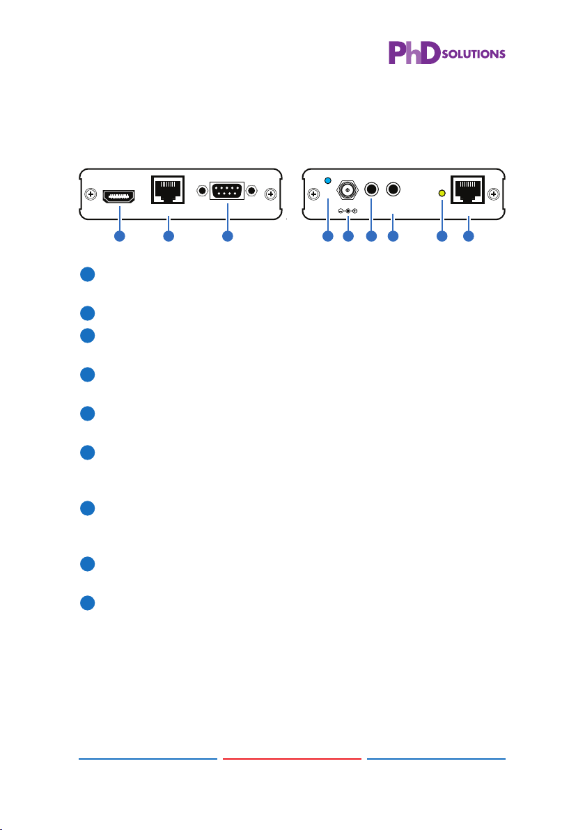
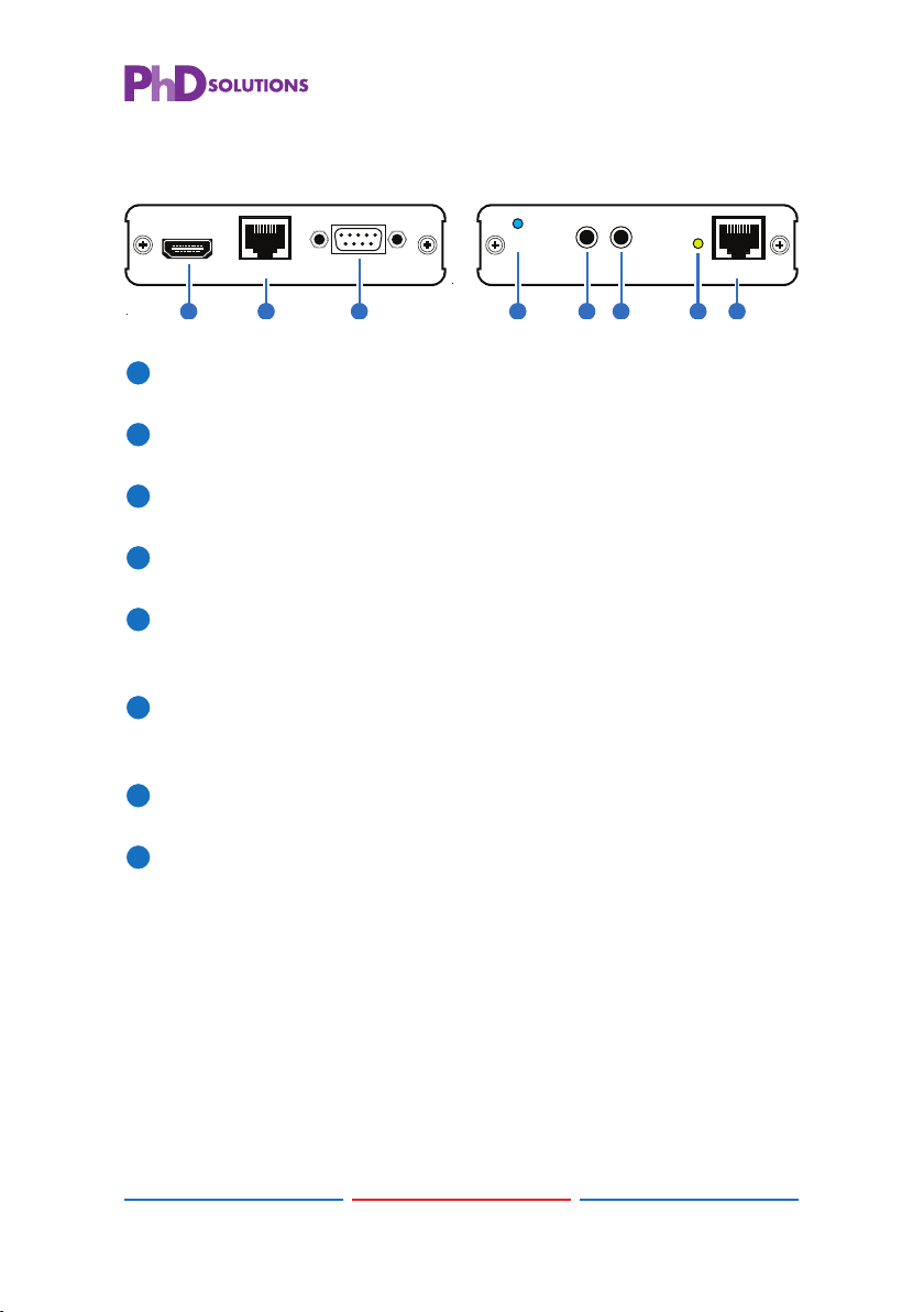
6. OPERATION CONTROLS AND FUNCTIONS
6.1 Transmitter Front and Rear Panels
RearFront
RS-232 In
LAN
HDMI In
HDMI to CAT5e/6 with LAN/IR/RS232
Transmitter
CAT5e/6 Out
Link
IR2 Extender
IR1 Blaster
DC 24V
Power
2 31 64 7 8 95
1
HDMI In: Connect to HDMI source equipment such as a DVD or Blu-
ray player.
2
LAN: Connect to an internet or network connection.
3
RS-232 In: Connect to a PC or laptop with D-Sub 9 pin male cable
for the transmission of RS-232 commands.
4
Power LED: This blue LED will illuminate when the device is
connected to a power supply.
5
DC 24V: Plug the 24 V DC power supply into the unit and connect
the adaptor to an AC outlet.
6
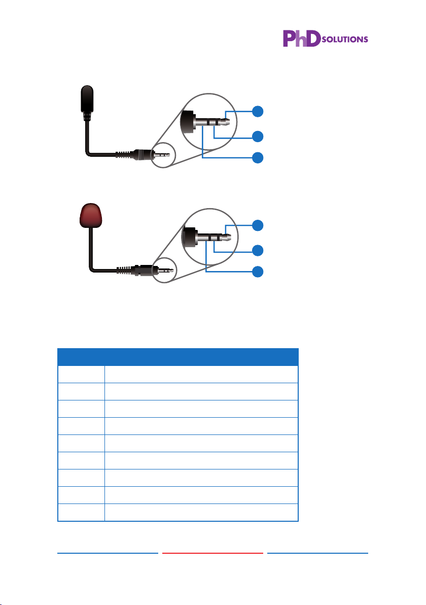
IR 1 Blaster: Connect to the supplied IR blaster cable for IR signal
transmission. Place the IR blaster in direct line-of-sight of the
equipment to be controlled.
7
IR 2 Extender: Connect to the supplied IR receiver cables for IR
signal reception. Ensure that remote being used is within the direct
line-of-sight of the IR extender.
8
Link LED: The yellow LED will illuminate when both the input and
output signals are connected.
9
CAT5e/6 Out: Connect to the reciever unit with a Single CAT5e/6
cable for tranmission of all data signals.
2
5. FEATURES
• HDMI 1.4 with 3D, 4k×2k support, HDCP & DVI Compliant
• Supports CEC bypass
• Simultaneous transmission of uncompressed data over a single
100 m/328 ft CAT5e/6 cable
• Uncompressed video 1080p, 60 Hz, 36-bit
• Audio support up to 7.1CH & Dolby TrueHD, DTS-HD
• 5Play™ convergence: HDMI, LAN, PoE & Control (IR & RS-232)
• Installation Friendly
Note:
1. This system was tested with CAT6/23AWG cables, results may vary
with cables of a different specifi cation.
2. The PoE function is designed for powering compatible receiver
units only—non-PoE receivers will need their own power supply.
Receivers of another brand may not be compatible.

4
4
6.2 Receiver Front and Rear Panels
RS-232 Out
LAN
HDMI Out
CAT5e/6 to HDMI with LAN/IR/RS232
Receiver
RearFront
CAT5e/6 In
Link
IR1 Extender
IR2 Blaster
Power
2 31 65 7 84
1
HDMI Out: Connect to a HDMI equipped TV/monitor for display of
the HDMI input source signal.
2
LAN: Connect to a PC or Laptop to the Internet or network
connection.
3
RS-232 Out: Connect to the device that is to be controlled (via
D-Sub 9 pin female cable) by RS-232 commands.
4
Power LED: This blue LED will illuminate when the device is
connected to a power supply.
5
IR 2 Blaster: Connect to the supplied IR blaster cable for IR signal
transmission. Place the IR blaster in direct line of sight of the
equipment to be controlled.
6
IR 1 Extender: Connect to the supplied IR receiver cables for IR
signal reception. Ensure that remote being used is within the direct
line-of-sight of the IR extender.
7
Link LED: The yellow LED will illuminate when both the input and
output signals are connected.
8
CAT5e/6 In: Connect to the transmitter unit with a Single CAT5e/6
cable for tranmission of all data signals.

5
5
6.3. IR Cable Pin Assignment
3
1
2
3
1
2
Power 5 V
IR Blaster Signal
NC
IR Signal
Power 5 V
Grounding
IR Receiver
IR Blaster
6.4. D-Sub 9 Pin Defi nitions
Pin Defi ne TX / RX
1 N/C
2TxD / RxD
3RxD / TxD
4 N/C
5 GND
6 N/C
7 N/C
8 N/C
9 N/C
4
6.2 Receiver Front and Rear Panels
RS-232 Out
LAN
HDMI Out
CAT5e/6 to HDMI with LAN/IR/RS232
Receiver
RearFront
CAT5e/6 In
Link
IR1 Extender
IR2 Blaster
Power
2 31 65 7 84
1
HDMI Out: Connect to a HDMI equipped TV/monitor for display of
the HDMI input source signal.
2
LAN: Connect to a PC or Laptop to the Internet or network
connection.
3
RS-232 Out: Connect to the device that is to be controlled (via
D-Sub 9 pin female cable) by RS-232 commands.
4
Power LED: This blue LED will illuminate when the device is
connected to a power supply.
5
IR 2 Blaster: Connect to the supplied IR blaster cable for IR signal
transmission. Place the IR blaster in direct line of sight of the
equipment to be controlled.
6
IR 1 Extender: Connect to the supplied IR receiver cables for IR
signal reception. Ensure that remote being used is within the direct
line-of-sight of the IR extender.
7
Link LED: The yellow LED will illuminate when both the input and
output signals are connected.
8
CAT5e/6 In: Connect to the transmitter unit with a Single CAT5e/6
cable for tranmission of all data signals.

6
6
7. CONNECTION DIAGRAM
TV or Monitor
RS-232 In
LAN
HDMI In
HDMI to CAT5e/6 with LAN/IR/RS232
Transmitter
CAT5e/6 Out
Link
IR2 Extender
IR1 Blaster
DC 24V
Power
CAT5e/6 In
Link
IR1 Extender
IR2 Blaster
Power
RS-232 Out
LAN
HDMI Out
CAT5e/6 to HDMI with LAN/IR/RS232
Receiver
1.5m
60°
1.5m
60°
7m
3m 3m
60°
7m
3m 3m
60°
RS-232 Equipped
PC or Notebook
RS-232 Equipped
HDMI Switcher
Notebook
DVD or Blu-ray Player
Internet Modem
or Router
Power
Supply
IR Blaster
HDMI
CAT5e/6
RS-232
HDMI
IR Extender
IR Extender
IR Blaster RX
TX
CAT5e/6
RS-232

7
7
8. SPECIFICATIONS
Video Bandwidth 300MHz / 9Gbps
Ethernet Speed 100 Mbps
Transmitter
Input 1×HDMI, 1×IR Extender,1×RS-232, 1×LAN
Output 1×CAT5e/6, 1×IR Blaster
Receiver
Input 1×CAT5e/6, 1×IR Extender
Output 1×HDMI, 1×RS-232, 1× IR Blaster, 1× LAN
HDMI In/Out Cable
Distance
Up to 10 Meters
CAT6 In/Out Cable
Distance
Up to 100 Meters
HDMI In/Out Supports
Resolution
480i~1080p@50/60, 1080p@24,
VGA~WUXGA
IR Frequency 30~50 kHz
ESD Protection Human Body Model:
±8 kV (air-gap discharge)
±4 kV (contact discharge)
Power Supply 24 V/1.25 A DC (US/EU Standards, CE/FCC/
UL certifi ed)
Dimensions 102 mm (W)×113 mm (D)×25 mm (H)/TX
102 mm (W)×107 mm (D)×25 mm (H)/RX
Weight 252 g (TX), 256 g (RX)
Chassis Material Aluminum
Silkscreen Color Silver
Power Consumption 13 W
Operating Temperature 0 °C~40 °C/32 °F ~104 °F
Storage Temperature −20 °C~60 °C/−4 °F~140 °F
Relative Humidity 20~90 % RH (non-condensing)

8
8
9. ACRONYMS
ACRONYM COMPLETE TERM
CAT5e Category 5 Cable
CAT6 Category 6 Cable
CEC Consumer Electronics Control
DVI Digital Visual Interface
HDCP High-bandwidth Digital Content Protection
HDMI High Defi nition Multimedia Interface
IR Infrared

SAFETY PRECAUTIONS
Please read all instructions before attempting to unpack, install or
operate this equipment and before connecting the power supply.
Please keep the following in mind as you unpack and install this
equipment:
• Always follow basic safety precautions to reduce the risk of fi re,
electrical shock and injury to persons.
• To prevent fi re or shock hazard, do not expose the unit to rain,
moisture or install this product near water.
• Never spill liquid of any kind on or into this product.
• Never push an object of any kind into this product through any
openings or empty slots in the unit, as you may damage parts
inside the unit.
• Do not attach the power supply cabling to building surfaces.
• Use only the supplied power supply unit (PSU). Do not use the PSU
if it is damaged.
• Do not allow anything to rest on the power cabling or allow any
weight to be placed upon it or any person walk on it.
• To protect the unit from overheating, do not block any vents or
openings in the unit housing that provide ventilation and allow for
suffi cient space for air to circulate around the unit.
REVISION HISTORY
VERSION NO. DATE DD/MM/YY SUMMARY OF CHANGE
VR0 10/02/14 Preliminary Release
PhD Solutions Product Warranty
Should you feel your product does not function adequately due to defects in materials or
workmanship, PhD Solutions (hereby referred to as “the warrantor”) will, for the length of the period
indicated below:
a) Repair the product with new or refurbished parts.
or
b) Replace it with a new or refurbished product.
Limited Warranty Period
Commencing from the original date of purchase, all PhD Solutions products are covered by a one
year PARTS and LABOUR warranty depending on the product.
Please contact your PhD Solutions dealer for details.
During this period there will be no charge for unit repair, replacement of parts, unit components or
replacement of product if necessary. The decision to repair or replace will be made by the warrantor.
The purchaser must mail-in or return the product to PhD Solutions during the warranty period.
This limited warranty only covers the product purchased as new and is extended to the original
purchaser only. It is non-transferable to subsequent owners, even during the warranty period.
A purchase receipt or other proof of original purchase date is required for the limited warranty service.
IF REPAIR IS NEEDED DURING THE LIMITED WARRANTY PERIOD THE PURCHASER WILL BE
REQUIRED TO PRODUCE A SALES RECEIPT/PROOF OF PURCHASE INDICATING DATE OF
PURCHASE, AMOUNT PAID AND PLACE OF PURCHASE.
Please note: THE CUSTOMER WILL BE CHARGED FOR PARTS OR REPAIR OF
ANY UNIT RECEIVED WITHOUT SUCH PROOF OF PURCHASE.
Product Service Provided
1. Damage requiring service
All units should be serviced by a PhD Solutions qualified service person.:
2. Servicing Personnel
Do not attempt to service the unit beyond that described in these operating instructions. Refer all
other servicing to authorised PhD Solutions servicing personnel.
9

10
10
HDMI Supported Resolutions Input Output
640x480@60 V V
640x480@72 V V
640x480@75 V V
720x480@60 V V
720x576p@50 V V
800x600@60 V V
800x600@72 V V
800x600@75 V V
1024x768@60 V V
1024x768@70 V V
1024x768@75 V V
1280x720@50 V V
1280x720@60 V V
1280x720p@60 V V
1280x768@60 V V
1280x800@60 V V
1280x1024@60 V V
1360x768@60 V V
1600x1200@60 V V
1920x1080i@50 V V
1920x1080i@60 V V
1920x1080p@24 V V
1920x1080p@25 V V
1920x1080p@30 V V
1920x1080p@50 V V
1920x1080p@60 V V
1920x1200@60(RB) V V
3840x2160@24/25/30 V V
4096x2160@24 V V
Return to Supplier
When shipping the unit, carefully pack and send it prepaid (preferably in the original packaging) with a
tracking number and adequate insurance. Please include a document or letter detailing the reason for
return and include a daytime telephone number and/or email address where you can be contacted.
If repair is required during the limited warranty period, the purchaser will be required to provide a
sales receipt or other proof of purchase, indicating date and location of purchase as well as the price
paid for the product. The customer will be charged for the repair or replacement of any unit received
unless such information is provided.
Warranty Limits and Exclusions
1. This Limited Warranty ONLY COVERS failures due to defects in materials or workmanship and
DOES NOT COVER normal wear and tear or cosmetic damage.
The limited warranty also DOES NOT COVER damage that occurs in shipment or failures caused by
products not supplied by the warrantor.
Failures resulting from accident, misuse, abuse, neglect, mishandling, misapplication, alteration,
incorrect installation, set-up adjustment, implementation of/to consumer controls, improper
maintenance, power line surge, lightening damage, Electro static discharge (ESD) ,modification,
service by anyone other than a manufacturer-approved service centre or factory-authorised
personnel, or damage attributable to acts of God.
2. There are no express warranties except as listed under “limited warranty coverage.” The warrantor
is not liable for incidental or consequential damage resulting from the use of this product or arising out
of any breach of this warranty.
For example: damage for lost time, the cost of having a person/persons remove or re-install
previously installed equipment, travel to and from service location, loss of or damage to
media, images, data or other recorded/stored content.
ANY PARTS AND SERVICE NOT COVERED BY THIS LIMITED WARRANTY ARE
THE RESPONSIBILITY OF THE CUSTOMER.

Premium High Denion Soluons
Home page: http://www.phdsolutions.co
This manual suits for next models
1
Table of contents
Popular Receiver manuals by other brands

WILDLIFE
WILDLIFE TRX-10S quick start guide

Bandini Industrie
Bandini Industrie GI.BI.DI. DOMINO DRC4332 Instructions for installations

THOR
THOR F-RF-RX Series Installation and user guide

Teleco
Teleco TVRCM868A01 quick start guide

Sony
Sony STR-DA3700ES operating instructions

Extron electronics
Extron electronics MTP/HDMI U R user guide