Pheonix Model Katana 120 User manual

Instruction Manual
Wingspan :
1720mm (67.7 inch)
Length :
1540 mm (60.6 inch)
Weight : 4500g - 5000g
Engine : 120 two stroke
Radio : 4 channels / 5 high torque servos
and 1standard servo
g
HOBBIRAN.COM

MAIN GEAR ASSEMBLY
(2) Main gear aluminum
(2) 75mm diameter wheel
(2) Fiberglass wheel pant
(4) 4mm x 20mm socket head screw
(4) 8mm flat washer
(4) 4mm lock washer
(2) 16mm flat washer
(2) 8mm nut
(4) Collar
(4) 3mm x 4mm screw
(2) 4mm x 85mm axle
TAIL WHEEL ASSEMBLY
(1) Tail wheel bracket w/ wire
(1) 35mm diameter wheel
(2) 3mm collar
(2) 3mm screw
(2) Nylon control clasp
(3) 3mm x 12mm wood screw
ELEVATOR CONTROL SYSTEM
(1) 3mm x 95mm metal pushrod
(1) 3mm x 170mm metal pushrod
(2) M3 clevis
(2) 3mm x 45mm screw
(2) Set aluminum control horn
(2) Nylon horn
(2) Nylon ball link
(2) Aluminum ball
(2) 3mm x 12mm screw
(2) 6mm flat washer
(2) 3mm nut
1
KIT CONTENTS: We have organized the parts as they come out of the box for better identification
during assembly. We recommend that you regroup the parts in the same manner. This will ensure you
have all of parts required before you begin assembly.
KIT CONTENTS
THROTTLE CONTROL SYSTEM
(1) 1,3mm x 500mm wire
(1) 3,5mm x 350mm nylon
pushrod housing
(1) Metal connector
(1) 4mm x 4mm machine screw
FUEL TANK
(1) Nylon fuel Tank
(1) Metal clunk
(1) Pre - assembled stopper w/ 3 tube
MISCELLANEOUS ITEMS
(1) 32mm x 675mm diameter
aluminum dihedral
(4) 6mm x 45mm nylon screw
(4) 2.6mm x 10mm wood screw
(2) 4mm x 30mm nylon screw
(2) 4mm x 35mm screw
(2) 8mm flat washer
(1) Spinner
(2) Plastic lock wing
(1) Wing fillet
Katana 120
Instruction Manual
RUDDER CONTROL SYSTEM
(1) 3mm x 105mm metal pushrod
(1) M3 Clevis
(1) 3mm x 50mm screw
(1) Set aluminum control horn
(1) Nylon horn
(1) Nylon ball link
(1) Aluminum ball
(1) 3mm x 12mm screw
(1) 6mm flat washer
(1) 3mm nut
AILERON CONTROL SYSTEM
(2) 3mm x 65mm metal pushrod
(2) M3 Clevis
(2) 3mm x 50mm screw
(2) Set aluminum control horn
(2) Nylon horn
(2) Nylon ball link
(2) Aluminum ball
(2) 3mm x 12mm screw
(2) 6mm flat washer
(2) 3mm nut
MOTOR MOUNT ASSEMBLY
(4) 4mm x 25mm screw
(4) 4mm lock washer
(4) 8mm flat washer
(4) 4mm x 30mm screw
(4) 4mm lock washer
(8) 4mm nut
(2) Engine mount

TOOLS AND SUPPLIES NEEDED
• Medium C/A glue
• 30 minute epoxy
• 6 minute epoxy
• Hand or electric drill
• Assorted drill bits
• Modeling knife
• Straight edge ruler
SUGGESTION
To avoid scratching your new airplane, do not unwrap
the pieces until they are needed for assembly. Cover
your workbench with an old towel or brown paper,
both to protect the aircraft and to protect the table.
Keep a couple of jars or bowls handy to hold the
small parts after you open the bag.
NOTE:
1. Please trial fit all the parts. Make sure you have
the correct parts and that they fit and are aligned
properly before gluing! This will assure proper
assembly. The KATANA 120 is hand made from
natural materials, every plane is unique and
minor adjustments may have to be made.
However, you should find the fit superior and
assembly simple.
2. The painted and plastic parts used in this kit are
fuel proof. However, they are not tolerant of many
harsh chemicals including the following: paint
thinner, C/A glue accelerator, C/A glue debonder
and acetone. Do not let these chemicals come in
contact with the colors on the covering and the
plastic parts.
3. The KATANA 120 will perform 3-D aerobatics
easily if you use the largest engines
recommended within the engine range. If you
setup your airplane to do 3D maneuvers, you
will need to be throttle conscious; that is,
never apply full throttle on straight and level
flying or in dives to prevent flutter.
SAFETY PRECAUTION:
• This is not a toy.
• Be sure that no other flyers are using your radio
frequency.
• Do not smoke near fuel.
• Store fuel in a cool, dry place, away from
children and pets.
• Wear safety glasses.
• The glow plug clip must be securely attached to
the glow plug.
• Do not flip the propeller with your fingers.
• Keep loose clothing and wires away from the propeller.
PREPARATIONS
Remove the tape and separate the ailerons
from the wing and the elevators from the stab.
Use a covering iron with a covering sock on
high heat to tighten the covering if necessary.
Apply pressure over sheeted areas to
thoroughly bond the covering to the wood.
• Do not start the engine if people are near. Do not
stand in line with the side of the propeller.
• Make engine adjustments from behind the propeller
only. Do not reach around the spinning propeller.
INSTALLING THE AILERONS
1. Drill a 2.4mm hole, 13mm deep in the center of
each hinge slot to allow the CA to “wick” in. Use
the modeling knife to clean out the slots.
2. Use the modeling knife to cut a strip of covering
from the hinge slots in the wing and aileron.
3. Locate the four CA hinge strip. Snip off the
corners so they go in easier.
2
Katana 120
Instruction Manual
CUT THE COVERING
AWAY FROM THE SLOT
DRILL A HOLE
DEEP, IN CENTER
OF HINGE SLOT
1
• 2 bender plier
• Wire cutters
• Masking tape
• Thread lock
• Paper towels
• Rubbing alcohol

5. Tie the string from inside the wing to the end of
the servo wire. Pull the servo wire through the
wing with the string. Tape the servo wire to the
wing to prevent it from falling back into the wing.
5
TEMPORARY PIN
TO KEEP HINGE
CENTERED
3
Katana 120
Instruction Manual
3
Remove the
covering
↑
WING TIP
2
CA glue
4
↑
WING TIP
Collar
6
Masking tape
4. Test fit the ailerons to the wing with the hinges.
If the hinges don’t remain centered, stick a pin
through the middle of the hinge to hold it in
position.
5. Remove any pins you may have inserted into
the hinges. Adjust the aileron so there is a
small gap between the LE of the aileron and
the wing. The gap should be small, just enough
to see light through or to slip a piece of paper
through.
6. Apply six drops of thin CA to the top and bottom
of each hinge. Do not use CA accelerator. After
the CA has fully hardened, test the hinges by
pulling on the aileron.
INSTALL THE AILERONS SERVOS & PUSHRODS
1. Install the servo in the wing require the use of
one 305mm servo extension for each aileron
servo. One Y-harness connector is required
and is used to allow the aileron servo to plug
into one slot in your receiver. You may have a
computer radio that allows you to plug the
servos into separate slots and then mix them
together through the radio transmitter. If you
choose to mix them with the radio rather than
the Y-harness, refer to the instructions with
your particular brand of radio.
2. Attach the servo extension to the aileron servo.
Secure the connectors together using a large
piece of heat shrink tubing, tape or other
method for securing the connectors together.
3. Turn the wing panel right side up. Using a
modeling knife, remove the covering from over
the precut servo box.
4. Using the string as a guide and pass the string from
the servo opening to the hole in the root of the wing.
Note: A weigh tied to a string can be used first,
then tied to the servo lead to pull it through.

7
9
↑
WING TIP
6. Temporarily position the aileron servo into the
servo bay. Drill a 1.6mm hole through the four
mounting holes of the servo, drilling through the
plywood mounting plate in the wing. Install and
remove a servo mounting screw into each of the
four holes. Insert a drop of thin CA into the
holes to harden the wood. After the glue has
cured, install the servo into the servo bay using
the hardware that came with your servo. Center
the servo and install a servo arm as shown.
7. Repeat step # 1 - # 6 to install the second
aileron servo in the opposite wing half.
3. Repeat step # 1 - # 2 to install the control horn
on the second aileron.
INSTALLING THE AILERON LINKAGES
The aileron linkages are assembled as shown
below.
1. Locate the pushrod wire. Slide a silicon clevis
retainer onto a clevis. Screw a M3 nut and a
threaded metal clevis onto the threaded end of
the wire. Tighten the nut against the clevis and
then install the clevis on the aileron control
horn.
INSTALLING THE CONTROL HORNS
1. The aileron has a block wood plate for mounting
the control horn. One aileron control horn in
positioned on each aileron. Using a ruler and a
pen, locate and mark the location of the control
horn. It should be mounted on the bottom side
of the aileron at the leading edge, in line with
the aileron pushrod.
7
4
Katana 120
Instruction Manual
2. Drill through the mark you made with a (3mm)
drill bit. Hard the hole with thin CA. Install the
control horn. Remember use thread locking
compound to secure.
Note: The hole on the nylon horn is aligned
with the hinge line and pushrod is aligned with
the servo arm.
10
M3 nut
M3 clevis
65mm
22mm 22mm
Aluminum washer
Aluminum control
Plastic horn 3mm Screw
RIGHT WRONG
8
IN LINE
↑
WING TIP
↑
WING TIP

5. Repeat step 1 - step 3 for the second aileron
linkage.
2. Make the same way for the plastic linkball to the
other side of the pushrod wire.
3. Plug the aileron servo into the receiver and
center the servo. Install the servo arm onto the
servo. The servo arm should be perpendicular
to the servo and point toward the middle of the
wing.
4. Center the aileron and hold it in place using a
couple of pieces of masking tape. Adjust the
linkage until the aileron and the servo arm are
both centered and then tighten the nut against
the clevis. Install the plastic linkball to the servo
arm. Remember use thread locking compound
to secure.
INSTALLING THE HORIZONTAL STABILIZER
1. Using a modeling knife, cut away the covering from
the fuselage for the stabilizer and remove it.
13
14
5
Katana 120
Instruction Manual
16
3. Check the fit of the horizontal stabilizer in its
slot. Make sure the horizontal stabilizer is
square and centered to the fuselage by taking
measurements, but don't glue anything yet.
4. With the horizontal stabilizer correctly aligned,
mark the shape of the fuselage onto the bottom
and into the top of the horizontal stabilizer
using a water soluble/ non-permanent felt-tip
pen.
2. Draw a center line onto the horizontal stabilizer
and slide it into the fuselage.
15
Center line
11
Adjust
the linkages
12
Link ball
M3 nut
M3 clevis

9. After the epoxy has fully cured, remove the
masking tape or T-pins used to hold the
stabilizer in place and carefully inspect the glue
joints. Use more epoxy to fill in any gaps that
were not filled previously and clean up the
excess using a paper towel and rubbing alcohol.
10. Repeat step 1 - step 6 from the installing
aileron for the installing elevator.
20
21
INSTALLING THE RUDDER
Repeat step 1 - step 6 from the installing aileron
for the installing elevator.
5. Remove the stabilizer. Using the lines you just
drew as a guide, carefully remove the covering
from between them using a modeling knife.
When cutting through the covering to remove it,
cut with only enough pressure to only cut
through the covering it's self. Cutting into the
balsa structure may weaken it. This could lead
to possible failure during flight.
17
6
Katana 120
Instruction Manual
6. Attach the wing to the fuselage as picture.
7. Test the position of the elevator and adjust it as
shown.
8. When you are sure that everything is aligned
correctly, mix up a generous amount of 30
minute epoxy. Apply a thin layer to the bottom
of the stabilizer mounting area and to the stabilizer
mounting platform sides in the fuselage. Insert
the stabilizer in place and re-align. Double
check all of your measurements one more time
before the epoxy cures. Remove any excess
epoxy using a paper towel and rubbing alcohol
and hold the stabilizer in place with T-pins or
masking tape.
19
18
Plastic Screw

22
24
7
Katana 120
Instruction Manual
INSTALLING THE MAIN LANDING GEAR
1. Nuts have been installed at the factory.
2. Install main landing gear into the fuselage using
(4) 4mm x 20mm socket head screws and flat
washers provided in the kit.
2. Set the tail wheel assembly in place on the
plywood plate.
3. Drill 2,6mm pilot holes through the plywood
plate.
4. Secure the tail wheel bracket in place using two
3mm x 12mm screw.
5. Align the tail wheel wire so that the wire is
parallel with the bottom of the rudder.
INSTALLING THE TAIL WHEEL
1. Using the knife cut away the wood from the
bottom of the rudder and slide the two nylon
clasps into the slot. Using C.A glue the nylon
clasps as shown.
25
27
28
23
26
Wheel
Collar

INSTALLING THE WHEEL PANTS
1. Locate the wheel pants from the hardware bag.
Mark the locations of the mounting axles onto
the wheel pants. The locations of the two
mounting holes are the middle of the wheel
opening, on right side, left side and 10mm from
the bottom of the wheel pant.
2. Using a 5mm drill bit, carefully drill two pilot
holes through the wheel pant at the TWO
marks you made.
29
8
Katana 120
Instruction Manual
!
3. Using a modeling knife, carefully cut out two
line from the margin of the hole onto the wheel
pant. Just cut only one side of the wheel pant,
where the main gear will install. Be sure to
make a left and right wheel pant.
4. Slide a 4.5mm nut/ three 16mm flat washers/
4.5mm nut/ collar/ wheel/ collar onto the axle.
5. Slide the axle assembly into the wheel pant.
There are just one nut and two flat washers
outside of the wheel pant.
6. Remove one nut, one flat washer. Attach the
main landing gear to the axle.
7. Center both collars and wheel in the middle of
the wheel pant, lock both collars in place using
a hexagon 2mm screw.
8. With the landing gear in place, tighten two nuts.
Drill
Cut
30
After installing the wheel pant, apply a small
drop of thin C/A to the bottom nut.
9. Repeat step # 1-8 to install the second wheel
pant assembly.
INSTALLING THE THROTTLE PUSHROD HOUSING
1. Place the engine into the engine mount and
align it properly with the front of the cowling.
The distance from the firewall to the front of the
engine thrust washer should [125mm]
If your engine is equipped with a remote needle
valve, we suggest installing it into the engine at
this time.
2. When satisfied with the alignment of the engine,
use a pencil and mark the mounting hole
location onto the firewall, where the throttle
pushrod will exit.
3. Now, remove the engine. Using a 5mm drill bit,
drill holes through the firewall and the forward
bulkhead at the marks made.
4. Slide the pushrod housing through the hole in
the firewall, through the hole in the forward
bulkhead, and into the servo compartment.
5. Apply a couple of drops of thin C/A to the pushrod
housing where it exits the firewall and where it
passes through the forward bulkhead. This will
secure the housing in place.
6. Using a modeling knife, cut off the nylon
pushrod housing in front of the servo tray.
16 mm flat washer
31
!
!

3. Carefully bend the second nylon tube up at a 45
degree angle (using a cigarette lighter). This
tube will be the vent tube to the muffler.
4. Carefully bend the third nylon tube down at a 45
degree angle (using a cigarette lighter). This
tube will be vent tube to the fueling valve
When the stopper assembly is installed in the
tank, the top of the vent tube should rest just
below the top surface of the tank. It should not
touch the top of the tank.
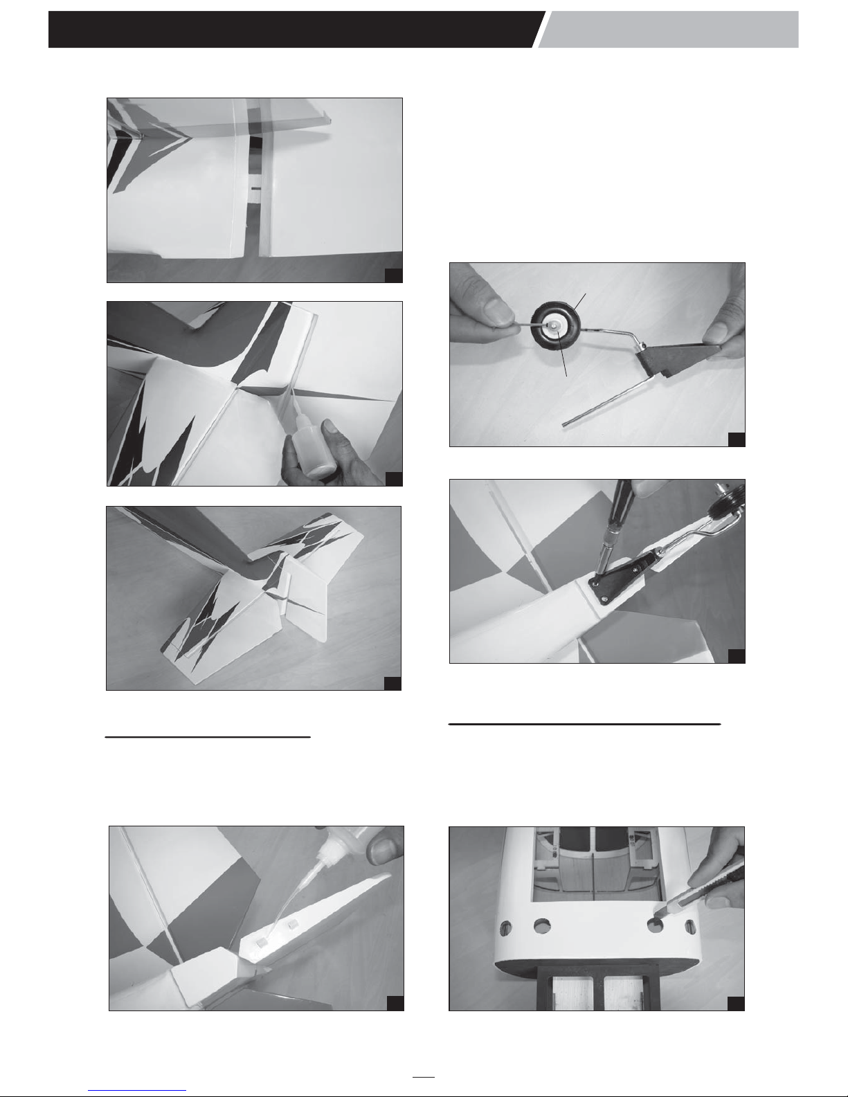
5. Test fit the stopper assembly into the tank. It
may be necessary to remove some of the
flashing around the tank opening using a
modeling knife. If flashing is present, make sure
none of it falls into the tank.
6. When satisfied with the alignment of the stopper
assembly tighten the 3mm x 20mm machine
screw until the rubber stopper expands and
seals the tank opening. Do not over tighten the
assembly as this could cause the tank to split.
7. Using a modeling knife, cut 3 lengths of fuel line
150mm long. Connect 2 lines to the 2 vent tubes
and 1 line to the fuel pickup tube in the stopper.
8. Feed three lines through the fuel tank
compartment and through the pre-drilled hole in
the firewall. Pull the lines out from behind the
engine, while guiding the fuel tank into place.
Push the fuel tank as far forward as possible,
the front of the tank should just about touch the
back of the firewall. Blow through one of the
lines to ensure the fuel lines have not become
kinked inside the fuel tank compartment. Air
should flow through easily.
Do not secure the tank into place permanently
until after balancing the airplane. You may need
to remove the tank to mount the battery in the
fuel tank compartment.
9. To secure the fuel tank in place, apply a bead of
silicon sealer to the forward area of the tank,
where it exits the fuselage behind the engine
mounting box and to the rear of the tank at the
forward bulkhead.
10. Use 6mm x 8mm hardwood to secure the fuel
tank in place by CA glue.
9
Katana 120
Instruction Manual
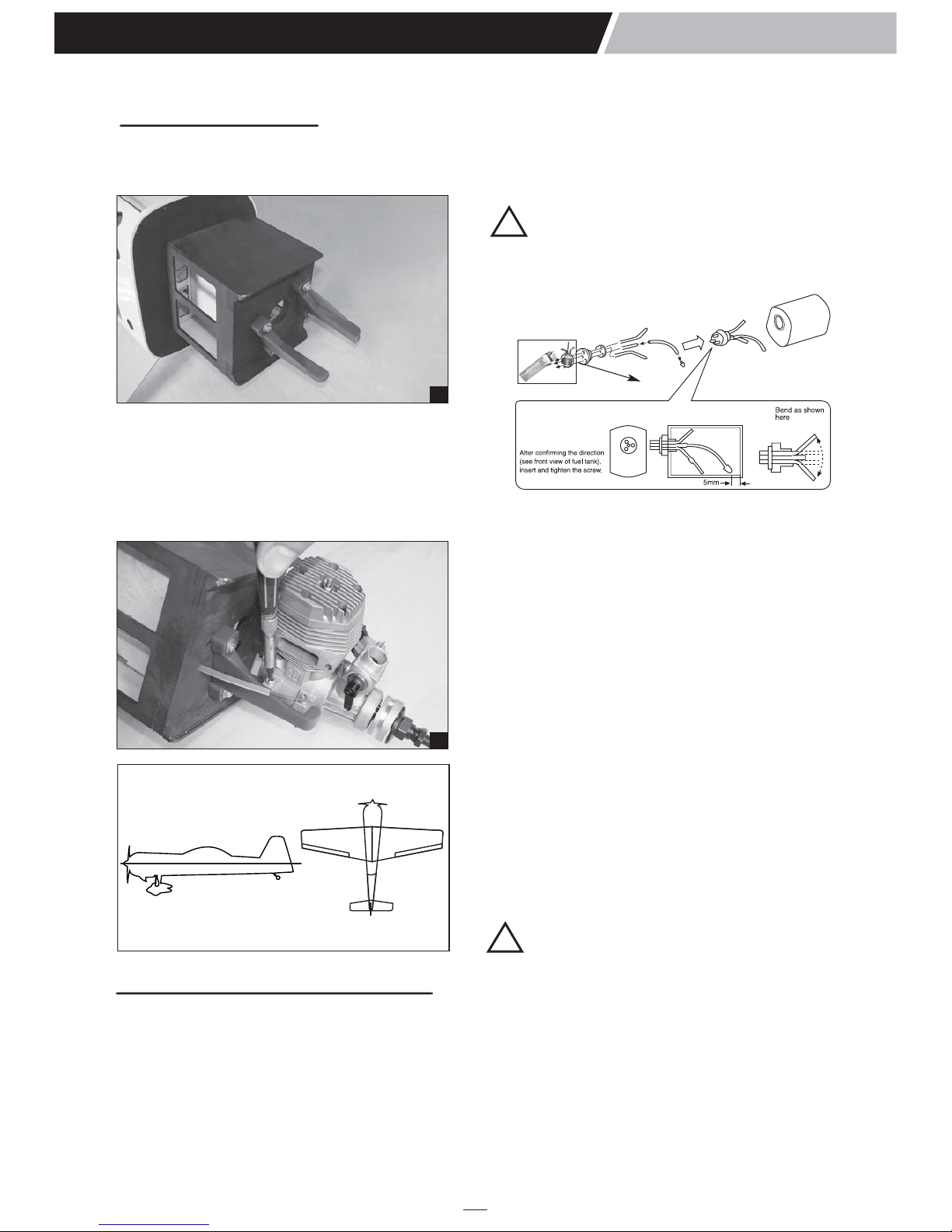
INSTALLING THE ENGINE
This manual, we used the OS 120 - two stroke
1. Install the engine mount.
2. Locate the long piece of wire used for the
throttle pushrod. One end of the wire has been
pre-bend in to a "Z" bend at the factory. This
"Z" bend should be inserted into the throttle
arm of the engine when the engine is fitted
onto the engine mount. Fit the engine to the
engine mount using the screws provided.
10down thrust
30right thrust
33
32
INSTALLING THE STOPPER ASSEMBLY
1. The stopper has been pre-assembled at the factory.
2. Using a modeling knife, cut one length of silicon
fuel line (the length of silicon fuel line is
calculated by how the weighted clunk should
rest about 8mm away from the rear of the tank
and move freely inside the tank). Connect one
end of the line to the weighted clunk and the
other end to the nylon pick up tube in the
stopper.
!
!!

170mm
22mm 22mm
10
Katana 120
Instruction Manual
38
3. The elevator has a block wood plate for
mounting the control horn. One elevator control
horn in positioned on each elevator. Using a
ruler and a pen, locate and mark the location of
the control horn. It should be mounted on the
bottom side of the elevator at the leading edge,
in line with the elevator pushrod.
4. Drill through the mark you made with a (3mm)
drill bit. Hard the hole with thin CA. Install the
control horn. Remember use thread locking
compound to secure.
Note: The hole on the nylon horn is aligned with
the hinge line and pushrod is aligned with the
servo arm.
INSTALLING THE THROTTLE SERVO
1. Install the rubber grommets and brass collets
into the elevator, rudder and throttle servos.
Test fit the servos into the servo tray. Trim the
tray if necessary to fit your servos
2. Mount the servos to the tray using the mounting
screws provided with your radio system.
INSTALLING THE ELEVATOR SERVO
1. Remove the covering from both size of the
fuselage.
2. Install two servo to the fuselage as shown.
36
37
35
→
Engine side
INSTALLING THE ELEVATOR LINKAGES
The elevator linkages are assembled as shown below
. Repeat these step as installing the aileron
linkages (Page 4 and page 5).
. Repeat these step for the second servo elevator.
34
CA glue

95mm
22mm 22mm
105mm
22mm 22mm
41
39
44
11
Katana 120
Instruction Manual
43
Control horn
42
Remove the covering
40
The elevator linkages are assembled as shown below
INSTALLING THE RUDDER SERVO
1. Remove the covering from the fuselage.
2. Install the rudder servo to the fuselage as
shown.
3. The control horn should be mounted on the
right side of the rudder at the leading edge, in
line with the rudder pushrod.
INSTALLING THE RUDDER LINKAGES
. Repeat these step as installing the aileron
linkages (Page 4 and page 5).

!
MOUNTING THE COWL
1. Remove the muffler and needle valve assembly
from the engine. Slide the fiberglass cowl over
the engine.
2. Measure and mark the locations to be cut out
for engine head clearance, needle valve,
muffler. Remove the cowl and make these cut
outs using a rotary tool with a cutting disc and a
rotary sanding drum attachment.
3. Slide the cowl back into place. Align the front of
the cowl with the crankshaft of the engine. The
front of the cowl should be positioned so the
crankshaft is in the middle of the precut
opening. Hold the cowl firmly in place using
several pieces of masking tape.
4. While holding the cowl firmly in position, drill
four 1,6mm pilot holes through both the cowl
and the side edges of the firewall.
5. Using a 3mm drill bit, enlarge the four holes in
the cowling.
Enlarging the holes through the cowl will prevent
the fiberglass from splitting when the mounting
screws are installed.
6. Slide the cowl back over the engine and secure
it in place using four 3mm x 12mm wood screws.
7. Install the muffler. Connect the fuel and
pressure lines to the carburator, muffler and
fuel filler valve. Tighten the screws completely.
FINAL ASSEMBLY
INSTALLING THE SPINNER
. Install the spinner back-plate, propeller and
spinner cone. The spinner cone is held in place
using two 3mm x 20mm wood screws.
. The propeller should not touch any part of the
spinner cone. If it dose, use a sharp modeling
knife and carefully trim away the spinner cone
where the propeller comes in contact with it.
12
Katana 120
Instruction Manual
46
Carburator
Engine head
Muffler
47
Secure
the cowl
45
INSTALLING THE THROTTLE
1.
Install one adjustable metal connector through the
third hole out from the center of one servo arm,
enlarge the hole in the servo arm using a 2mm drill
bit to accommodate the servo connector. Remove
the excess material from the arm.
After installing the adjustable metal connector
apply a small drop of thin C/A to the bottom nut.
This will prevent the connector from loosening
during flight.
2. Plug the throttle servo into the receiver and turn
on the radio system. Check to ensure that the
throttle servo output shaft is moving in the
correct direction. When the throttle stick is
moved forward from idle to full throttle, the
throttle barrel should also open and close using
this motion. If not, reverse the direction of the
servo, using the transmitter.
3. Slide the adjustable metal connector/ servo arm
assembly over the plain end of the pushrod
wire. Position the throttle stick and the throttle
trim at their lowest positions.
4. Manually push the carburator barrel fully closed.
Angle the arm back about 45 degree from
center and attach the servo arm onto the servo.
With the carburator barrel fully closed, tighten
the set screw in the adjustable metal connector.
5. Remove the excess throttle pushrod wire using
wire cutters and install the servo arm retaining
screw.

1. Glue the plastic part to the wing joiner.
2. Find the hole on the top of the wing by taking
measurements as picture below.
3. Drill through the mark you make with a 2.5mm
drill bit (Note: just through the wing joiner).
4. Secure the wing joiner using a 3mm x 25mm
wood screw.
48
Switch
INSTALLING THE SWITCH
1. The switch should be mounted on the fuselage
side, opposite the muffler, close enough to the
receiver so the lead will reach. Use the face
plate of the switch cut out and locate the
mounting holes.
2. Cut out the switch hole using a modeling knife.
Use a 2mm drill bit and drill out the two
mounting holes through the fuselage side.
3. Secure the switch in place using the two
machine screws provided with the radio
system.
t
INSTALLING THE RECEIVER AND BATTERY
1. Plug the servo leads and the switch lead into
the receiver. You may want to plug an aileron
extension into the receiver to make plugging in
the aileron servo lead easier when you are
installing the wing. Plug the battery pack lead
into the switch.
2. Wrap the receiver and battery pack in the
protective foam to protect them from vibration.
Use a rubber band or masking tape to hold the
foam in place.
3. Position the battery pack and receiver in place
and using the two zip ties for mounting them as
the picture below.
4. Using a 2mm drill bit, drill a hole through the
side of the fuselage, near the receiver, for the
antenna to exit.
13
Katana 120
Instruction Manual
49
Battery
Zip tie Zip tie
Receiver
INSTALLING and secure the wing
50
52
53
51
247mm
160mm

53
5. Glue the scooper wing to the fuselage.
140mm
BALANCING
1. It is critical that your airplane be balanced
correctly. Improper balance will cause your
plane to lose control and crash.
THE CENTER OF GRAVITY IS LOCATED
140mm BACK FROM THE LEADING EDGE
OF THE WING, AT THE FUSELAGE. This
location is recommended for initial test flying
and trimming. There is a 5mm margin forward
and aft. BALANCE A PLANE UPSIDE DOWN
WITH THE FUEL TANK EMPTY.
2. Mount the wing to the fuselage. Using a couple
of pieces of masking tape, place them on the
top side of the wing 140mm back from the
leading edge, at the fuselage sides.
3. Turn the airplane upside down. Place your
fingers on the masking tape and carefully lift
the plane .
4. If the nose of the plane falls, the plane is nose
heavy. To correct this first move the battery
pack further back in the fuselage. If this is not
possible or does not correct it, stick small
amounts of lead weight on the fuselage under
the horizontal stabilizer. If the tail of the plane
falls, the plane is tail heavy. To correct this,
move the battery and receiver forward or if this
is not possible, stick weight into the firewall.
When balanced correctly, the airplane should
sit level or slightly nose down when you lift it
up with your fingers.
LATERAL BALANCE
After you have balanced a plane on the C.G. You
should laterally balance it. Doing this will help the
airplane track straighter.
5. Turn the airplane upside down. Attach one loop
of heavy string to the engine crankshaft and
one to the tail wheel wire. With the wings level,
carefully lift the airplane by the string. This may
require two people to make it easier.
6. If one side of the wing fall, that side is heavier
than the opposite. Add small amounts of lead
weight to the bottom side of the lighter wing
half's wing tip. Follow this procedure until the
wing stays level when you lift the airplane.
14
Katana 120
Instruction Manual
3d sERVOS
The large control throws require servos with
great centering. The digital servos are second to
none in this department. Digital servos such as
the Futaba S9250 should be used on all control
surfaces of this airplane for optimum
performance.
Ailerons : 15mm up 15mm down
Elevator : 15mm up 15mm down
Rudder : 20mm right 20mm left
Aileron Control
15mm
15mm
Rudder Control
20mm
20mm
Elevator Control
15mm
15mm
CONTROL THROWS
1. We highly recommend setting up a plane using
the control throws listed.
2. The control throws should be measured at the
widest point of each control surface.
3. Check to be sure the control surfaces move in the
correct directions.
LOW RATE
3-D PERFORMANCE SETTINGS
The KATANA 120 will perform 3-D aerobatics
easily if you use the largest engines
recommended within the engine range. If you
setup your airplane to do 3D maneuvers, you
will need to be throttle conscious; that is,
never apply full throttle on straight and level
flying or in dives to prevent flutter.
Ailerons : 45mm up 45mm down
Elevator : 35mm up 35mm down
Rudder : 45mm right 45mm left
HIGH RATE (FOR 3D)
HOBBIRAN.COM
HOBBIRAN.COM

I/C FLIGHT WARNINGS
Always operate in open areas, away
from factories, hospitals, schools,
buildings and houses etc. NEVER fly
your aircraft close to people or built
up areas.
THE PROPELLER IS DANGEROUS
Keep fingers, clothing (ties, shirt
sleeves, scarves) or any other loose
objects that could be caught or drawn
in, away from the propeller. Take care
at ALL times.
Keep all onlookers (especially small
children and animals) well back from
the area of operation. This is a flying
aircraft, which will cause serious
injury in case of impact with a person
or animal.
NEVER fly near power lines, aerials
or other dangerous areas including
airports, motorways etc.
NEVER use damaged or deformed
propellers or spinners.
DO NOT dispose of empty fuel
containers on a fire, this can lead to
an explosion.
NEVER fly in wet conditions or on
windy or stormy days.
ALWAYS adjust the engine from
behind the propeller, and do not allow
any part of your body to be in line
with the propeller.
15

I/C FLIGHT GUIDELINES
Made in Vietnam
When ready to fly, first extend the
transmitter aerial.
Operate the control sticks on the
transmitter and check that the control
surfaces move freely and in the
CORRECT directions. ALWAYS land the model INTO the
wind, this ensures that the model lands
at the slowest possible speed.
Switch on the transmitter.
Switch off the transmitter.
Check that the transmitter batteries
have adequate power.
Switch off the receiver.
Switch on the receiver. ALWAYS take off into the wind.
Check that the wings are correctly
fitted to the fuselage. If the model does not respond correctly
to the controls, land it as soon as
possible and correct the fault.
Empty the fuel tank after flying, fuel left
in the tank can cause corrosion and
lead to engine problems.
Table of contents
Other Pheonix Model Toy manuals
Popular Toy manuals by other brands

Smoby
Smoby 310143 quick start guide

Eduard
Eduard Sea Fury FB.11 landing flaps quick start guide

REVELL
REVELL Custom Chopper Set 7324 Assembly instructions

Fisher-Price
Fisher-Price V3254 instruction sheet

Hasbro
Hasbro Disney's Brother Bear Tumble 'n Laugh Koda... manual

REVELL
REVELL GLOWEE 2.0 BEAST Series user manual