PHOTO
FACT8
Folder
with
ClRCUMRACE*
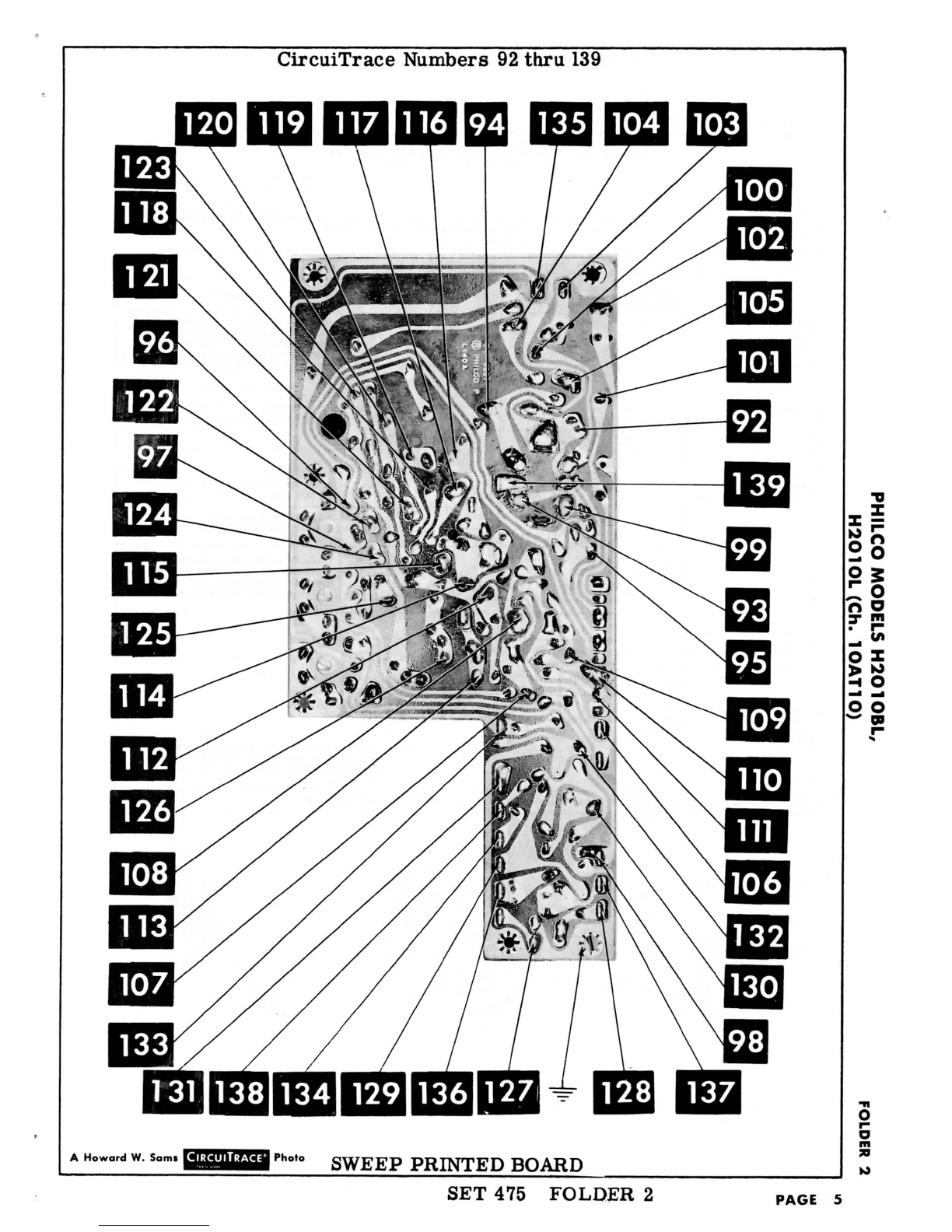
PHILCOMODELS
H2O1OBL,
H2O1OL(Ch.1OAT1O)
DISASSEMBLY
INSTRUCTIONS
CHASSIS
REMOVAL
1.
Remove
all
external
push-ontypeknobsexcept
the
Elap-
sed-Time
knob.
2.
Remove
4
metal
screws
on
bottom
holding
cabinetstand
and
lower
section
of
cabinet
tothe
chassis.
3.
Remove
2
metal
screws
at
rear
andonein
frontholding
top
plastic
housing.Removeantennaconnectionfrom
tuner.Removemetalscrewholding
ground
strap.
Re-
move
top
plastichousing.
4.
Remove
2
metal
screws
at
rear
andoneat
front
of
opti-
cal
system.
Removeopticalunit.
5.
Remove5
metal
screws
holdingbattery
mounting
bracket.
Remove
bracket.
6.
Remove
chassis.
PICTURE
TUBE
REMOVAL
1.
Remove
chassis.
2.
Removepicturetubesocket,sleeve
and
magnet
assembly,
and
HV
lead.
3.
Slide
the
picturetube
outthetopof
chassis.
MODEL
H2010L
(SAFARI)
CHASSIS
10AT10
TRADE
NAME
Philco
Models
H2010BL,
H2010L
(Safari)
(Ch.10AT10)
MANUFACTURER
Philco
Corp.,
Tioga
&
"C"
Streets,
Philadelphia,
Pa.
TYPE
SET
Portable
TelevisionReceiver
TRANSISTORS
Twenty-One
TUBES
Three
POWER
SUPPLY105-120Volts
AC,60
Cycles
or
Battery,
7.5
Volts
TUNING
RANGE
Channels
2
thru
13
VHF,
Video
IF45.
75MC,
Sound
IF
41.
25MC
(Intercarrier)
RATING
11
Watts,
. 13
Amp.
® 117
Volts
AC
SERVICING
INTHE
FIELD
SAFETY
GLASS
REMOVAL
Follow
steps
1
thru
4 of
"Disassembly
Instructions",
Remove
4
screws
holding
upper
and
lower
retainers
onop-
tical
unit.Removebeam
splitter
for
cleaning.
FUSE
One
fuse
is
used
forlow
voltagepower
supply
protection.
(Forlocation,
see
"Transistor
&
TubePlacement
Chart".)
TUNER
OSCILLATOR
ADJUSTMENTS
To
touch-up
theVHF
Oscillator,
remove
Channel
Selector
and
FineTuningknobs.
AGC
The
AGCmaybe
varied
by
means
ofa
Rangeswitch.
(For
location,
see
"
Transistor
&
TubePlacement
Chart".)
FOCUS
The
focus
maybe
varied
by
connecting
the
leadfrom
pin4
of
the
picture
tube
to
variousvoltagepoints.(Forlocation,
see
photo
"Cabinet-Rear
View".)
HORIZONTAL
OSCILLATORFIELD
ADJUSTMENTS
Coarseadjustment
ofthe
HorizontalHold
is
accomplished
by
the
proper
setting
ofthe
AuxiliaryHorizontalHold.
(For
location,
see
"Transistor
&
TubePlacement
Chart".)
BUZZ
ADJUSTMENT
To
eliminate
intercarrier
buzz,adjust
the
Discriminator
secondary
(A12)
located
ontopof
chassis.
CENTERING
Centering
is
accomplished
by2
magnetic
rings
andbythe
beamaligningmagnet,locatedbehindyoke
onthe
neck
of
the
picture
tube.
oo
?3
"O
n
O
K)
3
O
So
HOWARD
W.
SAMS
&
CO.,INC.Indianapolis
6,
Indiana
The
listing
ofany
availablereplacementparthereindoes
not
constitute
inany
case
a
recommendation,
warranty
or
guaranty
by
Howard
W.
Sams
&
Co.,
Inc.,
astothe
quality
and
suitability
of
such
replacementpart.
The
numbers
of
these
parts
havebeencompiled
from
information
furnished
to
Howard
W.
Sams
&
Co.,
Inc.,
bythe
manufacturers
of
JA723
the
particulartype
of
replacementpart
listed.
Repro-
duction
or
use,
without
express
permission,
of
editorial
or
pictorialcontent,
inany
manner,
is
prohibited.
No
patent
liability
is
assumed
with
respect
totheuseofthe
informa-
tion
contained
herein.
©
1960
Howard
W.
Sams
&
Co.,
Inc.,
Indianapolis
6,
Indiana.Printed
in
U.S.
of
America
DATE
2-60
SET
475
FOLDER
2