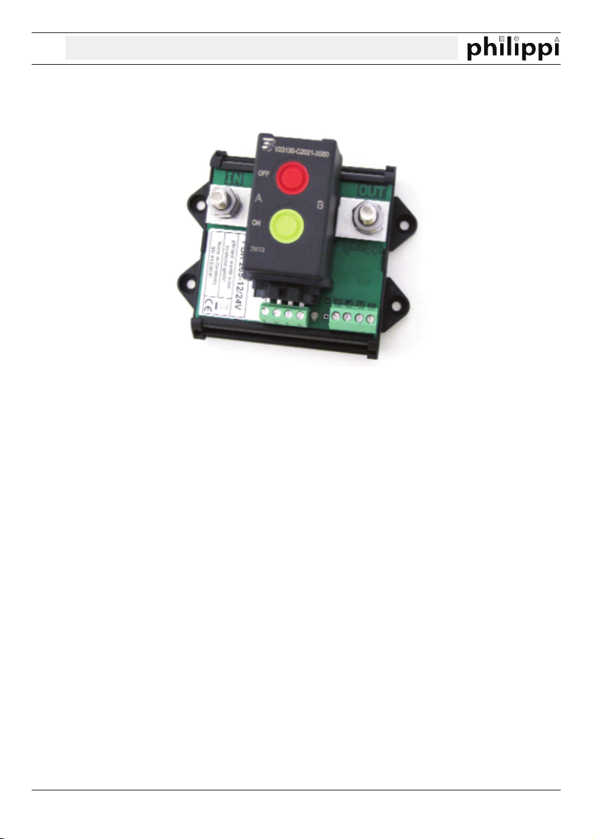
philippi VSR 200 User manual

kVSR 200
V2.2 - APR 2014
philippi elektrische systeme gmbh www.philippi-online.de
D-71686 Remseck am Neckar Telefon: +49 (0)7146/8744-0, Fax -22
USE
The VSR 200 is a voltage-dependent switching isolating relay. It is used for automatic Inter-
connection of two battery groups (e.g. starter / consumer battery or starter / bug battery)bat-
tery) in charging mode.
The VSR 200 measures the voltage of both battery groups at the connection bolts and swit-
ches them together as soon as the voltage at one of the two battery groups is above the
switch-on threshold. If the charging equipment (alternator, chargers, wind / solar) stops sup-
plying energy, the voltage drops and the relay automatically disconnects the two battery
groups as soon as the voltage falls below the switch-off threshold. In addition, the battery
banks can be disconnected during the starting process.
The VSR 200 can be activated in an emergency by manual operation at the relay or by an
optional control button to establish a connection between the battery groups in order to
select the motor from both batteries (emergency start function).
The VSR 200 is designed for continuous currents up to 200 A and has a very low self-cur-
rentconsumption.The voltage-dependent switching isolating relay VSR 200 can only be ope-
rated on DC low voltage 9 - 32V.
It is designed for use on yachts or in mobile homes and may only be used in closed rooms
that are protected from rain, humidity, dust and condensation water. Never use the voltage-
dependent switching isolating relay VSR 200 in places where there is a risk of explosion due
to gas or dust. It is not suitable for outdoor installation.
INSTRUCTION MANUAL

kVSR 200
Seite 2 V2.2 - APR 2014
WARRANTY
philippi elektrische systeme gmbh grants a two year limited and non-transferable warranty for the first
buyer of this equipment, commencing on the date of purchase and covers defects in manufacturing,
parts and materials.
Production or material defects will be corrected without costs if:
• the equipment is sent to us at the expense of the sender
• an Invoice or proof of purchase (copy) is included
• the equipment was used for its intended purpose
• no unauthorized parts were added, and the equipment was not exposed to extreme conditions
Not included in the warranty are damages from:
• overvoltage on the inputs or reverse polarity
• ingress of liquids, vapors, condensation, etc.
• lightning
Follow-up costs and normal wear and tear are not covered under warranty.
In case of warranty the defect must be clearly specified. A detailed description of the
defect will help to speed up the repair.
Please note that we cannot accept carriage forward deliveries.
EXCLUSION OF LIABILITY
Both adherence to the operating instructions, and the conditions and methods used during installation,
use and maintenance of the VSR, cannot be supervised by philippi electrical systems gmbh.
Therefore we do not take any responsibility for loss, damage or costs, which develop due to incorrect
installation and/or inappropriate use..
SAFETY REFERENCES
xunauthorized changes to the equipment will invalidate the CE sign
xthe installation of the VSR may be made only by electrical specialists.
xImportant! Pay attention to the correct polarity of the batteries!
The assembly and operating instruction is a component of the VSR package. It must be kept
(for reference). Importantly: - for later maintenance work - and for the use of subsequent owners of the
equipment.
DISPOSAL NOTE
Please take care of your local directives on waste electrical and electronic equipment. Please
use collection points for waste electrical and
electronic equipment.
SCOPE OF DELIVERY
xVSR200 Best.-Nr.: 7 0001 0120
xCover for bolts BA 2 RT(2 pcs.) Best.-Nr.: 7 0010 4012
ACCESSORIES (NOT INCLUDED IN DELIVERY)
xButton 0-1 for Emergency ON z.B. 21 x 14 mm Best.-Nr.: 5 1801 1202
(or any other push button from our assortment)
x LED without series resistor 5 mm green Best.-Nr.: 6 0005 0621

kVSR 200
V2.2 - APR 2014 Seite 3
INSTALLATION
- Mount the device close to the battery / battery bank in an easily accessible location, so that a manual
emergency operation is possible.
- The installation location should be cool and dry if possible.
- Provide strain relief for the cables (at a maximum distance of 30 cm)
CONNECTION
- The batteries must be disconnected before installation!- The wire cross section of the connecting lines
to the batteries or battery banks must must be at least 25 mm². The dissipation of the heat loss in the
relay takes place via the connected lines. Dimension the cable cross section sufficiently (page 4)!
Please remember to fuse the cable correctly near the battery!- The wire cross section of the
control lines must be at least 1 mm².
- Terminal Minus: must be connected to the minus of the on-board power supply.
- Terminal C: Connection for an (optional) button for "Battery - parallel connection" (against minus).
- Terminal L: Connection for an (optional) external control LED (against minus)
- Terminal S: Connection for "Battery disconnection" (optional) to disconnect the batteries during the start
process or during charging with a charger with several outputs or to disconnect the batteries during bow
thruster operation. This avoids high cross currents during starting as well as possible interference with
sensitive loads connected to the service battery bank.
A voltage of > 8V (via a fused line, e.g. from the ignition lock, or control line around the starter motor and
carrying voltage only during the starting procedure) separates the two battery banks.
Attention: the manual operation of the buttons directly at the relay is not recognized by the con-
trol electronics!
Control lines:
1 button
3 External LED +
(no pre resistror)
2 Minus (GND)

kVSR 200
Seite 4 V2.2 - APR 2014
OPERATION
The internal LED shows by a simple flash the readiness for operation in 12V mode. The double flashing
indicates the 24V mode. When the relay is switched on, the internal LED and the optional external LED
light up.
Signal at terminal C:
As long as the optional external button is pressed, the relay switches to EMERGENCY PARALLEL, thus
connecting both batteries. Attention: If the signal S is already present, the relay is not switched on!
Signal at terminal S:
As long as a voltage (>8V) is applied, the relay switches OFF, thus disconnecting both batteries. If the
signal C is already present, the relay will not be switched off!
TECHNICAL DATA
Rated voltage 12 V + 24 V
Operation voltage 9 - 32 V
Rated current continous 200 A / Cross section 95 mm²
Overload 5s 400 A
Peak current 0,2 s 1500 A
Switch ON- Voltage thresholds:
120 Sec 13,4 V / 26,8 V
30 Sec: 13,8 V / 27,6 V
Switch OFF- Voltage thresholds:
30 Sec: 13,0 V / 26,0 V
10 Sec :12,5 V / 25,0 V
16,0 V / 32,0 V (at Over Volatge, when C not set)
Power consumption Relais OFF: 1,5 mA @ 13 V, 3 mA @ 26 V
Relais ON: 2,5 mA @ 13 V, 5,5 mA @ 26 V
terminals M 8
Protection IP 20
Dimensions: L 111 x B 90 x H 60 mm
Recommended cable cross sections: 80 A / 25 mm² 150A / 70 mm²
100A / 35 mm² 200A / 95 mm²
120A / 50 mm²
DECLARATION OF CONFORMITY
This device fulfills the requirements of the European regulations:
2004/108/EG “ElectroMagnetic Compatibility”
Immunity EN 61000-6-1
Emission EN 61000-6-3
The conformity to this regulation is certified by the CE - sign.
This manual suits for next models
1
Table of contents
Popular Relay manuals by other brands

E.J.A. Engineering
E.J.A. Engineering Guardmaster Minotaur MSR14T installation instructions

Schweitzer Engineering Laboratories
Schweitzer Engineering Laboratories SEL-501-2 instruction manual

Schweitzer Engineering Laboratories
Schweitzer Engineering Laboratories SEL-487V manual

Pilz
Pilz PNOZ e1p operating instructions

Yokis
Yokis MD3300MRP quick start guide

Pepperl+Fuchs
Pepperl+Fuchs KFD0-RSH-1.4S.PS2 Safety manual