Zander Aachen SPEEDY ZX8T Operation manual

User Information
1
High-SPEED-Mikro-SPS SPEEDY ZX8T
L05
E61-210-00
H. ZANDER GmbH & Co. KG • Am Gut Wolf 15 • 52070 Aachen • Germany
Tel +49 (0)241 9105010 • Fax +49 (0)241 91050138 • info@zander-aachen.de • www.zander-aachen.de
English translation
Errors and technical changes reserved
against electrostatic discharge (ESD protection).
Opening the device, any manipulation of the device and
the avoidance of the safety facilities are not permitted.
All relevant safety regulations and standards must be
attended to.
Non-observance of the safety regulations may cause
death, severe injuries or substantial damage to property.
Before use, please, read the operating instructions and
keep it in a safe place. Make sure that the operating
instructions are always available for installation, initial
operation and maintenance.
SPEEDY ZX8T is the micro-PLC for maximum performance with
minimum dimensions. The heart of the control is not a micro-
controller, rather an CPLD-chip. This means that SPEEDY runs
your program internally absolutely parallel and in real-time –
with no cycle times.
SPEEDY ZX8T is used for controlling of the application flow
at machinery and equipment. It may not be used for control-
ling of safety circuits. The compliance to the relevant re-
quirements for installation and operation, especially
EN 60204-1, “Electrical equipment of machines“, is part of
the normal use.
Scope of Applica-
tions
The installation and operation must be carried out by
qualified personnel only,
who is familiar with the professional handling of machine
equipment,
who is familiar with the valid rules of industrial safety and
accident prevention,
who read and understood the operating instructions and
the system manual.
The safe function of the device during machine operation
cannot be guaranteed in case of wrong connection or
improper operation. This may lead to fatal injuries.
Pay attention to country specific regulations.
The electrical installation must be performed after discon-
necting the device and the machine from the mains sup-
ply.
The wiring must be carried out according to the instruc-
tions of this operating manual.
The person who programs the device must be protected
Due to the CPLD technology controlling without any cycle
time is provided, because all signals are operated parallelly.
So the reaction time will remain constant - regardless of the
complexity of the application.
Any problems with different cycle times and corresponding
reaction times are things of the past. No matter how fast a
packaging machine runs - the cutting will be controlled in an
accurately fitting manner and the gluing will be placed at
the right position.
For this reason SPEEDY ZX8T is the ideal controller for fast
processes at packaging machines, cutting facilities, printing
stations, bottling plants, gluing stations, plastic injection
moulding machines.
Non-observance of the instructions above will cause the
loss of warranty.
High-speed – no cycle times
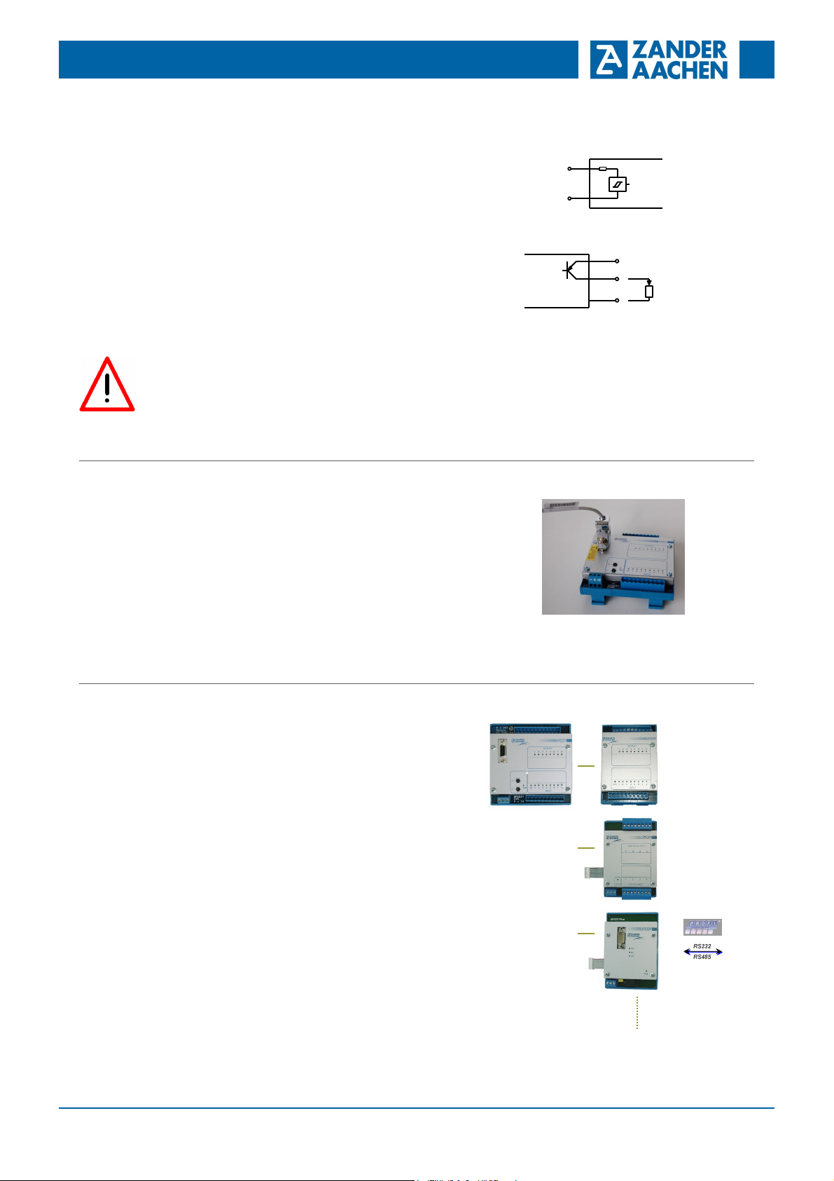
9 digital inputs
8 digital transistor outputs
1 counter input, optionally also as digital input
2 potentiometers for adjustable time functions
High interference protection, mains filter,
overvoltage protection
Simple programming
Power fail safe
Modular extension facility
Plug-in terminals
Correct Use
Features
Safety
Precautions

User Information
2
High-SPEED-Mikro-SPS SPEEDY ZX8T
L05
E61-210-00
H. ZANDER GmbH & Co. KG • Am Gut Wolf 15 • 52070 Aachen • Germany
Tel +49 (0)241 9105010 • Fax +49 (0)241 91050138 • info@zander-aachen.de • www.zander-aachen.de
English translation
Errors and technical changes reserved
Function
Installation
Fig. 3 Front View of ZX8T
Terminal Signal
L+ DC 24V Power supply
M 0V Power supply
PE Protective Earth
E1..E8 Input 1..8
CK Clock input or input 9
C 0V of Inputs, (common)
A1..A8 Output 1..8
U+, U- Power supply of the output circuit
SPEEDY ZX8T controls functions at machines and plants.
The functionality will be determined by the loaded program.
SPEEDY can be programmed easily with our PC program
EX_PRESS. The software EX_PRESS is further described
in its help system.
In addition to timer and counter functions any logical combi-
nations are programmable between inputs and outputs.
Two integrated potentiometers allow time adjustments
during running processes. Four time areas cover a range
from 100ms to 10min. Additionally division factors can be
programmed with the software. If the potentiometers are set
to the left limit you get an internal calibrated time base of
100ms.
The clock input CK can also be used as a logical digital
input, too.
Each input is switched on the hardware side with a signal
delay of approx. 100µs to ensure a high interference pro-
tection.
L+, M, PE: Power supply
Programming port
Plug-in terminal 8 outputs
Extension socket
Plug-in terminal 9 inputs
LEDs with text field
2 Potentiometers, adjustable timers
Please, read the section „Safety Precautions“ before instal-
lation and initial operation.
The operating voltage and the voltage for the digital
inputs must be generated by a power supply which com-
plies to the regulations of separated extra low voltage
(SELV).
The cable cross-sections may not exceed 2.5 mm2. Make
sure that power is turned off for installation.
A maximum cable length of the input connections of
1000 m at a cable cross-section of 0.75 mm² may not be
exceeded.
If the device does not operate after initial start, it must be
sent back to the manufacturer unopened. If the device
was opened the guarantee claim is void.
All inductive loads connected to the outputs must be
equipped with an effective protection circuit.
Please consider the information in the section “Technical
Data”
Fig. 1 Block Diagram
According to EN 60204-1 the unit is designed to be used in
switch cabinets with a minimum environmental protection of
IP54. The housing is designed to be mounted on a 35mm
DIN-rail according to DIN EN 60715 TH35.
Fig. 2 Mounting / Demounting
Electrical
Connection

User Information
3
High-SPEED-Mikro-SPS SPEEDY ZX8T
L05
E61-210-00
H. ZANDER GmbH & Co. KG • Am Gut Wolf 15 • 52070 Aachen • Germany
Tel +49 (0)241 9105010 • Fax +49 (0)241 91050138 • info@zander-aachen.de • www.zander-aachen.de
English translation
Errors and technical changes reserved
Download of a
Program
The program is created on a PC with the development
system EX_PRESS (see help system of EX_PRESS) and it
is transferred into the controller. To do this:
Connect the Programmer-USB-cable to the PC
Plug the programming cable of the programmer into the
programming interface of the controller.
Connect the operating voltage to the SPEEDY ZX8T (see
„Commissioning Procedure“).
In EX_PRESS click on “Download to EX16/ZX8T…” in
the menu “Program”
Wait until the message of the correct download appears
at the Log-Window on the PC
The inputs and outputs must be connected according to the
application/circuit diagram. Connection is made via a plug-
in screw terminal.
The switching state is indicated by LEDs at the front of the
device.
Additional information: see section „Technical Data“
Connection of the operating voltage:
+24V DC at terminal L+
0V at terminal M
Protective Earth at terminal PE
The connectors M and C may be bridged. If the terminals M
and 0V of the outputs are bridged, the ground path of the
internal power line filter will be shortened and it will become
effectless. If EMC problems occur, a mains filter (order No.
585998) may be inserted.
Caution:
If a program is loaded, SPEEDY ZX8T will immediately
execute the programmed functions after turning on the
operating voltage.
Fig. 4 Inputs / outputs
Fig 5 Download of a program
SPEEDY has got an expansion socket as a standard fea-
ture. Extension modules can be connected to this, e.g. 16
additional I/O's, analogue I/O's as well as a bus interface
module. Please, see our separate data sheets.
Extension
Modules
ANALOGUE I/O
DIGITAL I/O
Fig. 6 Extension modules
Eingänge:
E1..E8 / CK
DC 10-30V
C
0V
Inputs
Transistorausgänge:
U+
DC 10-30V
A1..A8
0V Last
500mA
Transistor outputs
load
Commissioning
Procedure

User Information
4
High-SPEED-Mikro-SPS SPEEDY ZX8T
L05
E61-210-00
H. ZANDER GmbH & Co. KG • Am Gut Wolf 15 • 52070 Aachen • Germany
Tel +49 (0)241 9105010 • Fax +49 (0)241 91050138 • info@zander-aachen.de • www.zander-aachen.de
English translation
Errors and technical changes reserved
If the fault still persists, the related device must be replaced.
The replacement of individual parts of a device is not per-
mitted.
The device does not execute any function:
Check the wiring in accordance with the connection
diagram.
Did you download the planned program?
If the fault persists, please, follow the steps which are de-
scribed in the section “Commissioning Procedure”.
Operating Voltage DC 24V, +/-20%
Residual ripple max. 5%
Current consumption approx.. 50mA plus 10mA per activated output
Inputs 8, each DC 12-30V, also as clock inputs
Clock Input 1, DC 12-30V, also as digital input
Outputs 8 transistors, PNP
Switching capacity DC 10..30V; 500mA short circuit proof
Timer 2 integrated programmable timer
Time base 100ms fixed, 0.1-2.5s; 0.3-10s ; 2-80s; 0.3-10min
variable setting via front potentiometers,
other times also possible through software
Available internal flags 44 Bit-registers, additional 1 register per output
Time Delay Input/Output approx. 100µs
Max. input frequency ca. 10kHz each input
Capacity of logical combinations approx. 5000 AND / 300 OR
LEDs Inputs, outputs, RUN
Wire width Max. 2.5mm2
Protection IP20
Temperature range 00 C to +500 C
Weight approx. 300g
Order-No. 588315 SPEEDY ZX8T, 9 inputs DC24V, 8 transistor outputs
Order-No. 588292 EX_PRESS Software for Windows 7 / XP, programmer with USB cable
Fig 7 Dimension
What to do in
Case of a Fault?
Maintenance No servicing is required. Repairs of the device are only
allowed to be made by the manufacturer.
Dimension
Drawing
Techn. Data
Variants

User Information
5
High-SPEED-Mikro-SPS SPEEDY ZX8T
L05
E61-210-00
H. ZANDER GmbH & Co. KG • Am Gut Wolf 15 • 52070 Aachen • Germany
Tel +49 (0)241 9105010 • Fax +49 (0)241 91050138 • info@zander-aachen.de • www.zander-aachen.de
English translation
Errors and technical changes reserved
Table of contents
Other Zander Aachen Relay manuals

Zander Aachen
Zander Aachen SR3C Operation manual

Zander Aachen
Zander Aachen MVisio HMI Pro User manual

Zander Aachen
Zander Aachen SR7C Operation manual

Zander Aachen
Zander Aachen SR3E User manual

Zander Aachen
Zander Aachen SR4C User manual

Zander Aachen
Zander Aachen SR3C User manual

Zander Aachen
Zander Aachen SR2C User manual

Zander Aachen
Zander Aachen SR3D Operation manual

Zander Aachen
Zander Aachen SR3D Operation manual

Zander Aachen
Zander Aachen MINOS SD1E User manual