PSA LIFESAVER 6000WIRM User manual

1
1203-7201-00
Part Number: LIF6000WIRM
Wireless Interlink and Relay Module for
LIFESAVER range of smoke alarms and
ancillary products.
This product is AC mains powered with
rechargeable battery backup.
Wireless Interlink Relay Module
Model 6000WIRM

2
Contents
1. Product Features And Specifications .................................................................................................................... 2
2. Operational Features .........................................................................................................................................................3
3. Installation Instructions.................................................................................................................................................... 4
4. Activation and RF Interlink Network .......................................................................................................................12
5. Warranty ...................................................................................................................................................................................15
1. Product Features And Specifications
•Electrical rating: 240 V AC 50Hz with 2 X 3V rechargeable battery back up
•Relay contacts rating: 240VAC/30VDC 5A.
•Low Battery : The red LED flashes once every 30 seconds.
•Multi-purpose green and red LEDs indicate the module is connected to the AC supply,
is working normally and wireless link status.
•Link button is used to interconnect wirelessly, and test.
•Wireless Radio Frequency: 918 MHz
•Wireless range of < 100 meters in open air (Line of sight)
•Wireless Interconnect: up to 24 units
•The module can be interconnected through hardwire or wirelessly
•Hardwire Interconnect Alarms: Up to any combination of 12 other non-wireless alarms.
•Operating Temperature Range: 0°C to 40°C
•Selectable relay options: (1) Smoke Alarm Latching, (2) Smoke Alarm Pulse, or (3) CO latching.
•Battery Life: At least 3 days as backup power (without alarms).
•Approved to AS/NZS 4268:2017
•Approved to AS/NZS CISPR 32:2015 AMD 1:2020
•Approved to AS/NZS 62368.1:2018

3
2. Operational Features
The Lifesaver 6000WIRM is a mains powered wireless interlink module that allows hard wired Lifesaver smoke
alarms to be connected to a wireless network. The built-in relay can be activated when smoke alarms or
devices are activated. The module is fitted with a rechargeable backup battery.
The unit is designed to be mounted on the ceiling or wall.
Wireless interconnect: up to 24 units, compatible models:
LIF6000WB, LIF6000DCW, LIF6000THL
Hardwire interconnect up to 12 units, compatible models:
LIF5800ACF, LIFCO240, LIF6000/RL, LIFHA240
The Isolation Relay provides a set of Normally Closed (NC) and Normally Open (NO) change over contacts.
This enables smoke alarms to trigger auxiliary devices such as strobe lights, sirens, bells, burglar and fire alarm
panels, activate emergency lights, shut down air conditioners or release magnetic door holders.
This isolation relay has 3 selectable modes of operation.
Select the mode of operation using the selector switch(See Figure 1).
CO Relay(CO):
•When CO relay is selected, the relay
will latch only when CO alarm is in
alarm condition.
SM latching Relay(SM-C):
•Relay stay latched or continuously
activated while smoke
and /or heat alarm in
alarm condition
SM Pulse Relay(SM-P):
•Relay activate momentarily for
2 seconds when the smoke
and /or heat alarm in alarm
condition
Selector Switch
CO
SM-C
SM-P
Figure 1
4
LED indication
There are two LED indicators. Each of them has a unique function:
This relay module has two LED indicators (Red and Green).
The LEDs indicate the following:
Green
•ON – AC Power is Present
•OFF – AC Power is not Present
Red
•LED flashes one second ON and one second OFF : Out of box, searching for network, ready to join or
create a new network.
•Two quick LED flashes every 2 seconds : CRD – Unit is set as Master
•Three quick flashes every 2 seconds: RFD – Unit is set as Slave
•LED blinks four times twice: Unit is in general reset condition and is now in stand-alone mode
•LED flashes every 2 seconds: Indicates loss of wireless interconnection.
•LED flashes every 30 seconds: Indicates low battery
3. Installation Instructions
The wireless relay module must be on a circuit breaker and
be installed in a suitable location such as the ceiling or wall.
Refer to the local building regulations and codes of
practice.
!Disconnect mains power before commencing work.
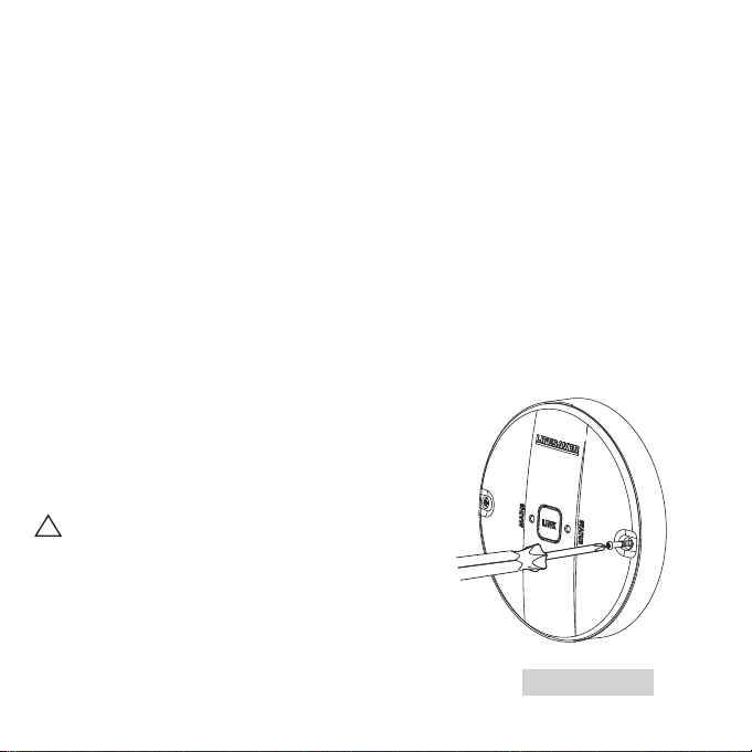
A. Remove cover (cover screws) to allow access
to wire connections. See Figure 2.
Use a small screw driver to open the cover.
Please note: The cover is clipped into place and can only
be closed in one direction.
Figure 2

5
Mark and drill two holes
for wall or ceiling anchors.
6.5mm
Wall
Expansion pipe
2.4mm 22mm
4.0mm
B. Mount base plate on proper location.
Figure 3
6
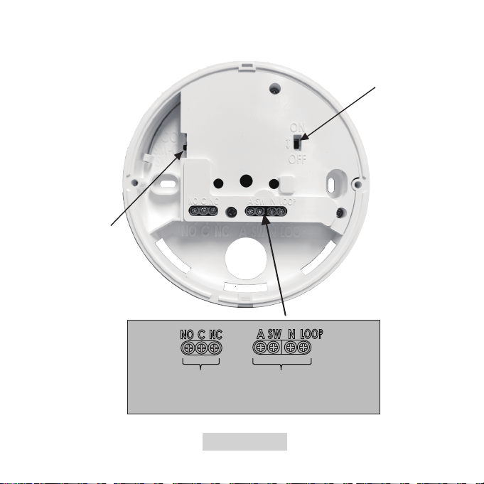
Relay Smoke/Heat/CO alarm
Terminals are classed as hazardous circuits. Tighten terminal
screws to 0.8 N.m max.
C. Wire the cables into the appropriate terminals. Then turn ON the battery switch.
Selector switch
Battery switch
Figure 4

7
C. Wire the cables into the appropriate terminals. Then turn ON the battery switch. D. After the cables are connected, re-install the module cover. See Figure 5 below.
Figure 5

8
Wiring Instructions
The wireless interlink relay module can be used for signalling compatible Lifesaver equipment or to activate
auxiliary warning devices such as external bells and sirens, hallway or stairwell lighting. It provides isolated (no
internal connection to 240 volts AC), normally open, and normally closed contacts.
!WARNING! Alarm and relay module wiring installation must comply with the current edition of AS3000
and Wiring Regulations and all appropriate prevailing local regional / national building regulations / codes of
practice.
To be installed by a qualified electrician. Failure to install this product correctly may expose the user to
electric shock or fire risk hazards. This relay module is not rated as waterproof and must not be exposed to
dripping or splashing water. The relay module must be installed correctly in order to function. The electrical
circuit used to power the alarms and the relay module must be 240 volt AC 50Hz. This relay module has a
rechargeable battery backup to allow it to function in the event of mains power outage.
!WARNING: This product cannot be operated from power derived from a square wave, modified square
wave or modified sine wave inverter. These type of inverters are sometimes used to supply power to the
structure in ‘off grid’ installations, such as solar or wind derived power sources. These power sources produce
high peak voltages that can damage the device.
!IMPORTANT: Whenever alarms and relay modules are interconnected they must be powered on a
single circuit. It is recommended to connect the module and alarms to a dedicated circuit that is separately
electrically protected. This helps minimise interference (EMI) on alarm interconnect line from CFL’s, dimmers,
LV transformers etc.
• This 6000WIRM relay module will not detect smoke or heat and must be installed in conjunction with the
specified alarms. Only connect to the specified models of smoke or heat alarm. Do not connect to any other
brand of alarm/auxilary device unless approved by PSA.
• The earth terminal connection provided is for termination purposes only and is NOT electrically connected
within the sealed alarm / base units.
WARNING: THIS WIRELESS MODULE MUST BE INSTALLED BY QUALIFIED (LICENSED)
ELECTRICIANS ONLY.
• In the interests of safety, this wireless module and all wiring must be installed by a licensed electrician in
accordance with the relevant requirements of the SAA Wiring Rules - AS3000.

9
• This wireless module can only interconnect with compatible smoke alarms. Interconnection with other
brands may cause damage, result in electric shock, fire risk and void warranty.
• It is important that the alarm be wired correctly to ensure correct operation. Incorrect wiring to the Smoke
Alarm will damage the unit and void the warranty.
• Terminals on the module are marked as follows:
WARNING: Connecting the Switch wire terminal to any other supply conductor may result in
damage to the alarm, failure to operate or shock hazard and void the warranty of the alarm.
RELAY OPERATION
The wireless relay may take a few seconds to operate when the smoke alarm or carbon monoxide alarm is
activated. This is due to the time to receive the wireless signal. Conversely, when the smoke alarm or carbon
monoxide deactivates, the relay may take a few seconds to deactivate.
MARKINGS
NO Normally Open
CCommon
NC Normally Closed
A ACTIVE
SW SWITCH WIRE (FOR INTERCONNECTION ONLY)
NNEUTRAL
LOOP DEAD TERMINAL
Relay (select settings page 3)
Smoke/Heat/CO alarm
10
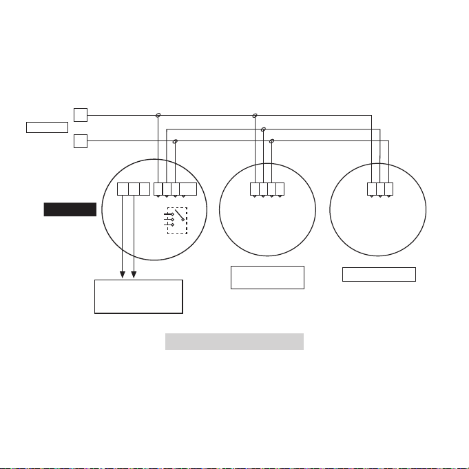
240V SUPPLY
LIF6000 SERIES
SMOKE ALARM
LIF6000WIRM
NCNO
C
To sirens, sounders,
lights and auxiliary
devices.
A
N
A S N 9A S N A S N
LOOP
CO/ HEAT ALARM
SM pulse
SWTICH
SM latching
CO
By installing the LIF6000WIRM in this manner it will allow you to operate devices such as sirens,
strobes, bells, lights, air conditioners or any devices which do not exceed 240VAC @ 5 Amps.
The wiring connecting the module with the external device is not supervised. Be sure to test the operation of
all the devices controlling the module or controlled by the module. Devices controlled by the module can be
tested by pushing the Link button on the relay and verifying that the controlled device responds in the desired
manner. Devices controlling the module can be tested by activating the device and verifying that all of the
interconnected alarms enter into alarm.
Connecting to Auxiliary Devices, see Figure 6.
Figure 6
11
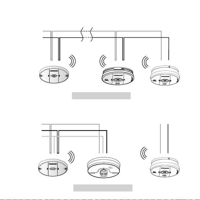
Connect all the wireless devices using only the Active & Neutral lines. Do not connect to the SW terminal.
See Figure 7 below.
To connect a hardwired device such as a heat alarm to a wireless network, install the wireless module onto the
heat alarms. See Figure 8.
Active
Active Active
Neutral
Household Cabling
Neutral
Neutral
Switch (SW)*
Household Cabling
Active
Active Active
Neutral
Household Cabling
Neutral
Neutral
Switch (SW)*
Household Cabling
Figure 7
Figure 8

12
4. Activation and RF Interlink Network
4.1 Setting Up(6000WIRM) an RF Interlink Network
For easy first time setup, we recommend unpacking all the units together on a desk or counter. Regarding
6000WIRM relay module please refer to below steps table.
User Input Detector Response Timeout
Step 1 Unpack all units and power
up the units on backup
battery.
Flash one second ON one second
OFF
Searching network
Step 2 Create a network & Join
mode (Set device as CRD).
The unit will automatically
search for other wireless
devices.
Two quick ashes every 2 seconds. Join Mode will timeout in
15 minutes
Step 3 Connect other wireless
devices and activate join
mode to create a network.
Connected devices will blink 3 times
when connected as RFD.
- Network should be open and in
join mode.
- Join Mode will timeout in 15
minutes.
Step 4 Close the network, press the
LINK button twice on cover.
All LEDs are O The unit will enter Standby Mode.

13
4.2
Adding A Device (6000WIRM) To An Existing RF Interlink Network
At some point, you might want to add another unit to your existing RF interlink network. Follow the steps in
the following table.
User Input Detector Response Timeout
Step 1 Press the LINK button twice
on any existing unit to open
the network.
Unit will respond with two quick
ashes every 2 seconds if it is the
Coordinator of the Network;
Three quick ashes every 2 seconds if
it is a RFD in the Network - Join Mode
is open.
- All devices interconnected will
turn ON LED
- Join mode will be open
- Join Mode will timeout
in 15 minutes
Step 2 Connect the 6000WIRM and
turn on the module.
Unit will ash one second ON and one
second OFF. Unit will automatically
join the network. And if successful, its
Red LED will ash three times every 2
seconds. This indicates it is congured
(as a RFD) in the network.
Join Mode will timeout
in 15 minutes after last unit joins.
Step 3 Single press. Number of blinks corresponds to
number of connected wireless
devices.
- Network should be open and in
join mode.
- Join Mode will timeout in 15
minutes.
Step 4 Close the network, press the
LINK button twice on cover.
OFF The unit was transfer to standby
mode.

14
4.3 Resetting The Wireless Connection
This section explains how to perform a general reset on a 6000WIRM unit. This restores the unit to when it was first
powered up. This procedure can also remove a 6000WIRM from a network.
Follow the steps below to resolve any of these situations:
* If you have problems connecting the 6000WIRM to a wireless network. Or if the network configuration has become
confused.
* If a 6000WIRM is consistently out of range, and needs to be removed from the wireless network.
* If you decide to transfer a 6000WIRM from your network to another wireless network (eg. at your friend’s or family’s
place).
User Input Detector Response Timeout
Step 1 Press the LINK button twice on any
existing 6000WIRM (or other wireless
smoke alarm) unit.
The unit will enter Join Mode and ash its Red LED either:
(1) Twice every 2 seconds - denotes Coordinator
(2) Three times every 2 seconds - denotes RFD
OR (3) 1 second ON, then 1 second OFF - denotes Network
Search.
Step 2 Press and hold its LINK button
for at least 4 seconds to reset the
6000WIRM unit.
The Red LED will blink four times, which is repeated, to
indicate the unit has been reset. It is now in standalone
mode, and will not be part of any network until its LINK
button is pressed twice to re-enter Join Mode.
Step 3 Press the LINK button twice on any
other wireless unit to close the Join
Mode.
Red LED on each unit will power o indicating Standby
Mode
Step 4 To re-join a network, please start
over with Section 4.2 If any issues
occur, please call PSA Technical
Support.

15
User Input Detector Response Timeout
Step 1 Press the LINK button twice on any
existing 6000WIRM (or other wireless
smoke alarm) unit.
The unit will enter Join Mode and ash its Red LED either:
(1) Twice every 2 seconds - denotes Coordinator
(2) Three times every 2 seconds - denotes RFD
OR (3) 1 second ON, then 1 second OFF - denotes Network
Search.
Step 2 Press and hold its LINK button
for at least 4 seconds to reset the
6000WIRM unit.
The Red LED will blink four times, which is repeated, to
indicate the unit has been reset. It is now in standalone
mode, and will not be part of any network until its LINK
button is pressed twice to re-enter Join Mode.
Step 3 Press the LINK button twice on any
other wireless unit to close the Join
Mode.
Red LED on each unit will power o indicating Standby
Mode
Step 4 To re-join a network, please start
over with Section 4.2 If any issues
occur, please call PSA Technical
Support.
5. Warranty and Liability
PSA Products Pty Ltd (ABN: 99 076 468 703) of 17 Millicent Street, Burwood 3125 Victoria, Australia warrants this
product for a period of 2 years from the date of purchase, as reflected on the Authorised Reseller’s or Distributor’s
invoice / receipt provided to you. PSA Products Pty Ltd will repair or replace the product (at the option of PSA
Products) due to any manufacturing defect, at the cost of PSA Products Pty Ltd (excluding any labour costs
relating to removal or re-installation of product, and transport costs).
This warranty shall not apply to the product if it has been damaged, modified, abused or altered after the date of
purchase, or if it fails to operate due to improper maintenance. To the extent permitted by law, the liability of PSA
Products Pty Ltd arising from the sale or under the terms of this limited warranty shall not in any case exceed the
cost of replacement and subject to this clause. In no case shall PSA Products Pty Ltd be liable for consequential
loss or damages resulting from the failure of the product or breach of this, or: Any other warranty, express or
implied, loss or damage caused by failure to abide by the instructions supplied in the leaflets.
To the extent permitted by law, PSA Products Pty Ltd., makes no warranty, expressed or implied, written or oral,
including that of merchantability or fitness for any particular purpose, with respect to the consumer replaceable
battery if any. This warranty is provided in addition to other rights and remedies you have under law:
Our goods come with guarantees that cannot be excluded under the Australian Consumer Law. You are entitled
to a replacement or refund for a major failure and compensation for any other reasonably foreseeable loss or
damage. You are also entitled to have the goods repaired or replaced if the goods fail to be of acceptable quality
and the failure does not amount to a major failure. What constitutes a major failure is set out in the Australian
Consumer Law.
To make a claim under warranty, take the product (with a proof of purchase) to the store where you purchased
details, proof of purchase or expense claim in writing.
Another Quality Product by:
17 Millicent Street, Burwood
Victoria 3125 Australia
Telephone: (03) 9888 9889
e-mail: [email protected]
web-site: www.psaproducts.com.au
This manual suits for next models
1
Table of contents


