manuals.online logo
Brands
  1. Home
  2. •
  3. Brands
  4. •
  5. Philips
  6. •
  7. Stereo Receiver
  8. •
  9. Philips FR965/00 User manual

Philips FR965/00 User manual

DIGITALE
A/V
SURROUND
RECEIVER
FR965,/00
envi
Ce
FR966/00s
ervice
ervice
DO[DoLBy
|
DIGITAL
TABLE
OF
CONTENTS
uv
»
io}
ce)
—_
1
OMmMPWNHHANAAKRWND
Location
Boards
/
System
info
....
Technical
Specification
.......
siete
Service
Tool
/
Measurement
setup
/
Safety...
Nae
Warning
/
Handling
Chip
components
...............
scapthenstes
staviedeele
1-
ADDreVIatiONS.
eivcccictiescaacivetledsscaucasctibeederdaccel
avi
tealedeenteass
ere
1-
INStrUCTION-FOMUSEs.....scccce.Zedeze
tap
ss
vex
ec
beceststs
deed
Muastigs
atvaesvnns
Dismantling
hints
/
Service
positionS
............c
cere
sy
caedes
3
Dismantling
hints
MDM
Module
..0........cecccceceeeeeeeteeeeeneeenereeee
3-
WITH,
GIA
GQIAIN
«a5,
convey
cos
cousceeacqactsaanexenedancnuvencavnesteevudcedetsceusancoebes
3
Block:diagra
m+.
t..5
Steck
evel
ati
cheet
IR
eee
anti
ee
eiS
Service:
Test
Program:
a:.isecs.sdiievesdecteversbeteens
Maeva
nati
aceteasiiies
Front‘Board®
«...25
Aascits
ein
nate
ase
Aide
ean
Tuner
95
diagram
Multi-Channel
Decoding
Module
.
us
Mains
Board
.........
33
9
Mono
Board
ee
e
Exploded
ViOw
sscvccisiticceetecdasbedeasstiesnssviacedepectsetenes
deplanseiectsedeas
11
Exploded
view
partslist
..............c:c::ccesscceccceesssscceceesseecseesenseneeees
12
Partslist
Mono:
Board
44.420
caine
hace
india
awit
13
7A
Safety
regulations
require
that
the
set
be
restored
to
its
original
Condition
and
that
parts
which
are
indentical
with
those
specified
be
used.
Copyright
1995
Philips
Consumer
Electronics
B.V.
Eindhoven,
The
Netherlands
All
rights
reserved.
No
part
of
this
publication
may
be
reproduced,
stored
in
a
retrieval
System
or
transmitted,
in
any
form
or
by
any
means,
electronic,
mechanical,
photocopying,
Or
otherwise
without
the
prior
permission
of
Philips.
Published
by
MD
0019
Service
Audio
Printedin
the
Netherlands
Subject
to
modification
3104
215
50070
&
PHILIPS
PCS
105
750
1-2
LOCATION
OF
PRINTED
CIRCUIT
BOARDS
P50
&
Subw.
&
#
Video
Selector
Board
Pe
oe
ee
oo
*
Sexy
Headphone
Board
VERSION
VARIATIONS
PCS
105
751
FR965
=
FR966
except
colour
FR965/00
FR966/00S
Silver
Type
&
Versions
Features
&
Board
in
used
Front
colour
SPECIFICATION
FR965/00
General
Mains
voltage
:
230V
Mains
frequency
:
50Hz
:
<
2W
at
stby
:
435x138x350
mm
:
Multibrand/Universal
Power
concumption
Dimension.
wxhxd
Remote
control
Amplifier
Output
power
Stereo
mode
(L+R)
:2x60W
DIN
(1kHz,
0,7%THD,
6Q)
Surround
mode
L+R
>
2x60W
(1kKHz,
0,7%THD,
6Q)
Center
:60W
=
(1kHz,
0,7%THD,
6Q)
Surround
Left
+
Right
:
2x60W
(1kHz,
0,7%THD,
6Q)
Distortion
(6W)
1kHz
:<0,05%
40Hz
-20kHz
:<0,2%
Headphone
:
6,38mm
stereo
jack
with
switch
Output
level
:
3V
EMF,
60Q
Crosstalk
between
source
-
1kKHz
:
<
-65dB
(1W)
250Hz
—
10kHz
:
<-60dB
Crosstalk
between
channels
-1kHz
<
-55dB
(1W)
250Hz-10kHz
:<-50dB
Frequency
response
‘$<
10Hz
—
>
30kHz
(-1dB)
:
Shortcircuit
:DC
(Vout
2
10V)
for
+1sec
:
Transformer
(
2140°
Celcius)
:
Heatsink
(
2
140°
Celcius)
Power
stage
protection
Temperature
Audio
Selector
Input
sensitivity
Phono
:5mV
impedance
47kQ/220pf
CD
:250mV
impedance
>
47kQ
CDR/TAPE
:250mV
impedance
2
47kQ
VCR
:250mV
impedance
>
47kQ
TV
:250mV_
impedance
>
47kQ
SAT
:250mV
impedance
>
47kQ
6CH/DVD
:250mV
impedance
2
47kQ
Output
level
CDR/TAPE
:250mV_
impedance
<
1kQ
VCR
:250mV_
impedance
<
1kQ
Output
level
(variable)
Subwoofer
pre-out
:800mV_
impedance
<
1kQ
Center
pre-out
:800mV_
impedance
<
1kQ
Digital
Selector
Input
:2x
cinch
:
1x
optical
Output
:1x
cinch
Video
Selector
cvss
Input
sensitivity
DVD/VCR/TV
:1Vpp
impedance
75Q
Output
level
Monitor/VCR
:1Vpp
impedance
75Q
Frequency
response
:<$50HZz
>
2=6MHz
Tone
controle
Loudness
(volume
<
-20dB
Ref:
1kHz=0dB)
:100Hz
+6dB
:10kHz
+2,5
dB
Tone
control
(Ref:
1kHz=0dB)
‘Bass
100Hz
-9dB
>+9dB
:
Treble
10kHz
-9dB
>+9cB
Multi
Channel
Decoder
-
MDM2000
MPEGS.1
/
MPEG
7.1
(7.1
downmix
to
5.1)
Dolby
Digital
(AC-3)
Digital
Theater
Systems
(DTS)
Linear
PCM
(up
to
96kHz,
24
bits
resolution)
Automatic
audio/data
type
detection
(AC-3,dts,
MPEG-2,PCM)
Dolby
Pro
Logic
MPEG-2
dual
mono
channel
selection
I/II
Virtual
Dolby
Surround
(422/423)
Virtual
MPEG
Digital
(522/523)
Virtual
Dolby
Digital
(522/523)
Virtual
DTS
Surround
(522/523)
Multi
-
Front
/
Multi
-
rear
/
Natural
Surround
Digital
Bass
Management
Parallel
Stereo
Downmix
Four
Stereo
(224)
Volume
Control!
Noise
Generator
(test
tone)
Surround
mode
selector
Delay
Center
and
Surround
Left
,
Surround
Right
Tuner-
(Tuner95)
RDS
:
Only
in
/00
FM
Tuning
range
:
87.5
—
108MHz
Grid
:
5OkHz
IF
frequency
>
10.7MHz
+25kHz
Aerial
input
>
75
Q
coaxial
Sensitivity
at
26dB
S/N
1S
2uv
Selectivity
at
300kHz
:
2
55dB
Image
rejection
:
2
100dB
Distortion
at
RF=1mV,dev.75kHz
:<0,8%
-3dB
Limiting
point
><
2pV
Crosstalk
at
RF=1mV,dev.40kHz
>
235dB
MW
Tuning
range
:
531
-
1602kHz
Grid
:
9kHz
\F
frequency
:
450kHzZ
21kHz
Aerial
input
:
Frame
aerial
Sensitivity
at
26dB
S/N
><
1,5mV/m
Selectivity
at
9kHz
:
2
230B
IF
rejection
:
2
50dB
Image
rejection
>
2
33dB
Distortion
at
RF=50mV,m=80%
133%
LW
only
in
/00
Tuning
range
:
153
-
279kHz
Grid
:
83kHz
IF
frequency
:
450kHz
+1
kHz
Aerial
input
:
Frame
aerial
Sensitivity
at
26dB
S/N
><
2,8mV/m
Selectivity
at
9kHz
:
2
26dB
{F
rejection
:
2
100dB
Image
rejection
:
2
45dB
Distortion
at
RF=50mV,m=80%
>
S$
3%dB
PCS
105
752
1-4
SERVICE
TOOL
Audio
Signals
Test Disc
1.00.0...
icceeeeeeeeseeeeee
4822
397
30184
MEASUREMENT
SETUP
Tuner
FM
Bandpass
DUT
250Hz-15kHz
LF
Voltmeter
e.g.
7122
707
48001
e.g.
PM2534
RF
Generator
e.g.
PMS5326
50Q
hh
Ri=
$/N
and
distortion
meter
eg.
Sound
Technology
ST1700B
/
1e)
ie)
Use
a
bandpass
filter
to
eliminate
hum
(50Hz,
100Hz)
and
disturbance
from
the
pilottone
(19kHz,
38kHz).
Tuner
AM
(MW,LW)
Bandpass
250Hz-15kHz
LF
Voltmeter
e.g.
7122
707
48001
e.g.
PM2534
RF
Generator
e.g.
PM5326
g
: .
prrooon
1
3/N
and
distortion
meter
i
a
{fo
os
eg.
Sound
Technology
ST1700B8
i
rd
\
if
|B)
|
|
Frame
aerial
Cry)
ed
|
@g.
7122
707
89001
(£
!
le)
fe)
:
\
t
|
i
|
pete
en
Berea
|
a
——
To
avoid
atmospheric
interference
all
AM-measurements
have
to
be
carried
out
in
a
Faraday’s
cage.
Use
a
bandpass
filter
(or
at
least
a
high
pass
filter
with
250Hz)
to
eliminate
hum
(50Hz,
100Hz).
SAFETY
SAFETY
Safety
regulations
require
that
the
set
be
restored
to
its
original
condition
and
that
parts
which
are
identical
with
those
specified
be
used.
Safety
components
are
marked
by
the
symbol
As
Veiligheidsbepalingen
vereisen,
dat
het
apparaat
in
zijn
oorspronkeliijke
toestand
wordt
teruggebracht
en
dat
onderdelen,
identiek
aan
de
gespecificeerde,
worden
to@epa
St.
De
Veiligheidsonderdelen
zijn
aangeduid
met
het
symbox
a»
Les
normes
de
sécurité
exigent
que
l
appareil
soit
remis
Le
norme
di
sicurezza
estigono
che
l’apparecchio
venga.
a
l'état
d'origine
et
que
soient
utilisées
les
piéces
de
rimesso
nelle
condizioni
originali
e
che
siano
utilizzati
j
rechange
identiques
a
celles
spécifiées.
pezzi
di
ricambiago
identici
a
quelli
specificati.
Les
composants
de
sécurité
sont
marqués
Componenty
di
sicurezza
sono
marcati
con
AY
Bei
jeder
Reparatur
sind
die
geltenden
Sicherheitsvor-
schriften
zu
beachten.
Der
Originalzustand
des
Gerates
darf
nicht
verandert
werden.
Fir
Reparaturen
sind
Original-
ersatzteile
zu
verwenden.
Sicherheitsbauteile
sind
durch
das
Symbo!
A
markiert.
PCS
105 753
}
4
|
WARNING
WARNING
All
ICs
and
many
other
semiconductors
are
susceptible
to
electrostatic
discharges
(ESD).
Careless
handling
during
repair
can
reduce
life
drastically.
When
repairing,
make
sure
that
you
are
connected
with
the
same
potential
as
the
mass
of
the
set
via
a
wristband
with
resistance.
Keep
components
and
tools
at
this
potential.
CF)
ATTENTION
Tous
les
iC
et
beaucoup
d’autres
semi-conducteurs
sont
sensibles
aux
décharges
statiques
(ESD).
Leur
longévite
pourrait
étre
considérablement
écourtée
par
le
fait
qu’aucune
précaution
nést
prise
a
leur
manipulation.
Lors
de
réparations,
s‘assurer
de
bien
étre
relié
au
méme
potentiel
que
la
masse
de
|’appareil
et
enfileer
le
bracelet
serti
d’une
résistance
de
sécurité.
Veiller
4
ce
que
les
composants
ainsi
que
les
outils
que
l'on
utilise
soient
également
a
ce
potentiel.
Potential.
ESD
74
()
WARNUNG
Alle
ICs
und
viele
andere
Halbleiter
sind
empfindlich
gegeniber
elektrostatischen
Entladungen
(ESD).
Unsorgfaitige
Behandlung
im
Reparaturfall
kann
die
Lebensdauer
drastisch
reduzieren.
Sorgen
Sie
daftir,
daB
sie
im
Reparaturfall
ber
ein
Puls-
armband
mit
Widerstand
mit
dem
Massepotential
des
Gerates
verbunden
sind.
Haiten
Sie
Bauteile
und
Hilfsmittel
ebenfalls
auf
diesem
AVAILABLE
ESD
PROTECTION
EQUIPMENT
:
anti-static
table
mat
anti-static
wristband
large
1200x650x1.25mm
small
600x650x1.25mm
connection
box
(3
press
stud
connections,
1M
)
extendible
cable
(2m,
2M
,
to
connect
wristband
to
connection
box)
connecting
cable
(3m,
2M
,
to
connect
table
mat
to
connection
box)
earth
cable
(1M
,
to
connect
any
product
to
mat
or
to
connection
box)
KIT
ESD3
(combining
all
6
prior
products
-
small
table
mat)
wristband
tester
HANDLING
CHIP
COMPONENTS
GENERAL
CHIP
COMPONENT
SOLDER
SOLDER
COPPER
TRACK
P.C.B.
GLUE
SERVIGE
PACKAGE
SOLDERING
IRON
P
COMI
NT
DISMOUNTING
MOUNTING
VACUUM
PISTON
a.g.
A
PAIR
OF
TWEEERS
4822
395
10082
IS
SOLDERING
7
IRON
A
a.g.
WELLER
solder
tip
PT-H7
A
SOLDER
@0.5-0.8mm
SOLDERING
SOLDERING
PRESSURE
1RON
IRON
SOLDER
WICK
4822
321
40042
e.g.
A
PAIR
OF
TWEEZERS
SOLDERING
TIME
SLDER
B
IS
<3
sac/side
@0!-O.8mm
>
PRESSURE
=
_
SOLDERING
H
IRON
HEATING
HEATING
B
SOLDERING
IRON
CLEANING
EXAMPLES
SOLDER
WICK
c
[Rig
oo
eae
Es
8
ee
|
CORRECT
PRECAUTIONS
SOLDERING
SRON,
CORRECT
RR
COPPER
TRACK
(QD
WAARSCHUWING
Alle
IC’s
en
vele
andere
halfgeleiders
zijn
gevoelig
voor
electrostatische
ontladingen
(ESD).
Onzorgvuldig
behandelen
tijdens
reparatie
kan
de
levensduur
drastisch
doen
vermindern.
Zorg
ervoor
dat
u
tijdens
reparatie
via
een
polsband
met
weerstand
verbonden
bent
met
hetzelfde
potentiaal
als
de
massa
van
het
apparaat.
Houd
componenten
en
hulpmiddelen
ook
op
ditzelfde
potential.
CD
AVVERTIMENTO
Tutti
iC
e
parecchi
semi-conduttori
sono
sensibili
alle
scariche
statiche
(ESD),
La
loro
longevita
potrebbe
essere
fortemente
ridatta
in
caso
di
non
osservazione
della
pil
grande
cauzione
alla
loro
manipolazione.
Durante
le
riparationi
occorre
quindi
essere
collegato
allo
stesso
potenziale
che
quello
della
massa
delapparecchio
tramite
un
braccialetto
a
resistenza.
Assicurarsi
che
i
componenti
e
anche
gi
utensili
con
quali
si
lavora
siano
anche
a
questo
potenziale.
4822
466
10953
4822
466
10958
4822
395
10223
4822
320
11307
4822
320
11305
4822
320
11306
4822
320
11308
4822
310
10671
4822
344
13999
PCoS
105
754
ABBREVIATIONS
A
ac
OVA
AC
0
Voltage
ac
10VB
AC
10
Voltage
ac
110VB
AC
110
Voitage
ac
120VB
AC
120
Voltage
ac
gnd
AC
ground
ac
hi
AC
high
voltage
1
ac
h2
AC
high
voitage
2
ac
It
AC
low
voltage
1
ac
|2
AC
low
voltage
2
acti
AC
voltage
1
ac2
AC
voltage
2
ac3
AC
voltage
3
amp
Ir
on
Amplifier
Left
-
Right
On
amp
mute
cs
amp
mute
c
s
sub
amp
mute
Ir
amp
pd
amp
prot
amp
s
on
amp
stby
av
gnd
av
|
avr
AIV
F
f1
f2
fmute
G
gndd
gnds
H
hp
gnd
hp
|
hp
on
hpr
hst
L
Isc
Is
gnd
Is
|
Is
r
M
mdm
mdm
c
out
mdm
gnd
mdm
|
dmix
mdm
|
in
mdm
|
out
mdm
r
dmix
mdm
rin
mdm
r
out
mdm
req
mdm
rst
mdm
sci
mdm
sda
mdm
sl
out
mdm
sr
out
mdm
sub
out
mfd
PCS
105
755
Amplifier
mute
center
surround
Amplifier
mute
center
surround
subwoofer
Amplifier
mute
Left
-
Right
Amplifier
power
down
Amplifier
protection
Amplifier
surround
On
Amplifier
Standby
Audio
ground
Audio
Left
Audio
Right
Audio/Video
Filament
1
Filament
2
-
Fast
mute
Ground
digital
Ground
signal
Headphone
ground
Headphone
Left
Headphone
On
Headphone
Right
Heatsink
temperature
Loudspeaker
Center
Loudspeaker
ground
Loudspeaker
Left
Loudspeaker
Right
Multi
channel
Decoding
Module
—
Center
out
—
ground
—
Downmix
Left
—
Left
in
—
Left
out
—
Downmix
Right
—
Right
in
—
Right
out
—
request
—
reset
—
!?C
clock
—
PC
data
—
surround
Left
out
—
surround
Right
out
—
subwoofer
out
Mains
failure
detection
1-6
P
p
gnd
p
p50
Ss
s
gnd
sofac
scl
sofac1
sda‘
sofac2
sda2
ss
ce
ss
clk
ss
data
surr
pre-out
T
tu
clk
tuda
tuen
tu
gnd
tul
tur
tu
rds
tu
stereo
V
v
gnd
v
scl
v
sda
Vv
sig
v
sub
sur
P50
ground
Cinema
link
P50
code
Surround
ground
Sofac
[°C
clock
Sofac
1
?C
data1
Sofac
2
IC
data2
Source
selector
chipenable
Source
selector
clock
Source
selector
data
Surround
pre-out
Tuner
clock
Tuner
data
Tuner
enable
Tuner
ground
Tuner
Left
Tuner
Right
Tuner
RDS
Tuner
stereo
Video
ground
Video
l?C
clock
Video
I?C
data
Video
signal
Video
subwoofer
surround
2-1
INSTRUCTIONS
FOR
USE
CONTROLS
[7]
POWER
/
STANDBY......Switches
the
receiver
on
and
off.
fis)
TUNER
PRESET
¢
MENU
NAVIGATOR
[2]
CINEMA
LINK................
Switches
the
system
control
bus
TUNER:
switches
to
the
next
and
between
the
receiver
and
the
TV.
previous
stored
radi¢
station.
on
and
off.
MENU:
moves
upwards
and
fal
rte
det
esau:
Sensor
for
the
infrared
remote
downwards.
control.
(i6|
<4
PREV.
/
EXIT
...............
TUNER:
searches
radio
stations.
[a4]
VIRTUAL...
Control
light
for
virtual
surround.
MENU:
switches
to
the
previous
Fe)
WALD
sea
sincmu
ct
Control
light
for
HALL.
menu
level.
Bll
Marcerirntteat
a
Display
(a7|
SETUP
MENU
................
Switches
the
menu
on
and
off.
[7]
SOURCE
SELECTOR
.....Selects
the
different
audio
and
(18)
SENS.
o-oo
nonnnn
Switches
between
lav
and
high
.
video
connectors.
ut
tuner
sensitivity.
[8]
VOLUME.
........ceccsne
Increases
and
decreases
the
[is]
NEWS/TA........-soreiven
Switches
the
ROS
news
and
volume
level.
RDS
traffic
announcement
on
[9]
FRONT
AV...
noe
Selects
the
FRONT
AV
/
GAME
and
off.
input
(FR
975
only).
(20)
TUNER
AM/FM
..............
Switches
the
wavebands
of
the
FO}
TREBLE
seen
Adjusts
the
treble
when
used
in
miner
combination
with
VOLUME.
[21]
RADIO
TEXT..................
Scrolls
through
the
cifferent
RDS
ij
BASS
oe
senne
Adjusts
the
bass
when
used
in
information.
combination
with
VOLUME.
22]
SURR.
MODE..................
Switches
through
the
different
fia]
LOUDNESS.................
Switches
LOUDNESS
on
and
off.
Speke
r
CONTOURS
-
[a]
NEXT
Po.
ccesescsceeeeeee
TUNER:
searches
radio
stations,
23
VIRT.
MODE...........
Scrolls
through
the
afferent
MENU:
switches
to
the
next
virtual
surround
soutd
modes.
menu
level.
SURROUND
ON/OFF
.....Switches
between
tle
last
fal
ENTER
/
OK..................-
Confirms
selected
menu
values.
selected
surround
mde
and
stereo.
PCS
105
701
INSTRUCTIONS
FOR
USE
REMOTE
CONTROL
Open
the
battery
compartment
of
the
remote
control
and
insert
2
alkaline
batteries,
tyoe
AA
(R06,
UM-3}.
©
PHONO
TUNER
cD
cD
Remove
batteries
if
they
are
flat
or
the
remote
control
is
not
going
Oise.
2
ectiarantn
Sa
Ko
mnt
teA
DR
ne
mati
Rn
baonboieatloh
nia
renga
=
j
to
be
used
for
a
long
time.
H
:
VCR
SAT
A
Batteries
contain
chemical
substances,
so
they
should
:
be
disposed
of
properly.
The
buttons
on
the
remote
control
work
the
same
way
as
the
corresponding
ones
on
the
receiver.
important!
You
have
to
press
a
source
button
for
longer
than
1
second
to
Switch
the
sound
source
on
the
receiver.
Pressing
a
source
et
button
for
less
than
1
second
will
only
switch
the
remote
contra!
to
use
the
commands
for
the
selected
product.
The
remote
control
remains
tuned
to
the
selected
source
until
another
source
button
on
the
remote
control
is
pressed.
This
enables
you
to
operate
additional
sources
(i.
e.
winding
a
tape)
without
changing
the
source
on
the
receiver
“St
WA
at
ant
Robe
Ere
a
Sinton
nk
acta
erat
gm
tok
tar
ie
ste
i
i
od
nd
'
j
i
|
j
|
PCS
105
702
PHONO,
TUNER,
CD,
Sinn,
ae
SSS
CINEMA
LINK
ON/OFF.
i
CHANNEL/TRACK
...
BI
CHANNEL/TRACK
...
INSTRUCTIONS
FOR
USE
Mutes
the
sound
of
the
receiver.
Switches
the
receiver
to
standby.
Switches
the
remote
control
to
the
commands
of
the
different
products.
Selects
the
sources
if
pressed
longer
than
1
second.
SAT
only
works
with
digital
satellite
receivers.
Ef
austecebsdtoheswvnnaehcetess
Keys
in
numbers
for
tracks,
stations
or
frequencies.
Numbers
consisting
of
two
figures
must
be
keyed
in
within
2
seconds.
Switches
the
system
connection
between
the
receiver
and
the
TV
on
and
off.
“aivenits
Without
function.
re
TUNER:
Switches
the
receiver
menu
on
and
off.
DVD,
TV:
Switches
the
DVD/TV
menu
on
and
off.
een
a
eerie?
Confirms
menu
options.
rs
TUNER:
Moves
in
the
menus.
Right/left
arrows
are
tuning
up/down.
CD,
CDR:
Left/right
arrows
are
searching
backwards/forwards,
up/down
arrows
are
selecting
the
nexi/previous
track.
bch
aS
acd
haces
Increases
the
receiver
volume.
Hasivecsdeiavericcseee
Decreases
the
receiver
volume.
onc
Biscss
Switches
the
functions
NEWS
and
TRAFFIC
ANNOUNCEMENT
on
and
off.
TV:
Switches
teletext
on
and
off.
SAT:
Switches
the
information
text
on
and
off.
teased
nis
Increases
the
TV
volume.
CD,
CDR,
VCR,
DVD:
Starts
playback.
Decreases
the
TV
volume.
CD,
CDR,
VCR,
DVD:
Stops
playback.
Selects
the
previous
preset
tuner
station.
VCR:
Rewinds
the
tape.
CD,
CDR,
DVD:
Selects
the
previous
track.
TV:
Selects
the
previous
channel.
Selects
the
next
preset
tuner
station.
VCR:
Fast
forwards
the
tape.
CD,
CDR,
DVD:
Selects
the
next
track.
TV:
Selects
the
next
channel.
Switches
LOUDNESS
on
and
off.
Switches
the
subwoofer
on
and
off.
SURROUND
ON/OFF
....
+/—
SUBWOOFER...
SURROUND
MODE
REMOTE
CONTROL
CDR,
VCR:
Starts
recording.
DVD:
Switches
audio
tracks.
fe
COR,
SAT,
VCR:
Clears
a
program,
cancels
selections.
DVD:
Switches
the
view
angle.
TUNER:
Switches
ta
FREQUENCY
DIRECT.
CD,
CDR,
VCR,
DVD:
Pauses
playback.
VCR:
Switches
the
index
search
on
and
off.
SAT:
Switches
the
themes
on
and
off.
DVD:
Switches
between
title
and
chapter.
CD-,
CDR-,
DVD-Changers:
Switches
to
the
next
disc.
Switches
NIGHT
MODE
on
and
off.
Scrolls
through
the
different
virtual
surround
sound
modes.
Switches
SURROUND
SOUND
on
and
off.
Increases/decreases
the
subwoofer
volume.
Increases/decreases
the
volume
of
the
rear
speakers.
While
test
tone
is
an,
the
volume
of
the
speakers
you
are
hearing
can
be
increased/decreased
with
these
buttons.
Scrolls
through
the
different
surround
modes.
Switches
the
test
tone
on
and
off.
While
test
tone
is
on,
the
volume
of
the
speakers
you
are
hearing
can
be
increased/decreased
with
+/—
REAR.
PCS
105
703
2-4
INSTRUCTIONS
FOR
USE
REMOTE
CONTROL
=
=
ee
z
Once
you
have
found
and
tested
the
codes
for
your
various
Programming
the
universal
appliances,
you
may
want
to
write
them
down
here.
You
can
identify
the
universal
remote
inscription
Multibrand/Universal.
PON
Oi
2
cees
terse
ateo
marca:
2
The
universal
remote
control
must
be
programmed
to
use
the
codes
for
your
appliances
of
different
brands.
This
is
done
by
TINE
yi
eetsatptesstedseintes
Pexeesnieicetece
keying
in
a
4-digit
code
or
by
scanning
the
codes
until
the
correct
one
is
found.
We
recommend
to
using
the
4-digit
EB
Spee
aren
Se
an
ona
ey
ere
code.
This
methad
is
faster
and
more
reliable.
The
code
scanning
method
should
only
be
used
if
you
cannot
find
the
CORT
ARE
cc
esdateieesiseataec
abies
code
for
one
of
your
appliances.
The
code
table
can
be
found
at
the
end
of
the
booklet.
AN
cece
Acsicinsaan
Weta
tesiteatatapoire’lales
ct
22
Important!
WG
ape
iees
teeuare
net.
The
buttons
of
the
remote
control
must
be
used
for
programming,
not
the
buttons
of
the
receiver
or
other
A
Aces
ccetenek
testa
Oe
hacen
ak
he
appliances.
DV
Bi
hal
encase
een
indhe
ne
eateaeiede
Programming
with
the
4-digit
code
1
Keep
the
source
button
for
the
appliance
which
should
be
Resetting
the
remote
control
controlled
and(!)
pressed
for
3
seconds,
1
Keep
one
of
the
source
buttons
and
C
pressed
for
3
seconds.
2
Key
in
the
4-digit
code
for
the
appliance
(codetable
at
the
end
of
the
booklet).
2
Key
in
the
3-digit
code
981.
-»The
remote
control
is
now
reset
to
all
its
original
Philips
Notes:
—/f
more
than
4
digits
are
entered,
the
remote
codes.
control
will
recognize
only
the
ones
keyed
in
first.
—
If
you
do
not
key
in
a
code
within
30
seconds
the
remote
control
will
switch
off
the
programming
function
without
changing
the
code.
~
To
program
a
new
appliance,
simply
overwrite
the
old
code
by
entering
a
new
one.
Scanning
the
codetable
1
Switch
on
the
appliance
which
should
be
controlled.
2
Keep
the
source
button
for
the
appliance
which
should
be
controlled
and()
pressed
for
3
seconds.
3
Press
and
release
(4
again.
-»The
remote
control
sends
the
codes
for
channel
up
or
standby
(depending
on
the
selected
source}
for
one
brand
after
the
other.
4
As
soon
as
the
appliance
reacts
—
switches
to
the
next
channel
or
to
standby
~
press
()
to
confirm
the
cade.
~»
The
identified
code
will
be
used.
*
If
the
set
does
not
react
within
2
minutes,
the
code
for
this
appliance
is
not
stored
in
the
remote
control.
The
code
of
the
remote
control
will
remain
unchanged.
Note:
When
taking
out
the
batteries
of
the
remote
control
for
more
than
1
minute
the
codes
must
be
reprogrammed.
|
PCS
105 704
INSTRUCTIONS
FOR
USE
wi
=
S
et
a
\o_\
\
ee
AOOLEA
sean
GOV)
AAG
1
@E
CAG
8
aa
ag
a
As
ete
o..
_——
CONNECTORS
Connect
to:
Aheadphone
with
a6.3mm
plug.
Left
and
right
audio
out
sockets
of
appliances
such
as
video
cameras
and
game
consoles.
Video
out
sockets
of
appliances
such
as
video
cameras
and
game
consoles.
Right
and
left
front
speaker.
Center
speaker.
Right
and
left
surround
speaker.
Connectors
Connectors
name
6.3
mm
headphone
socket
[1]
PHONES
at
the
front
Audio
and
video
inputs
[2]
FRONT
AV
/
GAME
at
the
front
(FR
975
only)
FRONT
AV
/
GAME
FRONT
SPEAKERS
R,L
CENTER
SURROUND
SPEAKERS
RL
AUDIO
IN/OUT
CDR/TAPE
OUT
6
CHANNEL
/
DVD
INPUT
DIGITAL
AUDIO
IN/OUT
CDR/TAPE
IN
CD
IN
SAT
IN
SNS)
|S)
|B)
S)
|e}
leo]
|olle
f=
}o]
[21]
PHONO
GND
~
VIDEO
IN/OUT
Antenna
connectors
Preamplified
outputs
ft7|
COAX
TIN
fis)
COAX
2
IN
"jg
COAX
OUT
20
OPTICAL
IN
[2o)
OPTICAL
1
(2)
IN
py
(23)
S-VIDEO
DVD
IN
2a]
MON
OUT
aq
VCR
IN
faa]
VCR
OUT
9]
SAT
IN
Input
of
a
CD
recorder
or
a
tape
deck.
Output
of
a
CD
recorder
or
a
tape
deck.
Output
of
a
CD
player.
Output
of
a
satellite
system.
VCR
OUT
Input
of
a
video
recorder.
VCR
IN
Output
of
a
video
recorder.
TVIN
Output
of
a
TV.
15|
PHONO
IN
Output
of
a
turntable
with
MM
coil.
Ground
cable
of
a
turntable.
(16|
6
CHANNEL
/
DVD
INPUTS
channel
output
of
appliances
such
as
DVD
or
laserdisc
players.
Coaxial
output
of
digital
appliances
(default
input
for
source
DVD}.
Coaxial
output
of
digital
appliances.
Coaxial
input
of
digital
appliances
such
as
CD
recorders
or
MD
recorders.
Optical
output
of
digital
appliances
such
as
DVD
players,
CDplayers,
CD
recorders
or
MOD
players
(FR
965
only).
Optical
output
of
digital
appliances
such
as
DVD
players,
CDplayers,
CD
recorders
or
MD
players
(FR
975
only).
(a5)
AM
LOOP
2g
FIM
75
Q
"7
CENTER
PRE-OUT
S-Video
inputs/outputs
of
video
appliances
for
better
video
quality
(FR
975
only).
Output
of
a
DVD
player.
Input
of
a
monitor
(e.
g.
the
TV}.
Output
of
a
video
recorder.
Input
of
a
video
recorder
(for
recording).
Output
of
a
satellite
system.
Frame
antenna
supplied.
Wire
antenna
supplied
or
exterior
antenna.
Input
of
a
TV
when
it
is
used
as
the
centre
speaker
(only
posi
ble
when
the
CINEMA
LINK
system
bus
is
connected).
Input
of
a
powered
subwoofer.
System
control
bus
sockets
of
a
Philips
TV
with
CINEMA
LIN(.
Supplies
same
voltage
as
mains.
Up
to
100
W
total
permitte(
load.
(30
SUBWOOFER
PRE-OUT
System
control
bus
[37]
CINEMA
LINK
Mains
outlets
[32]
AC
OUTLET
(not
on
all
versions}
Mains
lead
{33}
After
all
other
connections
have
been
made,
connect
th:
mains
lead
to
the
wall
socket.
PCS
105
705
INSTRUCTIONS
FOR
USE
CONNECTIONS
There
are
analogue
and
digital
connectors
available
on
some
appliances.
If
possible
use
the
digital
connection;
usually
this
will
result
in
better
sound
quality.
See
“Reassigning
a
source
selection”
on
how
to
use
the
digital
connectors
of
the
receiver.
Because
of
a
different
kind
of
output
signal,
the
use
of
Dolby
Digital
Laserdisc
requires
an
optional
AC-3
RF
demodulator.
POWERED
SUBWOOFER
MONITOR
/
TV
AUDIO
OUT
wea,
ai
y
A(T
LNG
,
]
i
CAUTION
(0)
fe][s]
g—-oj-0f7
(0)
9
28
OVO
PLAYER
PCS
105
706
2-7
7NSTRUCTIONS
FOR
USE
CONNECTIONS
lf
the
receiver
and
your
Philips
TV
{or
even
better
in
addition
a
Philips
VCR
or
DVD
player}
with
Cinemalink
are
connected
with
the
CINEMA
LINK
system
bus
contral,
some
extra
system
benefits
are
offered:
—
Upon
starting
a
source,
the
system
will
automatically
switch
to
that
input.
—
You
may
contral
the
system
via
the
TV
screen.
Depending
on
the
language
of
the
TV,
this
can
be
done
in
your
preferred
language.
—
The
TV
can
function
as
the
center
speaker
of
your
system,
making
a
separate
center
speaker
unnecessary.
(The
cable
@)
has
to
be
purchased
separately.)
~
By
pressing
the
standby
button
on
the
remote
control,
you
can
switch
the
complete
system
to
standby.
MMMM
DVD
PLAYER
a
r
©
(eile)
2
$2330
jo
€
CAUTION
RUSK
OF
ELECTRIC
SHOCK
DD
NOT
OPEN
VCR
VIDEO
OUT
VIDECIN
FCS
105
707
2-8
INSTRUCTIONS
FOR
USE
The
type
plate
iz
located
on
the
rear
of
the
receiver.
1
Check
whether
the
mains
voltage
as
shown
on
the
type
plate
corresponds
to
your
local
mains
voltage.
If
it
does
not,
consult
your
dealer
or
service
organization.
2
Connect
the
mains
cable
to
the
wai!
socket.
To
disconnect
the
set
from
the
mains
completely,
remove
the
mains
plug
from
the
wall
socket.
For
users
in
the
U.
K.:
please
follow
the
instructions
on
page
2.
Some
of
the
speaker
connections
on
the
receiver
are
screw
connectors
and
some
are
click-fit
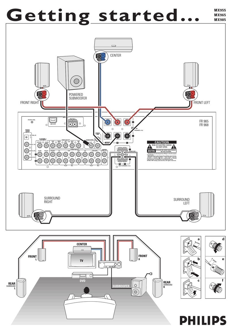
connectors.
Use
them
as
shown
below.
1
Always
connect
the
coloured
{or
marked)
wire
to
the
coloured
terminal
and
the
black
(or
unmarked)
wire
to
the
black
terminal.
N
Connect:
~
Left
front
speaker
to
L
(red
and
black)
—
Right
front
speaker
to
R
(red
and
black}
~
Center
speaker
to
CENTER
(blue
and
black)
—
Left
surround
speaker
to
SURROUND
L
(grey
and
black)
~
Right
surround
speaker
to
SURROUND
R
(grey
and
black)
You
may
use
your
Philips
TV
with
CINEMA
LINK
as
the
center
speaker.
For
TVs
with
a
scart
connector
an
additional
audio
cinch-to-scart
cable
is
needed.
For
TV's
with
cinch
connectors
additional
cinch
cables
are
needed.
These
cables
must
be
connected
to
the
blue
CENTER
PRE-OUT
connector
on
the
back.
Look
into
the
instruction
manual
of
your
TV
on
how
to
use
it
as
the
center
speaker.
PCS
105
708
CONNECTIONS
—
‘
AM
(MW)
antenna
The
loop
antenna
supplied
is
for
indoor
use
only.
Position
the
antenna
as
far
away
as
possible
from
the
receiver,
the
TV,
the
cables,
a
DVD
player,
a
VCR
and
other
radiation
sources.
1
Fit
the
plug
of
the
frame
antenna
to
AM
LOOP
as
shown
below.
2
Turn
the
antenna
for
optimum
reception.
ae
ANTENNA
————~
es
=
|
Ea
FM
antenna
The
wire
antenna
supplied
can
only
be
used
to
receive
nearby
stations.
For
better
reception
we
recommend
using
a
cable
antenna
system
or
an
outdoor
antenna.
1
Fit
the
supplied
wire
antenna
to
FM
75
Q
as
shown
below.
2
Move
the
antenna
in
different
positions
for
optimum
reception.
¢
|f
you
are
using
a
cable
antenna
system
or
an
outdoor
antenna,
fit
the
antenna
plug
to
FM
75
Q
instead
of
the
wire
antenna.
°
To
remove
the
FRONT
AV
/
GAME
cap,
press
on
the
right
side
of
the
cap.
©
Insert
the
cap
from
below
to
close
the
compartment.
pe
ae
ST
ra
INSTRUCTIONS
FOR
USE
aS
CENTER
SURROUND
(REAR) (REAR)
LEFT
RIGHT
General
hints
for
positioning
Avoid
positioning
the
speakers
in
a
corner
or
on
the
floor
as
this
will
boost
the
bass
tones
too
much.
Placing
the
speakers
behind
curtains,
furniture,
etc.
will
reduce
the
treble
response.
The
listener
should
always
be
able
to
“see”
the
speakers.
Each
room
has
different
acoustic
characteristics
and
the
positioning
possibilities
are
often
limited.
You
can
find
the
best
position
for
your
speakers
by
referring
to
the
picture
above.
As
a
minimum
we
recommend
5
speakers
(2
front,
a
center,
2
surround)
for
good
surround
sound.
It
is
possible
to
reproduce
some
kind
of
surround
sound
with
fewer
speakers.
This
is
done
by
redirecting
the
signals
which
are
foreseen
for
the
missing
speakers
to
the
existing
ones.
See
“Menus”
on
how
to
set
up
the
receiver
correctly
for
the
number
and
size
of
the
speakers
used.
Positioning
the
front
speakers
The
front
speakers
should
be
placed
right
and
left
in
front
of
the
listening
position
like
usual
stereo
speakers.
Positioning
the
center
speaker
The
center
speaker
should
be
placed
in
the
center
between
the
two
front
speakers,
e.
g.
underneath
or
on
top
of
the
TV.
The
best
height
for
the
center
speaker
is
the
height
of
the
listener's
ears
(while
seated).
Positioning
the
surround
speakers
The
surround
speakers
should
face
each
other
and
be
in
line
with,
or
slightly
behind
the
listener.
Positioning
the
subwoofer
A
subwoofer
can
be
used
to
enhance
the
bass
performance
of
your
system
dramatically.
The
subwoofer
can
be
positioned
anywhere
in
the
room,
because
it
is
not
possible
to
locate
the
source
of
deep
tones.
Nevertheless,
you
should
not
place
the
subwoofer
in
the
middle
of
a
room,
since
the
bass
could
be
severely
weakened.
Do
not
place
any
object
on
the
subwoofer.
SYSTEM
SETUP
The
relative
volume
of
the
speakers
must
be
adjusted
for
optimal
surround
sound.
You
should
be
at
yous
ust!
!siseing
position
when
adjusting
the
speaker
volume.
See
“Receiver
menus”
on
how
to
set
up
the
receiver
for
the
used
speakers.
Ideally,
the
volume
in
the
listening
position
should
be
the
same
from
all
speakers.
1
Press
POWER
/
STANDBY
to
switch
on
the
receiver.
“2
Press
TEST
TONE
on
the
remote
control.
—»
A
test
tone
coming
from
the
different
speakers,
except
the
subwoofer,
is
heard.
3
Press
+/—
REAR
on
the
remote
control
to
increase/decrease
the
volume
of
the
actual
speaker.
The
best
result
is
achieved
when
all
speakers
have
equal
volume
in
the
listening
position.
4
Press
TEST
TONE
on
the
remote
control.
—»
The
test
tone
stops.
Note:
If
you
are
not
completely
satisfied
with
the
volume
settings,
we
recommend
making
minor
adjustments
to
them
during
surround
sound
playback.
If
the
receiver
is
used
at
very
high
power
it
can
produce
distortions
which
may
seriously
damage
your
speakers.
If
distortions
occur,
reduce
the
volume
and
the
tone
controls
to
a
level
where
the
sound
is
acceptable
again.
To
avoid
overheating
of
the
set
a
safety
circuit
has
been
built
in.
Therefore
your
set
may
disconnect
under
extreme
conditions.
If
this
happens,
switch
the
set
off
and
let
it
cool
down
before
reusing
it.
Connecting
headphones
to
PHONES
will
switch
off
the
speakers.
The
receiver
switches
to
STERED
and
surround
sound
will
be
reduced
to
a
stereo
signal
which
is
reproducible
by
standard
headphones.
Disconnecting
the
headphones
switches
on
the
speakers
again.
If
you
wish
to
enjoy
surround
sound
again,
switch
the
receiver
back
to
surround
sound.
Clean
the
receiver
with
a
soft,
slightly
dampened,
lint-free
cloth.
Do
not
use
any
cleaning
agents
as
they
may
have
a
corrosive
effect.
Do
not
expose
the
receiver
to
humidity,
rain,
sand
or
excessive
heat
(caused
by
heating
equipment
or
direct
sunlight).
PCS
105
709
2-10
INSTRUCTIONS
FOR
USE
The
diplay
ol
of
the
receiver
is
divided
into
4
sections,
sich
are
to
be
used
for
the
following:
Speaker
diagram
A
rectangle
with
a
letter
in
it
shows
that
a
speaker
has
been
selected
in
the
setup
menu.
However,
the
subwoofer
indicator
will
only
light
when
a
subwoofer
signal
is
available.
If
only
a
letter
is
shown,
this
speaker
is
not
used
and
its
sound
is
reproduced
by
the
other
speakers.
a)
(@
__...
virtual
surround
sound
SURROUND.................
surround
sound
is
reproduced
DIGITAL
SURROUND
....digital
surround
sound
is
reproduced
LE.
Relcciweigedetse
front
left
and
right
speaker
Cie
teninahes
center
speaker
SL)
SR
eeudestiae
surround
speakers
SWS
heeft
subwoofer
Menu
indication
These
signs
show
you
if
the
menu
is
on
or
off
and
indicate
in
which
direction
you
may
move.
MOEMU
oe.
ececseesceseee
menu
is
on
an
I
You
may
move
backwards
to
the
previous
menu
topic
using
<4
PREV.
/
EXIT
{“left”
key
on
the
remote
control).
Bee
aunsaded
You
may
move
up
in
an
option
list
using
#
MENU
NAVIGATOR
("up”
key
on
the
remote
control).
Woidiisesiaty,
Gilet
You
may
move
down
in
an
option
list
using
4
MENU
NAVIGATOR
(“down”
key
on
the
remote
control).
Peas
You
may
move
forward
to
the
next
menu
topic
using
NEXT
>
(“right”
key
on
the
remote
control).
DKS
ces
eigenen.
You
may
confirm
the
displayed
value.
PCS
105
710
DISPLAY
Status
lights
Signs
showing
you
various
settings
and
information
about
the
status
of
the
receiver.
1
Tuner
is
tuned
to
a
preset
radio
station.
SENS
HI...
Tuner
is
switched
to
high
sensitivity.
SENS
LO...
Tuner
is
switched
to
low
sensitivity.
CINEMA
LINK
ON
......CINEMA
LINK
is
active
STEREO...
.sccesseseees
An
FM
station
is
being
received
in
stereo.
An
RDS
station
is
being
received.
...An
RDS
station
with
EON
is
being
received.
HALL
effect
is
on.
RDS
traffic
announcement
is
on
RDS
news
announcement
is
on
Analogue
input
is
being
used
for
the
playing
source.
WUGHT
ose
ceeeeeeeaes
NIGHT
MODE
is
on.
COAX
Vo.
ccecccsseeee
Coaxial
digital
input
COAX
1
is
being
used
for
the
playing
source.
Coaxial
digital
input
COAX
2
is
being
used
for
the
playing
source.
Incoming
multi
channel
signals
are
being
reduced
to
fewer
output
signals
(depending
on
the
number
of
speakers).
OPT
etiaeds
Optical
digital
input
OPTICAL
IN
is
being
used
for
the
playing
source
(FR
965
only}.
ORT
1
neha
eae
Optical
digital
input
OPTICAL
1
IN
is
being
used
for
the
playing
source
(FR
975
only).
OPT
26
escrnslen
dn
Optical
digital
input
OPTICAL
2
IN
is
being
used
for
the
playing
source
{FR
975
only).
LOUDNESS
.................
LOUDNESS
is
switched
on.
Information
area
A
NA
IA
A
ay
1M
UN
LAN
AN
i
4
ANA
NAN
4
I
|
DH
i
G4
Oe
Ne
AM
This
area
is
used
for
feedback
of
the
receiver,
tuner
frequencies,
menu
options,
values
and
scrolling
text
messages.
INSTRUCTIONS
FOR
USE
k
The
receiver
is
equipped
with
a
menu
system.
The
menu
is
used
for
the
setup
of
the
receiver.
The
different
menu
options
are
related
to
each
other
in
a
logical
way.
Let's
assume
you
have
no
center
speaker
connected,
and
therefore
switched
CENTER
SPEAKR
toNZ.
Ifyou
try
touseVOL
CENTER,
a
message
will
be
scrolled
that
this
is
not
possible
INSTALL
CENTER
SPEAKER}.
The
menu
always
works
the
same
way.
Arrows
in
the
display
show
you
the
possible
moving
directions.
1
Press
SETUP
MENU.
—»>MENU,
and
*
EFFECTS
is
displayed.
¢
You
can
exit
the
menu
at
any
time
by
pressing
SETUP
MENU.
2
Turn
&
MENU
NAVIGATOR
until
the
desired
option
(or
a
value)
is
displayed.
3
Press
NEXT
>
to
choose
the
displayed
option
(or
ENTER
/
OK
to
confirm
a
value).
e
You
can
leave
any
option
(values
remain
unchanged)
by
pressing
<4
PREV.
/
EXIT.
Menu
structure
*
EFFECTS
Switches
sound
effects.
VIRT SURR
virtual
surround:
0...100
%
VOL
BRLANCE
Adjusts
the
relative
volume
balance
between
the
connected
speakers.
nm
—
TEST
TON
Test
tone:
on/off
I—
OL
FRONT
=L
Volume
front
left
speaker:
~50...+50
VOL
FRONT-R
Volume
front
right
speaker:
—50...+50
t—
OL
CENTER
Volume
center
speaker:
—50...+50
aK
—VOL
REAR-L
Volume
rear
left
speaker:
—50...+50
L—j/OL
RERR-R
Volume
rear
right
speaker:
-50...+50
.
LOL
SUBWOOFER
Volume
subwoofer:
—50...+50
2-11
MENUS
Note:
When
using
the
6
CHANNEL
/
DVD
INPUT
the
values
k
>
ae
below
cannot
be
changed.
SPEAKR
SETU
Selects
the
used
speakers.
SUBW
PRESENT
Subwoofer
present:
yes/no
CENTER
SPERKR
Center
speaker
present:
yes/no
REAR
SPERKER
Rear
speakers
present:
yes/no
STFES
SPERKR
STZ
Chooses
the
speaker
sizes
of
the
used
speakers,
for
optimal
sound
reproduction.
LARGE
indicates
a
speaker
which
can
reproduce
frequencies
lower
than
50
Hz.
If
SUB
PRESENT
is
setto
NG,
FRONT
STZE
can
only
be
settoLARGE.IfFRONT
SIZE
is
set
toSMALL,
CENTER
SIZE
can
only
be
set
to
SMALL
and
consequently
a
subwoofer
must
be
connected.
L—FRONT
STZ
Left
and
right
front
speakers:
small/large
LC
ENTER
STZ
Center
speaker:
small/large
L—
REAR
SIZE
ole
Rear
speakers:
small/large
SPK
DISTANCE
Distance
between
the
usual
listening
position
andthe
speakers.
This
defines
the
delay
time
for
the
surround
sound.
L—
DISTANCE
L/P
Distance
to
front
speakers:
1...10
m
HK
TISTANCE
CNT
Distance
to
center
speaker:
1...10
m
L_ISTANCE
REAR
Distance
to
rear
speakers:
1...10
m
PCS
105
711
INSTRUCTIONS
FOR
USE
®
SELECT
INPUT
Assigns
the
audio
input
connectors
to
the
different
source
selections
chosen
with
SOURCE
SELECTOR
(see
“SOURCE
SELECTION”
for
details).
r—
CORK
|
igital
coaxial
input
1,
COAX
1
IN
OAK
igital
coaxial
input
2,
COAX
2
IN
PT
(FR
965
only)
igital
optical
input,
OPTICAL
IN
PT
|
{FR
975
only)
igital
optical
input,
OPTICAL
1
IN
PT
©
(FR
975
only)
Digital
optical
input,
OPTICAL
2
IN
t—
SAT
IN
Analogue
audio
input
SAT
IN
Ver TRI
a
pg
Analogue
audio
input
VCR
IN
Tie
The
eo
|
|
moovooaons
=
Analogue
audio
input
TV
IN
COR
IN
Analogue
audio
input
CDR
IN
CT
IN
Analogue
audio
input
CD
IN
&
CH
IN
Analogue
audio
input
6
CHANNEL
/
DVD
INPUT
*
TUNER
Setup
for
preset
radio
stations
(see
“TUNER”
for
details).
AUTO
INSTALL
Stores
radio
stations
automatically
MAN
INSTALL
Stores
radio
stations
manually
IVE
NAM
Allows
to
assign
names
to
stored
radio
stations
RESHUFFLE
Resorts
stored
radio
stations
.PCS
105
712
2-12
MENUS
If
the
receiver
is
connected
to
a
Philips
CINEMA
LINK
TV
via
the
CINEMA
LINK
system
control
bus
sockets
(see
“CONNECTIONS"),
you
may
use
the
TV
to
set
up
the
system.
An
option
called
RECEIVER
will
be
added
to
the
TV
menu.
If
CINEMA
LINK
is
on,
adjustments
on
the
receiver
will
be
shown
on
the
TV
screen
for
a
few
seconds.
Consult
the
instruction
booklet
of
your
TV
on
how
to
use
the
TV
menu.
The
options
offered
may
vary
by
TV
madel.
Switching
the
connection
©
Press
CINEMA
LINK
to
switch
the
connection
between
the
receiver
and
the
TV
either
on
or
off.
-»|f
the
connection
is
switched
on,
CINEMA
LINK
ON
is
displayed.
Note:
We
recommend
switching
CINEMA
LINK
off
during
recording.
This
avoids
unwanted
interruptions
due
to
switching
TV
functions.
Hf
CINEMA
LINK
is
switched
on
and
the
TV
menu
is
active,
TY
MENU
is
displayed
and
the
menu
and
sound
functions
on
the
receiver
are
locked.
INSTRUCTIONS
FOR
USE
When
selecting
a
source
by
turning
SOURCE
SELECTOR,
the
audio
and
video
inputs
with
the
corresponding
name
are
activated.
The
incoming
signal
is
reproduced
by
all
audio
and
~
if
the
source
includes
a
video
signal
—
video
outputs
of
the
receiver.
It
is
possible
to
reassign
a
source
selection
to
other
than
these
standard
inputs.
Source
selected........Connectors
used
DVD
ivanceadetnets
COAX
1
digital
audio
input
and
DVD
IN
video
input
PHONO...
escesseseceseees
PHONO
IN
audio
input
TUNER
sex
caiacs
eolscsdescrseceeee
The
tuner
part
of
the
receiver
is
used,
all
inputs
are
switched
off.
CD
IN
audio
input
CDR/TAPE
IN
audio
input
TV
IN
audio
input
and
no
video
input
WOR
iaisk.
caactiaceottateoterttons
VCR
IN
audio
input
and
VCR
IN
video
input
SAM
Acigsatsteldaurise
SAT
IN
audio
input
and
SAT
IN
video
input
6
any
of
the
available
sources
(excluding
TUNER
and
PHONO).
The
assignment
can
be
done
viathe
¥
SELECT
INPUT
option
in
the
menu.
See
below
for
more
details.
If
a
source
is
selected
with
SOURCE
SELECTOR
the
standard
audio
input
is
used.
To
change
this,
the
source
selection
must
be
reassigned
to
another
audio
input.
Example:
Reassigning
C2
from
the
analogue
CD
IN
audio
input
to
the
digital
COAX
2
IN
audio
input.
1
Choose
¥
SELECT
INPUT
from
the
menu
and
press
NEXT
>.
2
Turn
SOURCE
SELECTOR
to
select
the
source
which
should
be
reassigned
{e.
g.
£3}.
—»The
name
of
the
source
is
displayed
and
the
light
of
the
source
flashes.
3
Turn
4
MENU
NAVIGATOR
to
select
the
input
connectors
which
should
be
used
(e.g.CD
-)
COAX
2).
4
Press
ENTER
/
OK
to
confirm
your
selection.
—»5TORET
is
displayed
briefly.
§
This
source
selection
is
now
using
the
chosen
audio
input
(e.
g.
£5
uses
the
COAX
2
IN
input
connectors,
coax
2
lights
when
switching
to
CD).
The
6
CHANNEL
/
DVD
INPUT
connectors
can
be
assigned
to
|
2-13
SOURCE
SELECTION
appliances
_
-
You
may
assign
more
than
one
source
to
a
source
selection.
This
can
be
useful
when
products
are
connected
one
after
the
other
in
a
chain.
Example:
A
VCR
is
connected
to
the
TV
but
only
the
TV
is
connected
to
the
receiver.
Both
SOURCE
SELECTOR
settings,
TV
as
well
as
VCR,
have
to
use
the
TV
input
connectors.
1
Choose
¥
SELECT
INPUT
from
the
menu
and
press
NEXT
>.
2
Turn
SOURCE
SELECTOR
to
select
the
source
which
should
be
reassigned
(e.
g.
CF).
—»The
name
of
the
source
is
displayed
and
the
light
of
the
source
flashes.
3
Turn
¢
MENU
NAVIGATOR
to
select
the
input
connectors
which
should
be
used
(e.g./CFR
-)
Ti
IN),
4
Press
ENTER
/
OK
to
confirm
your
selection.
—-»STORED
is
displayed
briefly.
5
This
source
selection
is
now
using
the
chosen
audio
input
(e.
g.
CF
uses
the
TVIN
input
connectors,
}’CR
<Ti
IN}
is
displayed
briefly
when
switching
to
VCR).
HAN
The
6
CHANNEL
/
DVD
INPUT
can
be
used
to
connect
a
device
with
a
built-in
multichannel
decoder
(e.g.
Doby
Digital,
DTS,
etc.)
and
6-channel
output
connector,
i.
e.
a
high
end
DVD
player.
When
using
the
6
CHANNEL
/
DVD
INPUT
audio
input,
the
receiver
works
as
a
multichannel
amplifier.
The
source
reproduces
surround
sound
and
sends
it
to
the
rece
ver
divided
into
the
necessary
channels. Therefore
the
SURROUND
ON/OFF,
HALL
and
SURR.
MODE
buttonhave
no
effect
since
the
provided
signal
is
already
multichamel.
From
a
source
which
is
connected
to
the
6
CHANNEL
/
DVD
INPUT
audio
input
cannot
be
recorded.
PCS
105
713
|
|
|
:
{
|
a
4
|
INSTRUCTIONS
FOR
USE
Press
POWER
/
STANDBY
to
switch
on
the
receiver.
2
Turn
SOURCE
SELECTOR
to
select
a
source.
~»The
name
of
the
source
is
displayed.
©
You
can
select
the
FRONT
AV
/
GAME
input
by
pressing
FRONT
AV
(FR
975
only).
3
Start
playback
of
the
source
as
usual.
¢
Turn
VOLUME
to
adjust
the
volume.
—»i’/CLUME
and
the
volume
level
between
0
and
SZ
is
displayed.
1
Press
BASS
or
TREBLE.
~
BASS
or
TREBLE
and
the
actual
value
are
displayed
briefly.
Then
TURN
JOLUME
KNOB
TQ
CHANGE
is
scrolled.
2
Turn
VOLUME
to
adjust
the
bass
or
treble.
~»HASS
ar
TREBLE
and
the
actual
value
are
displayed.
Note:
If
VOLUME
is
not
turned
within
5
seconds
or if
any
other
contro!
is
used,
the
bass
or
treble
adjustment
is
switched
off.
©
|f
a
subwoofer
is
connected,
press
SUBW.
ON/OFF
to
increase
the
bass
performance.
Nate:
In
case
of
digital
surround
sound,
a
subwoofer
signal
will
only
be
available
when
supported
by
the
source
matertal.
©
Press
LOUDNESS
to
switch
loudness
either
on
or
off.
~—»>
LOUDNESS
is
displayed
if
loudness
is
on.
PCS
105
714
PLAYBACK,
RECORDING
if
you
wish
to
record
from
a
source
you
must
select
it
with
SOURCE
SELECTOR.
The
incoming
signal
is
reproduced
by
all
audio
and
—
if
the
source
includes
a
video
signal
—
video
outputs
of
the
receiver.
The
sound
settings
do
not
affect
the
recording.
1
Turn
SOURCE
SELECTOR
(or
press
FRONT
AV
—
FR
975
only)
to
select
the
source
you
want
to
record
from.
—»The
name
of
the
source
is
displayed.
2
Prepare
the
desired
recording
appliance.
It
must
be
connected
to
one
of
the
outputs
of
the
receiver.
3
Start
recording
on
the
recording
appliance.
4
Start
the
playback
of
the
source
as
usual.
Notes:
—
The
audio
and
video
signal
of
VCR
IN
is
not
reproduced
by
VCR
OUT.
The
same
applies
to
the
audio
signal
of
CDR/TAPE
IN
to
CDR/TAPE
OUT.
—
We
recommend
not
to
use
the
digital
output
COAX
OUT
of
the
receiver
to
record
from
an
analogue
source.
Use
the
analogue
output
CDR/TAPE
instead.
—
From
a
source
which
is
connected
to
the
6
CHANNEL
/
DVD
INPUT
audio
input
cannot
be
recorded.
It
is
possible
to
connect
a
digital
recorder
to
the
digital
output
of
the
receiver.
In
this
way,
all
signals
coming
from
the
digital
inputs
canbe
recorded
directly
on
the
connected
audio
recorder.
The
receiver
will
also
convert
all
signals
coming
from
the
analogue
inputs
to
the
digital
output.
The
receiver
can
be
used
to
record
digitally
a
multichannel
surround
sound
audio
signal
(Dolby
Digital,
DTS
or
MPEG)
from,
for
example,
DVD
to
CD-R.
The
receiver
will
convert
the
digital
multichannel
signal
into
a
stereo
signal
without
loss
of
relevant
sound
information.
Notes:
~
When
recording
a
Dolby
Digital,
DTS
or
MPEG
signal,
each
track
must
be
recorded
individually.
~
Digital
recording
is
not
possible
when
the
digital
source
material
is
copy-protected.

This manual suits for next models

1

Other Philips Stereo Receiver manuals

Philips HTR3465/98 User manual

Philips

Philips HTR3465/98 User manual

Philips FR-968 User manual

Philips

Philips FR-968 User manual

Philips MX975D User manual

Philips

Philips MX975D User manual

Philips FR999/17 User manual

Philips

Philips FR999/17 User manual

Philips LX600/69 Operating manual

Philips

Philips LX600/69 Operating manual

Philips HTR5205/98 User manual

Philips

Philips HTR5205/98 User manual

Philips SLA5500 User manual

Philips

Philips SLA5500 User manual

Philips US2-PH61153 User manual

Philips

Philips US2-PH61153 User manual

Philips MX-1015D User manual

Philips

Philips MX-1015D User manual

Philips HTR3464/12 User manual

Philips

Philips HTR3464/12 User manual

Philips HTR9900/12 User manual

Philips

Philips HTR9900/12 User manual

Philips MMX450/37 User manual

Philips

Philips MMX450/37 User manual

Philips D 2999 Installation and operation manual

Philips

Philips D 2999 Installation and operation manual

Philips HTR5205/98 User manual

Philips

Philips HTR5205/98 User manual

Philips MX3600D3799 Operating manual

Philips

Philips MX3600D3799 Operating manual

Philips FR 931 User manual

Philips

Philips FR 931 User manual

Philips HTR5000 User manual

Philips

Philips HTR5000 User manual

Philips AZ 2558 User manual

Philips

Philips AZ 2558 User manual

Philips FR960 User manual

Philips

Philips FR960 User manual

Philips CDC775 User manual

Philips

Philips CDC775 User manual

Philips LX600/69 User manual

Philips

Philips LX600/69 User manual

Philips FR752/00 User manual

Philips

Philips FR752/00 User manual

Philips HTR5204/12 User manual

Philips

Philips HTR5204/12 User manual

Philips SLA500 User manual

Philips

Philips SLA500 User manual

Popular Stereo Receiver manuals by other brands

Denon AVR-S540BT quick start guide

Denon

Denon AVR-S540BT quick start guide

Jensen XCD 9020 Operation manual

Jensen

Jensen XCD 9020 Operation manual

Yamaha RX-V465 Firmware update procedures

Yamaha

Yamaha RX-V465 Firmware update procedures

Akai AA-1010L Service manual

Akai

Akai AA-1010L Service manual

Imperial DABMAN i210 CD operating manual

Imperial

Imperial DABMAN i210 CD operating manual

Denon AVR-E200 Service manual

Denon

Denon AVR-E200 Service manual

Sony STR-DK5 E Easy setup guide

Sony

Sony STR-DK5 E Easy setup guide

Sony STR-LSA1 Service manual

Sony

Sony STR-LSA1 Service manual

Kenwood KR-7600 instruction manual

Kenwood

Kenwood KR-7600 instruction manual

Panasonic SAHE200 - RECEIVER manual

Panasonic

Panasonic SAHE200 - RECEIVER manual

Denon AVR-X2600H Series quick start guide

Denon

Denon AVR-X2600H Series quick start guide

Yamaha RX-V685 owner's manual

Yamaha

Yamaha RX-V685 owner's manual

Yamaha RX-300 owner's manual

Yamaha

Yamaha RX-300 owner's manual

Denon AVR-X3300W quick start guide

Denon

Denon AVR-X3300W quick start guide

Aiwa V-770 Service manual

Aiwa

Aiwa V-770 Service manual

Sony STR-KS600PM Service manual

Sony

Sony STR-KS600PM Service manual

NAD C720BEE owner's manual

NAD

NAD C720BEE owner's manual

Nippon Denon AVR-600 Service manual

Nippon

Nippon Denon AVR-600 Service manual

manuals.online logo
manuals.online logoBrands
  • About & Mission
  • Contact us
  • Privacy Policy
  • Terms and Conditions

Copyright 2025 Manuals.Online. All Rights Reserved.