manuals.online logo
Brands
  1. Home
  2. •
  3. Brands
  4. •
  5. Philips
  6. •
  7. VCR System
  8. •
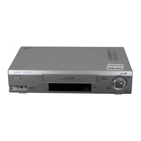
  9. Philips VR705/02 User manual

Philips VR705/02 User manual

Video
Cassette
Recorder
DECK:
Turbo
Drive
APOLLO
21
Service
Service
Service
VR705102/16/39/58
VR708A\02I07/16/39
VR766102107/16/39/58
For
technical
data
reference
is
made
to
the
Service
Manual
of
APOLLO
21
3103
785
20400.
The
present
Manual
states
only
the
differences.
Fur
technische
Daten
siehe
Service
Manual
APOLLO
21
3103
785
20390.
In
dieser
Dokumentation
sind
nur
die
Unterschiede
enthalten.
Voor
de
technische
gegevens
wordt
verwezen
naar
de
Service
Documentatie
van
de
APOLLO
21
3103
785
20420.
Alleen
de
verschillen
worden
in
deze
documentatie
gegeven.
Pour
ce
qui
est
des
caractéristiques
techniques
veuillez
vous
référer
a
la
Documentation
Service
du
APOLLO
21
3103
785
20410.
Cette
documentation
ne
reprend
que
les
différences.
Per
i
dati
tecnici
veda
il
Manuale
di
Servizio
di
APOLLO
21
3103
785
20430.
La
presente
documentazione
contene
soltanto
le
differenze.
00
0
@
8
®
Para
los
datos
técnicos
véase
el
manual
de
servicio
de
APOLLO
21
3103
785
20440.
La
presente
documentacion
contiene
solo
las
diferencias.
Safety
regulations
require
that
the set
be
restored
to
its
original
condition
and
that
parts
which
are
identical
with
those
specified
be
used.
Bei
jeder
Reparatur
sind
die
geltenden
Sicherheitsvorschriften
zu
be-
achten.
Der
Originalzustand
des
Gerats
darf
nicht
verandert
werden,
fir
Reparaturen
sind
Original-Ersatzteile
zu
verwenden.
Veiligheidsbepalingen
vereisen,
dat
het
apparaat
in
zijn
oorspronkelijke
toestand
wordt
teruggebracht
en
dat
onderdelen
identiek
aan
de
gespecificeerde
worden
toegepast
Les
normes
de
sécurité
exigent
que
l'appareil
soit
remis
a
|’état
d’origine
et
que
soient
utilisées
les
pieces
de
rechange
identiques
a
celles
spécifiées.
Published
by
FS0033
Videq
Service
Department
©
Copyright
reserved
Subject
to
modification
VR705,
VR708A
Evolution:
AA
Survey
of
types:
VR705;
VR708A:
Longplay,
FM
Audio
VR766:
Longplay,
FM
Audio,
Tape
Manager
Survey
of
versions:
/02
PAL
B/G
German
Stereo
/07
PALI,
NICAM
/16
PAL
B/G,
NICAM
&
German
Stereo
139
PAL
B/G
&
SECAML,
NICAM
/58
PAL
B/G
&
SECAM
BG/DK,
NICAM
&
German
Sereo
Survey
of
remote
controls:
VR705/VR708A
english:
RT195/101
french
(/39):
RT195/104
8622
661
95101
8622
661
95104
VR766
english:
RT118/101
french
(/39):
RT118/104
8622
661
18101
8622
661
18104
Survey
of
tape
decks:
VR705/VR708A/VR766:
WDQ-S4/2
4
Video+
2
FM-Audio
Heads
Le
prescrizioni
di
sicurezza
richiedono
che
l'apparecchio
sia
ricondotto
alle
condizioni
originali
e
che
siano
usati
ricambi
originali.
Las
instrucciones
de
seguridad
exigen
que
despus
de
la
reparacion
el
aparato
se
encuentre
en
el
estado
original
y
que
las
piezas
de
repuesto,
utilizadas
para
la
reparacion,
sean
idénticas
a
las
originales.
3103
785
21690
ab
&
PHILIPS
1-2
PCBs
&
Tape
Decks
MOTHER
BOARD
DISPLAY
CONTROL
TAPE
DECK
ADCP9.0
&
AKP31
VR766
/02
VR766
/07
|
VR766
/16
VR766
/39
VR766
/58
VR705
/02
VR705
/02
VR705
/02
VR705
/02
VR708A
/02
VR708A
/07
VR708A
/16
VR708A
/39
@
<>)
Technical
Data
Technische
Caractéristiques
Daten
Mains
voltage
oo...
ce
eeceseseseseeee
Netzspannung
................
+
TENSION
SOCEOUE
oo...
eccceeseseeteeseseeteteeees
220
—
240
V
Mains
frequency
............cccscesseseceeee
Netzfrequenz
.........
.
Fréquence.............
..
47
-
63
Hz
Power
Consumption:
........
cc
seeeeees
Leistungsaufnahme:
..
«
PuisSance
ADSOrDEE!
oo.
ee
ceceeeeceeeseneeeee
16
W
during
operation
with
Low
Power
Standby
Standby
mit
geringem
Verbrauch
avec
{a
fonction
veille
faible
consommation
<4
W
Ambient
temperature
.
....
Raumtemperatur
...
seseseeeee
PeMpérature
ambiante
oer
+10°C
to
+35°C
Relative
humidity
.......
....
Relative
Luftfeuchtigkeit
...
..
Humidité
relative
..........
..
20
—
80
%
Weight
...0..0
eee
eeee
wee
GEWICHE
oo.
c
ee
eeeeeee
i
PONDS
osi5
sc
deeccsvacet
vicin
ess
teckotv
ates
decd
ecabdoiassabeats
4.3
kg
Fast
forward/rewind
time
...............
Vor-/Rickspuizeit
..
..
Temps
(re-)bobinage
...
typ.
95s
(E180
cass.)
PoSition
Of
USE
..........eeeseeeseseseseseee
Betriebstage
...........
..
Position
d'emploi
......
..
horizontally,
max.
15°
i i
...
Video-Auflésung
.
..
Résolution
vidéo
...
4
PUGIO
:is5cect
er
esedaaslcecenctevesvaseatecensens
AUdIO!
SP
2
cdiccisvcseeresssics
saat
sosssadeianeaesbaseoodasvere
80Hz
—
10kHz
(+8dB)
AUDIO
EPS
cscccesiccctivicentsesteseseevistelsaess
80Hz
~
5kHz
(+8dB)
FM
AUdIO:
c.ccccccissscsssscsssssscsiseccasseseonsenstarcsanne
20H2
—
20kHz
(+3dB)
QD
Ce)
<p)
Technische
Datos
Tecnicos
Dati
Tecnici
Gegevens
Netspanning
..........ccccsscsesesseeessesees
TeNsiOn
de
red
........ceeeeeseeseeeseeees
Tensione
di
alimentazione..................ce
220
-
240
V
Netfrequentie
.............
....
Frecuencia
de
red.....
..
Frequenza
di
rete
«0.0.0.0...
.
47
-63
Hz
Opgenomen
vermogen:
.............00
Consumo
de
potencia:
.........00.00.
Potenza
assorbita:
......0.....
..
16
W
during
operation
met
Low
Power
Standby
con
standby
de
bajo
consumo
in
attesa
a
basso
consumo
<4W
Omgevingstemperatuur
..............06.
Temperatura
ambiente
«00.0.0...
Temperatura
ambiente
...........eccesesssessesenes
+10°C
to
+35°C
Relatieve
vochtigheid
...
....
Humedad
relativa
.....
..
Umidita
relativa
000...
.
20
~
80
%
Gewicht
cas.
sfenhieteteeei
diac
POSO2
wieceresnriheves
oltee
APOSO
isa:
seccsyiass
esses
delset
esha
.
4.3
kg
Vooruit/terugspoeltijd
............cccce
tiempo
de
(re-)bobinado
..
..
Tempo
di
(ri-)avvolgimento
....
..
typ.
95s
(E180
cass.)
Gebruikspositie
.............
...
Posicion
de
uso
...........
..
Posizione
di
funzionamento
..
..
horizontally,
max.
15°
Opplossend
vermogen
.
....
Resolucion
video
«
RISOIUZIONG
VIDEO
ooo...
eceeeeeseeseeessetseeneee
2
240
lines
VHS
PRUGIO
o5co5
dsc
2dsessccceisnadestcszeaaaventessie’
Audio
oe.
supeetes.e
AUdIO!
SP
re.
scenes
ceccaste
chegeg
al
acates
cbestacsesbae
die:
80Hz
~
10kHz
(+8dB)
Audio
LP:
....
..
80Hz
—
5kHz
(+8dB)
PM
AUdi0s
3365228
.c5-sck.cclacee
ethene
cies
20Hz
~
20kHz
(+3dB)
5-1
Exploded
View
of
the
Set
&
Mechanical
Parts
20/17
VIDE-V26669
/
DRUCK
6
Set
Parts
List
Code
Number
|
Description
3103
138
90890
FRAME
ASSY
3103
100
42400
SCREW
P3,5X16
4822
502
14431
SCREENING
SCREW
4822
256
10504
|
TD-HOLDER
20
3103
138
92120
|
CONTROL
PANEL
ASSY
VR705/02/16/58
20
3103
138
92140
|
CONTROL
PANEL
ASSY
VR705/39
20
3103
138
90190
|
CONTROL
PANEL
ASSY
VR708A/02/16
2
2
1
7
0
CONTROL
PANEL
ASSY
VR708A/07
CONTROL
PANEL
ASSY
VR708A/39
0
CONTROL
PANEL
ASSY
VR766/02/16/58
20
CONTROL
PANEL
ASSY
VR766/07
20
CONTROL
PANEL
ASSY
VR766/39
20/6
LIFT
FLAP
ASSY
VR705
20/6
LIFT
FLAP
ASSY
VR708A
20/6
LIFT
FLAP
ASSY
VR766
20/7
LEG
SPRING
LIFT
FLAP
20/11
SCREW
3X8
20/12
KEY-PCB
VR766/02/07/16/58
20/12
KEY-PCB
VR766/39
20/17
SIDE
CAP
RIGHT
VR766
20/18
SIDE
CAP
LEFT
VR766
COVER
LAQUERED
VR705
22
COVER
LAQUERED
VR708A
COVER
LAQUERED
VR766
PLASTITE
SCREW
3,5X10
30,
31
DISTANCE
HOLDER
DECK
SCREW
BK3X10
SHUTTLE
KNOB
VR705
SHUTTLE
KNOB
VR708A
1
AV-COVER
VR705/02/16/58
AV-COVER
VR705/39
41
3103
178
28350
|
AV-COVER
VR708A/02/07/16
3103
178
28450
|
AV-COVER
VR708A/39
4
41
3103
178
29460
AV-COVER
VR766/02/07/16/58
4
= =
AV-COVER
VR766/39
FOOT
ASSY
VR705
/
VR708A
FOOT
ASSY
VR766
42/2
FOOT
RUBBER
INLAY
SCREW
BK3X10
SPRING
DISTANCE
HOLDER
MOBO
3
50
60, 61,
62
Software
version
VR705
/
VR708A:
pos.7451
310317856270
EPROM
ACOP8-U53
MISCELLANEOUS
1234
4822
273
10375
EVQWMLO01
1234
4822
273
10374
EVQWmMM001
1261
4822
242
82114
EFOEC8004/T4
1262
4822
243
70938
Crystal
32,768
kHz
1270
4822
276
13951
SWITACT
1P
20MA
15V
1271
4822
276
13951
SWITACT
1P
20MA
15V
1274
4822
276
13951
SWITACT
1P
20MA
15V
1275
4822
276
13951
SWITACT
1P
20MA
15V
1281
4822
276
13951
SWITACT
1P
20MA
15V
1282
4822
276
13951
SWITACT
1P
20MA
15V
1284
4822
276
13951
SWITACT
41P
20MA
15V
1295
4822
276
13951
SWITACT
1P
20MA
15V
1920
4822
267
51255
14P
1921
4822
267
10957
CONN.
3P
1922
4822
267
10731
O6FE-BT-VK-N
1923
4822
267
10957
CONN.
3P
1924 4822
267
10955
CONN
3P
1925
4822
267
10955
CONN
3P
CAPACITORS
2200
4822
124
80238
220
uF
5,5V
2201
4822
124
12052
220
uF
6,3V
2202
4822
126
10002
100
nF
25V
2203
4822
122
33177
10
nF
50V
2221
5322
122
34123
1
nF
50V
2225
4822
124
11946
22
uF
16V
2230
4822
122
33177
10
nF
50V
2231
482212233797
47
nF
50V
2250
4822
126
13838
100
nF
2262
4822
126
13486
15
pF
63V
2263
4822
126
13486
15
pF
63V
RESISTORS
————
3210
4822
116
52175
100
R
0,5Ww
3211
4822
116
52175
100
R
0,5w
3212
482205120472
47k
O1W
3213
4822
051
20273
27
k
0,1W
3214
4822
051
20273
27
k
OW
3215 4822
051
20471
470R
O1W
3216 4822
051
20273
27
k
0,4W
3217 4822
051
20273
27
k
O1W
3218 4822
051
20273
27
k
OW
3219
4822
051
20273
27
k
O,4W
3220
4822
116
83872
220R
0,5W
3221
4822
116
83864
10
k
05W
3222
4822
051
10102
1
k
0,25w
3223
4822
051
20153
15
k
O,1W
3224
482211711504
270R
OW
3226
4822
117
11504
270
R
0.1W
3227
4822
117
10833
10
k
OW
3228
4822
117
10833
10
k
O1W
3230 4822
051
20331
330
R
0,1W
3231
4822
051
20331
330
R
0,1W
3232
4822
117
11449
2,2
k
0,1W
3233
4822
117
11449
2.2
k
0,1W
3234
4822
117
11449
2.2
k
OW
3235
4822
117
10833
10
k
OW
3236
4822
117
10353
150
R
0O,1W
3237
4822051
20472
47
k
OW
3238
4822
051
20331
330
R
0,1W
3240
4822
117
10833
10
k
O1W
3241
4822
117
10833
10
k
OW
3246
4822
051
20104
100k
O1W
3247
4822
051
20104
100k
0,1W
3250
4822
117
10965
18
k
OW
3251
4822
116
52175
100
R
0,5W
3252 4822
116
52175
100
R
0,5W
3257
482205024708
4,7
R
O6W
3258
482205024708
4,7
R
O6W
3259
4822
050
24708
47
R
O6W
3269
4822
117
10833
10
k
O1W
Display
Control
ADCP9,
AKP31
Display
Control
ADCP9,
AKP31
3270
482205120108
1
R
OjW
3271
482205120182
18k
O1W
3274
482211710965
18
k
OAW
3275
4822
051
20393
39
k
0O,1W
3279
482211710833
10k
O1W
3281
4822
051
20182
18k
0,1W
3282
482205120472
«4.7
k
OW
3284
482211710965
18
k
OW
3289
482211710833
10
k
O1W
3295
482205120393
39
«+k
«OW
3299
482211710833
10
k
O1W
3900
482205120008
O
R
O1W
3901
4822051200088
O
R
O1W
3902
482205120008
O
R
O1W
3903
4822051200088
O
R
O1W
3904
482205120008
OF
R
O1W
3905
482205120008
O
R
oOjW
3906
482205120008
oO
R
O1W
3907
482205120008
O
R
O1W
3908
4822051200088
O
R
O1W
3909
482205120008
OF
R
O1W
3910
482205120008
O
R
O1W
3911
482205120008
OF
R
OjW
3914
482205120008
O
R
O1W
3915
4822051200088
O
R
O1W
3916
482205120008
O
R
O1W
3917
4822051200088
O
R
O1W
3918
482205120008
oO
R
O1W
3921
482205120008
O
R
O1W
3924
4822051
20008
OF
R
O1W
3925
482205120008
O
R
O1W
3927
482205120008
O
R
O1W
3928
4822051
20008
O
R
O1W
3929
4822051
200088
O
R
O1W
3930
4822051
20008
O
R
O1W
3931
482205120008
oO
R
O1W
3932
482205120008
oO
R
O1W
a
at
er
COILS
i
a
ee
ee
5200
482215750961
22H
5201
4822
15711139
6,8UH
5%
een
a
ee
ee
ee
DIODES
6200
482213031983
BAT85
6212 4822
130
83081
—
LTL4231N-O71A
6213
4822
130
83081
—
LTL4231N-O71A
6214
4822
130
83081
—
LTL4231N-O71A
6219
4822
130
83081
—-
LTL4231N-O71A
6220
4822
13010227.
—
SML-210MT
6221
482213010227.
SML-210MT
6222
482213010227.
SML-210MT
6223
4822
13010227.
SML-210MT
6224
4822
13010227.
SML-210MT
6225
4822
13010227.
SML-210MT
6226
4822
13010227.
SML-210MT
6227
482213010227.
SML-210MT
6228
482213010227
SML-210MT
6229
4822
13010227
SML-210MT
6230
4822
13010227.
SML-210MT
6231
4822
13010227
SML-210MT
6232
4822
13010227.
SML-210MT
6233
4822
13010227.
SML-210MT
6234
482213010227
SML-210MT
6235
4822
13010227
SML-210MT
6236
482213010227
SML-210MT
6237
482213010227
SML-210MT
6250
482213061219
BZX79-B10
A...
Safety
component,
use
only
this
type
TRANSISTORS
&
IC’s
Display
Control
ADCP9;
Connector
PCB
ACP9
7200
4822
209
16895
TMP87CH70F-ADPU1-1U
7202
4822
135
00249
VACUUM
FLUORESC.
DISPLAY
7220
384822
218
11745
TSOP1736
7231
=4822
130
63732
MMUN2212
7232
4822
13063732
MMUN2212
7234
5322
130
60508
BC857B
7235
5322
13060508
BC857B
7236
4822
130
10872
=
MMUN2112L
7240
5322
13060508
_BC857B
7241
5322
13060508
BC857B
FLAT
CABLES
8015
4822
320
12457
3P
-
30MM
(1925-1921)
8023
4822
320
12457
3P
-
30MM
(1925-1921)
Connector
PCB
ACP9
MISCELLANEOUS
1551
4822
276
13951
SWITACT
1P
20MA
15V
1929
4822
265
11207
|
CONNECTORSOCKETE6P
4980
4822
267
10955
|
CONN3P
1981
4822
323
10448
|
CABLTREEA
1POLBUPI-1957
1982
4822
26710956
CONN.7P
1985
4822
265
10732
3
FOLD(SHIELDED)
1986
4822
265
11429
—
HSJ1406-01-020
1987
4822
267
10958
CONN.5P
1988
4822
265
11431
—
HSJ1406-01-040
1989
4822
26731773
—
HSJ41452-01-110
CAPACITORS
2551
5322
12232268
470
pF
50V
2552
4822
126
13836
=
470
A“
50V
2553
482212613196
100
nF
25V
2554
5322
122
32268
470
pF
50V
2555
4822
126
13836
470
A
50V
2556
4822126
13196
100
nF
25V
2557
4822
124
22263
220
uF
25V
2558
4822
126
13196
100
nF
25V
2559
4822
126
13836
100A
25V
2560
4822
126
13836
©6100
A
25V
2561
4822
12421732
10
pF
25V
2565
5322
122
34123
1
nF
50V
2566
4822126
13196
100
nF
25V
2567
4822
124
21732
10
pF
25V
2568
5322
122
32531
100
pF
SOV
2569
4822
124
41643
100
LIF
2570
4822
126
13836
100
A
2571
5322
12232448
=
10
pF
2572
4822
124
23052
©
100
uF
16V
2573
4822
124
23052
100
pF
16V
2580
482212233177
10
nF
50V
2581
4822
12233177
10
nF
50V
2582
5322
12234123.
1
nF
50V
2583
5322
12232268
470
pF
50V
RESISTORS
3551
482211610056
VD
R
3552
482205120105
1
M
0,1W
3553
4822
051
20684
680k
~—(0,1W
3554
4822
051
20474
470k
0,1W
3555
482205120472
4,7
k
0,1W
3556
482211610056
VD
R
3557
4822
051
20105
1
M
O1W
3558
4822
051
20684
680k
O0,1W
3559
4822
051
20474
470k
0,1W
3560
4822
051
20472
47
k
0O,1W
3561
4822
051
20759
75
R_
O,1W
3562
4822
116
83868
150
R
0O,5W
3564
4822
117
10833
10
k
O,1W
3565
4822
117
10833
10
k
OW
3566
4822
051
20333
33k
0,1W
3567
94822
117
10833
10
k
0,1W
3568
4822
051
20333
33
k
0,1W
3569
4822
117
10833
10
k
0,1W
3570
4822
051
20109
10
R
0,1W
3571
4822
051
20109
10
R
0O,1W
3572
4822
051
20109
10
R
0O,1W
3573
4822
051
20109
10
R
O,1W
3574
4822
051
20109
10
R
0O,1W
3575
4822
051
20109
10
R
0O,1W
3576
4822
117
10833
10
k
O,1W
3577
=
4822
117
10833
10
k
0,1W
3578
4822
051
20824
820k
0,1W
3579
4822
117
11454
820
R
0,1W
3580
4822
051
20104
100k
0,1W
3581
94822
117
10833
10
k
0,1W
3582
4822
051
20229
22
R
0,1W
3583
4822
051
20153
15
k
OW
3584
4822
051
20153
15
k
0,1W
3585
4822
051
20474
470k
0,1W
3586
4822
117
11149
82
k
0,1W
3587
4822
051
20472
47
k
0,1W
3588
4822
117
11503
220
R
0.1W
3900
4822
051
20008
Oo
R_
0,1W
3901
4822
051
20008
Oo
R
01W
3902
4822
051
20008
0
R
O1W
3903
4822
051
20008
Oo
R
0O,1W
3904
4822
051
20008
0
R
O1W
RESISTORS
4507
4822
051
20008
OROO
JUMP.
(0805)
COILS
5551
=
4822
157
11145
150UH
5%
5552
4822
157
11228
LANO2TB101J
5553
4822
157
11145
150UH
5%
5555
4822
157
11139
6,8UH
5%
5556
94822
157
11145
150UH
5%
5557
4822
157
11739
220UH
5%
2,4X3,4
DIODES
6551
4822
130
34197
BZX79-B12
6552
4822
130
34197
BZX79-B12
6553
4822
130
34278
BZX79-B6V8
6554
4822
130
34278
BZX79-B6V8
6555
4822
130
83757
BAS216
6556
4822
130
83757
BAS216
6557
4822
130
34278
BZX79-B6V8
6558
4822
130
34278
BZX79-B6V8
6559
4822
130
34197
BZX79-B12
6560
4822
130
34197
BZX79-B12
6570
4822
130
70059
LUH371-GK
TRANSISTORS
&
IC’s
7520
4822
209
16193
TDA7053AT
7551
5322
130
42755
BC847C
7552
5322
130
42755
BC847C
75653
4822
130
41096
BC550C
7554 4822
130
41096
BC550C
A...
Safety
component,
use
only
this
type
3-1
Keyboard
PCB
AKP91
1271
A4
1274
A2
1275
A7
1925
A4
327!
A7
3274
AB
3275
AS
1274
es10
3074
ae
PLAY
18K
be
cc)
TO
DC
ADCPS
CONNECTOR
1921
g
zB
8
1271
F315
3271
oA—@
TOP
1K8
1275
F316
3275
4
—@
REC
39K
VIDE-V26669
/
DRUCK
2
Connector
PCB
ACP9
+H
OOLNNS
TS
COMMQMDOOLL
O-AMTKR
TNO
SoOOCOCOOMNN
ADAAMDMWMWMW
MMMMMAtNOO
NMMMNMMNYD
JODOMWOOOt
O-NM+TMOOND
belelebele
Lele
lee)
NOSTNTOIMNN
BWOOWL
WO
—NM+OOM
0
ARARRARRARR
nunuNUMNNUNUN
alee
lole
ele
lelal
ONOonnwmwu+
+0
JWWOOMMaMW
O-TMNONDOHO
WWWOOWWONr
NNUNUMNHWNNMW
mrorarororara)
aaa
0000000
LWWWLIWOOO
=AMTHORAOD
NNNNHNNNU)
nNnWNNNHNWNWNUW)
Dele
leala
le
lelee
lala)
NNNIOMD
tN
TL
WOOWWWO
NWWDO-O-NNM
WwWwrmn.
00000000
nnunuNuNnNnNuWuWn
NNANNNANNN
o-O
——--hOO+OW HWWOOWOaMD
T-NAMNTONODHO
NNNNHWNNNO
nonNnnnoNnNNNuNn
NNANNNNANNN
Nonoon
mcocoa001n
TARAOW
—N
°
Or.
-O—N
toute
O-20O-N
—WNDOOD
OVADND
fo}
oO
3-2
Connector
PCB
ACP9
——_—
[<s)
f=)
(<>)
So
SER
RR
HW—
NONH=
MN
H=MMUNAUAUUMM
TLALOLOLOLAMLOR
WHNMNDM
ONNNWOD—
UHH
KH
KT
TLNT
TLOWWUUMMMT
MTLOLOLNM
0
ONDINMRRWWONNN=—W—HMUMDM
LWWOLOMOODOUIL
OMT
TOOOOOOOUWIOL
COL
COOK
DKOQOOMMM=
MDOOCOOOHOL
MOOOWOOOODOOOOL
OL
TLOOOTOLWL
<MOWWL
TMOOWWWIWWOOUOMO
=—NO—VNNNWF-
00ND
—
UM
TNO
ONO
NWI
WNO—UMO—
VM
—-
AMT
NOP-DNNO—
UTM
ONO—UMT
LNW
WONO—AIMT
NW
Or
—AUMTNUr—CUMT
NWr-WNOOO—W
10QI0O
00000000
000000
00
COLOLA
LA
LOLOLOLO
LOIN.
WW
DO
WWOF—P—P--F~
COCO
COCOLNLOLONLN
LOLOL
LN
LN
OW
OOO
WOW
W00r-
PPP
PP
PPP
00000000
00000000
CO
OLOLO
LOLOLOLO
LOLOLOLOLN
LNLOLO
LL
Wr
CULL
ONNNMNMMNMNMNMMMILOLOLD
LOLOLOLOLOLOLOLOLOLOLOLOLO
LOLOLOLO
LOLOLOLD
LALO
LO
LOLA
LOLA
LN
LALO
LALA
LA
LOLOL
LNLOLOLO
LOLNLO
LO
LNLOLO
LN
LOLNLOLN
LOLOL
LNLNLOLO.
LN
LOLOLN
LNLOLNLOLP
LOLNLNLNININLOLMLOY
oahu
ahha
MAMAN
UNIAN
IMI
MIAO
IONIC
OI
IOI
OIMMMM
MMMMMMMMMMMMMMMMMMMMMMMMMMMMMMMMMTLOLNNNMNMNDOWW
O0WWWWLOr
ir
<o
jaa)
CO
(am)
Li
LL
Co
oa
9S61
dOLIINNOI
OI
OL
nm
LEO_GREEN
esgg
8A90-6/XZ8
289
GNDESD
GNDESD
gl2sva
9gs9
9lzSsva
wpa
ouks
4
IBA9D-6ZXZ8
+
8A9D-6ZXZE
Bt
<
£999
5
psso
ysZ
Lose
240-62£XZE
esss
219-6LXZ8
hea
cy
ye
WV
W
A:
AC,
200mV/Div,
200us/Div
IC
7651
Pin
13/14
1427
orpny
L961
AOLIANNOD
re)
5
6
re)
a
6
1038
3571
1057
2572
1058
70
35
/9V10R
1036
16
13
noe
zgs¢
SS
il
cca
|
|
STABILIZER
TDA7053AT
+
7520
EKA
1034
2560
1054
«
1031
2559]
1056
4
x
i=)
3566
3568
VIDE-V26669
/
DRUCK
3
3-3
3-3
Display
Control
ADCP9
(DC)
—TDOTN
NOWTNOMWNN-OW
PNA
KH
NNANNNANNANNNNMIANG
WOTOWOL.WOOOUWL
Wt
Wd
WOON
DHO—-NMTMNORDHO—-N
ANANNANANNANNNANANS
DAAAHAIAANIAIAAHANAADAAAO
o-woo-)
—-
Oot
Oo
mr
-——
mnmM———
OtNTNOTR—O
ATNAANAN
ST
TONAN-MMNMANNNMMERDOH—RANNNMIM
—OMWM—
K—ANANANANAN
COOTOOOW<WIOWTWWOTTLLOLLLL
OL
TOLL
MOWOOL
OCOOOOOOOWL
COt—NO-—NINO—ANMO—NO—-O——
NKR
DHO—OAMF+HONDCO—AMWODHO—-—AM+
DDMAONWOOOW
OM
DBNOM+
N
TANNNNANNANN
FANN
NANNOO
—
ZOWWWOOOLLOOOOOOMOOCOOM
NODO—-+MNOR-O—-+ORO-ANTHOO—
DHKWAAAANANAANANIAIANAINNNNNNNN
NMMMMMMMMMMMMMFARARRRE
bel
=-—AMOOCOTHRHRODMOWBOOMIMNMOD
+
MMOOCOMM—
=
OON+O——o
=
PTNOANN
KH
NNANNNNANNNNNNN
SNE
IINN
=
HK
INN
RF
TOK
NN
HNN
OMOHON<OOIOOWOOOOOCOHL
OOAOOOMDHOOOOTAHDOOMAM<+
LOOMOO
AN
—O—ROAMAMT+MOR
DONM
+
ON.
DNOKN.DO—ORODHMOD—ATONMAO—AaM+NHoO
SONMMMNOO-
—-—-—-———
ANANNNMMMM
tt
tT
NORRWODDNDANHAOOCOOOCO
ANNNANNNAANAANA
ANNAN
NAN
AANNANANAAANAANAND
AANA
TTT
STS
To
Os
Dele
leie
ele
lelele
le
lelelele
le
lt
le
le
le
lee
le
ue
leis
le
le
bales
eat
lat
a
a
ae
ae
ee)
VIDE-V26669
/
DRUCK
4
3-4
3-4
Display
Control
ADCP9
(DC)
1
402
4
4S
4B
i
Pr
BS
AO
at
pt
4
1
16
198
9.-20.7-2
4
422
pies
(27
fc
|
20.pre)
|
eo
feo
|o0
Lo!
1
se
1
8e
4
2
INICBOOC0O
INTIW]S—
DISPLAY
Al
PROMS
SSG
=
O00]
=
SHOOGTOGNOUAG
==
NOR
=
Warn)
com
POW
=CUIMTIDICOOONN
I"
OOnro—
a
OF
MRO
==
SIMV100"
@Wa01
(j=
IMIPOPOMIMNON
OND
—=
CO00
10000
CLO"
PO
NOLO
—*
=
0000
PO
=
ONONOMINININD
BHWAANNMNOWO
m
J
8
5
DOLD
LD00000000
J
IACI
ICIS
8
BB
GOLOLIGOPOPONIPOPOMONIND
>
FS
SS
HN
TKWIWWNMV@A@O]ONNMO
MONDO
AOOOH
AWM
DOI
AV
GOWOO
IV
O@
INH
DO
INGO
ID
BWI
DWH
INN
AWM
OWVOI$
OI
GIN
SQW
OOLAMW
=
ON—
LAH®
MMNC
CH
EC
OOD
S$
COKE
ELA
KMMNNON
DAS
FS
PODINNMOCOCL
CEC
ZZKCKCOODO
VOW
VVOOCOE
ZOOM
75
VD
4's
SON
OL
CCC
CEA
VOE
arena
FInd
F112
IMIS
SS
SI
IDID
DNDN
CII
LILI
WIG
WIIG
CILILIWI
IW
LIGILI
WIGILIWIDI
WWIII
CI
WI
WIWIW
WWGIPIPOPONONIINONINON
NON
St
OO
PORGMOMONMONONENONONONOAY
RORORONNONOA
ROP
ORIAINGPORIAINGPORONONOAI
ROA
OPONONOPOAONOAD
RON
GPOR
OPO
POP
ORONO
POP
ORGAOPO
RPP
ONG
NON
GPONGNONGPGNGNNRIMIWOLOCD
COMMPIMIPIMNIAMIMEN@_
LONI
=
0000
NOM
=
TD?
ITI
—
—tO
DOn2
BBO
>)
|
F109
F139
,
F108
F138
|
|
l;
F105
F135
F104
orbop
p
Fos
TO
MOTHERBOARD
1925
AMB
CONNECTOR
1944
AKP91
TO
SUBPRINT
CONNECTOR
SVD
1924
1922
STBYLED_RED
ABPS
CONNECTOR
ACPS
CONNECTOR
1929
ESD_GND
AN2
GNDD
TO
SUBPRINT
TO
SUBPRINT
1
Ph
Nh
ee
NG
he
ee
oN
Oe
ee
ee
Se
4epk
IB
Ge
A
A
ote
2
ey
ee
eed
CO
ee
ClO
ee
es
Bie
ee
oe
YO
A:
DC,
5
V/Div,
5us/Div
Connector
1944
Pin
5
VIDE-V26669
/
DRUCK
5
Video
Cassette
Recorder
DECK:
Turbo
Drive
APOLLO
21
Semcon
iin
eee
Service
pee
VR810/02/07/16/39
VR910/02/07/16/39/58
Service
VR810,
VR910
For
technical
data
reference
is
made
to
the
Service
Manual
of
APOLLO
20
4822
726
15538.
The
present
Manual
states
only
the
differences.
Safety
regulations
require
that
the
set
be
restored
to
its
original
condition
and
that
parts
which
are
identical
with
those
specified
be
used.
Published
by
FS0016
Videg
Service
Department
Printed
in
the
Netherlands
Show
view
/
Videoplus+
is
registered
by
the
Gemstar
Development
Group
ad
©
Copyright
reserved
Evolution:
AA
Survey
of
types:
VR710/VR765:
Longplay,
FM
Audio,
Tape
manager
VR810:
Longplay,
FM
Audio,
Tape
manager,
Jog/Shuttle
VR910:
Longplay,
FM
Audio,
Tape
manager,
Jog/Shuttle
Survey
of
versions:
/02
PAL
B/G
German
Stereo
107
PALI,
NICAM
/16
PAL
B/G,
NICAM
&
German
Stereo
139
PAL
B/G
&
SECAM
L,
NICAM
&
German
Stereo
/58
PAL
B/G
&
SECAM
BG/DK,
NICAM
&
German
Stereo
Survey
of
remote
controls:
VR710/VR765:
english:
RT118/101
8622
661
18101
french
(/39):
RT118/104
8622
661
18104
VR810
:
english:
RT119/101
8622
661
19101
french
(/39):
RT119/104
8622
661
19104
VR910
:
english:
RT517/101
8622
665
17101
french
(/39):
RT517/104
8622
665
17104
Survey
of
tape
decks:
VR710/VR765:
WDQT-S4/2
VR810,
VR910:
WDQT-S4/2S
4
Video+
2
FM-Audio
Heads
4
Video+
2
FM-Audio
Heads
Swing
search
3103
785
20400
PHILIPS
Subject
to
modification
eB
1-2
Table
of
contents
Page
Chapter
1
TECHNICAL
DATA
AND
FEATURES
Survey
of
sets
and
features
Survey
of
sets
and
PCBs,
Technical
specifications
..
Safety
instructions
Direction
for
use
Chapter
3
PRINTED
BOARDS
Adjustment
Procedures
..........ccccccssssssscsescessssscscssessscerecsesesuee
3-1
List
of
abbreviations
..........ccccsceeecssseececcececcscscsacsatscsssecssce
3-2
Wiring
diagram
oo.
eecesesssessescessscsssecssssesecscesseessssscscecesees
3-3
Block
diagram
Video
.
a
SAIS
Block
diagram
Audio
..........ccccccesecessscessesescscecsscecececececseases
3-6/7
Block
diagram
Digital
...........cccccscsccseccsesessessesesesteseseesssees
3-8/9
Block
diagram
power
paft
uu...
cccccccscsssscscescesseseseseeeees
3-10/11
Power
supply
ASM
PCB
drawing
ASM
u.......ccccccscssescscsesssssscscscsssvscerecacacavacecaececes
3-12
Circuit
diagram
ASM
.......ccccccccccccsssseseseceesesssscacereccsesseecseens
3-13
Mother
Board
PCB
drawing
Mother
Board
........c.cccsccsscssssesesecsesesteseees
3-14/17
Circuit
diagram
(PS)
oo...
we
3°18
Circuit
diagram
Front
End
(FV)
...c.c.cccesccecescssseccsecessssescscees
3-20
Circuit
diagram
Stereo
Decoder
(FM_STEREO_TDA).........
3-22
Circuit
diagram
Stereo
Decoder
(FM_STEREO_MSP).........
3-23
Audio
FM
(AF)
circuit
diagram
........0..cceceseseeccceseseesees
wee
8°24
Circuit
diagram
Erase
Oscillator
(ER)
3-25
Audio
linear-AL
circuit
diagram
......c.ccccccecsescecesecsseessesseses
3-26
Video
Signal
Processing
(VS)
circuit
diagram
...............0-
3-29
Head
Amplifier
(HA)
circuit
diagram
.........cccccecccccssesssceseseeos
3-30
SECAM
Processing
(VS_SEC)
circuit
diagram
....
wee
3°33
Chroma
Noise
Reduction
(CNR)
circuit
diagram
..........
vie
3934
In/Out
(lO)circuit
diagram
.........cccccesssseesescssseseseseeeeeees
wee
3°35
Central Control
(AIO1)
circuit
diagram
oo...
ccceceeeesesseees
3-36
Deck
Electronics
(DE)
circuit
diagram
.........ccceesecccceceeees
3-39
Central Control
(AlO2)
circuit
diagram
........
we
3-40
On
Screen
Display
(VPO)
circuit
diagram
........cccseccseeeeee
3-41
Circuit
diagram
FOME,
VPS,
PE
uuu...
ccecccscscsececscseseeseeseeees
3-42
Display
Control!
ADCP18
PCB
drawing
ADCP18
.........
ce
Circuit
diagram
ADCP18
(DC)
Connector
PCB
ACP18
PCB
drawing
ACP18
.o.......cccccccssssesssssesscesssecseecesesesecseseares
3-46
Circuit
diagram
ACP
18
oc.
ccecccsesescsssscsscsssessescecscsesesssesessees
3-47
GB
Page
Chapter
4
TAPE
DECK
Deck
parts
replacement
Capstan
motor
....
Pressure
roller
Roller
unit
right
..........
cc
ceesessesssseeeeee
Rollertunit
lett
ccc
2eseoeciedescseca
2.
acddetee
ahh
eRe
Adjustments
Tape:
path
jaciieccrssccdosiectendicd
teventatieeihaictlveechs
4-5
»Roller
unit
left;
roller
unit
right"
0.0...
cscccccsceccssssessessseces
4-5
AIC
HOA
0.
oies
cs
iecssasisavavsintarscennsvanses
Bivivaisil
sabato
Rech
4-5
Horizontal
distance
..........cccccsccesescecesesescsccscessacsnescacsavsseeee
4-6
BARE:
DANG
sso
c28t
ote
aasedivepcaseccsseiacensseesetvdives
tacweisteuve
ee
eeacce
4-6
Tape
tension
adjustment
oo...
cee
cccccsssessesessessesescseeceess
4-6
Friction
Clutch
COntrol
.......cccccscccscessecssescssescsssecavsecasscessseveve
4-6
Reverse
brake
Control
.......c.cccccessceccscssescsccscssescscsesasessccesseee
4-6
Top
view,
Underside
View
.........cccccccssssesssssesssccesseseccesscsess
4-7
Exploded
view
Cleaning
and
lubrication
...0.....c.ccsescscessesssesssseeseseeecseeceneens
4-8/9
Pats:
MISE
2ssisecasictcedgavdsintss
aatees
se
cctasll
eas;
ofa
eataesecscsntl
ives:
4-10
Chapter
5
PARTS
LIST
Exploded
view
of
cabinet
parts
Cabinet
parts
0...
Power
*SUPDIY...12s00:
2
ctecsedieesaneisGicnciietousd
ci
awetsoeaecite,
Mother
Board
2/00.
.esctesiscdjscshs
Bote
ottidala
a
deattehehed
ell
bestas
Display
Control
ADCP
18
...
Connector
PCBACP'18
.........cccee
DRUCK
1
See
+
e
R
p.
Mode.
Scart
1/2
“Audio
Dubbing
|
Cinema
Link
(pin
10)
.
Dolby
virtual
surround
Features
Specification
Items
VR705
/02
VR705
/16
VR705
/39
VR705
/58
VR708A
/02
Sema
Stereo
Rea:
Rec/Pb
PAL
~
Rec/Pb
SECAM
Rec.
Pb
MESECAM
|
pack]
PaG|
P
C
Y
Gu
suide
Channel Mapping
Time/Date
Download
_
Synchro
€
edit
Auto
Tape
Length
Recognition
WA
|
Wind/Rew.
Time
(E180)
VISS_
[
icture
Control
Noise
canceller
E
“Smart
Picture
VPS/PDC
Smart
‘sound
Tape
Manager
VR708A
/07
VR708A
/16
VR708A
/39
VR766
/02
VR766
/07
VR766
/16
1-3
VR766
/39
VR766
/58
1-3
1-4
PCBs
&
Tape
Decks
DISPLAY
CONTROL
TAPE
DECK
ADCP
18
ADCP18.1
|
WDQT-S4/2
|
WDQT-$4/2S
‘|
ACP18&.4
;
jams
|
POWER
SUPPLY
awe
MOTHER
BOARD
VR710;
VR765
/02
VR710;
VR765
/07
VR710;
VA765
16
VR710;
VR765
/39
VR710;
VR765
/58
VR810/02
a
VRB1007
See
VR810/16
VR810/39.
VR910/02
VEQLOIOT
cis
VR910/16
VR910/39
VR910/58
ast
bss
@®
<>)
Technical
Data
Technische
Caractéristiques
Daten
Mains
voltage
...........cscceseceseseseeeee
Netzspannung
..........ceeeecseseeeees
TENSION
SECEOUF
.........ccceeecsessessesstscevseetseeeeee
220
~
240
V
Mains
frequency
...........cccceeeseeeeee
Netzfrequenz
ooo...
eee
cceeeseeeeees
Fréquence..............
...
47
—
63
Hz
Power
consumption:
.....0..00.
eee
Leistungsaufnahme:
.........0.00..000.
Puissance
absorbée:
0...
eeeeceeeeee
16
W
during
operation
with
Low
Power
Standby
Standby
mit
geringem
Verbrauch
avec
la
fonction
veille
faible
consommation
<4W
Ambient
temperature
..........0.0000.
Raumtemperatur
.........0.0.cce
eee
Température
ambiante
............ccececesseeeeees
+10°C
to
+35°C
Relative
humidity
.........0.ccc
Relative
Luftfeuchtigkeit
..
we
Hurmidité
relative
oo...
cc
eeseseesseseessseesseseseees
20-80%
Weight
...........cccccssssssecsscsseeeseteees
Gewicht
oo...
ceeeeeeeeeeeee
Rise
WPOINS
ah
cetetanthies
cccssneass
we
4.3
kg
Fast
forward/rewind
time
...............
Vor-/Ruckspuizeit
..
....
Temps
(re-)bobinage
.
wa
typ.
95s
(E180
cass.)
Position
of
US
ooo...
cceeeeeeeseeseeee
Betriebsiage
...........
ve
POSItION
B'EMPIOL
«0...
ceesecesssesscesctsteeseesees
horizontally,
max.
15°
Video
resolution
oo...
Video-Auflésung
.
wees
RESOIULION
VIdEO
0.0...
eceecseseeseeeesseetecsrenseees
2
240
lines
VHS
AUDIO
csssscasicestascsssssccciaccevvasedevesssestes
PUIO
ssessdsisseesscssecesscsetenvseorscitansedscasee
Audio
SP:
............
....
80HZ
—
10kKHz
(+8dB)
Audio
LP:
..
.
8OHZ
—
5kKHz
(+8dB)
PM
AUGIOS
fo.
0c:
ccstvzcdicciicersescceceedsanitscotnvsesscnnee
20Hz
—
20kHz
(+3dB)
a)
Cc)
Ci)
Technische
Datos
Tecnicos
Dati
Tecnici
Gegevens
Netspanning
...........cccssscecescsseceeees
Tension
de
red
oo...
cccceceeeceeeees
Tensione
di
alimentazione
.....0......eeeeceeeeeee
220
-
240
V
Netfrequentie
oo...
Frecuencia
de
red.........
...
Frequenza
di
rete
oo...
47
~
63
Hz
Opgenomen
vermogen:
Consumo
de
potencia:
Potenza
assorbita:
.............ccsscesssesscsesssesees
16
W
during
operation
met
Low
Power
Standby
con
standby
de
bajo
consumo
in
attesa
a
basso
consumo
<4W
Omgevingstemperatuur
..................
Temperatura
ambiente
0.0.00...
Temperatura
ambiente
..............cccesseseseeee
+10°C
to
+35°C
Relatieve
vochtigheiad
......
Humedad
relativa
0.0...
Umidita
relativa
0...
eeeeeceeeceeescsssasssens
20-80%
Gewicht
0...
cceeeeseeeee
P@S0
oe.3.
heieltlahciecans
sone
POSO
ios
couagcesedanesuies
isd
ces
dedeuscnibaceseas
ted
gectecete
ats
4.3
kg
Vooruit/terugspoeltijd
..............
tiempo
de
(re-)bobinado
..
.-.
Tempo
di
(ri-Javvolgimento
......
cece
typ.
95s
(E180
cass.)
Gebruikspositie
000.000.0000...
Posicién
de
uso
.........00..
....
Posizione
di
funzionamento
...
....
horizontally,
max.
15°
Opplossend
vermogen
....
Resoluci6n
video
«0.0.0.0...
Risoluzione
Video
..0......c.eccccscesescccsseceeteees
2
240
lines
VHS
AUdIO
oo.
cc
cscseeseeeeeeeee
ees
PUNO
65
eee
oS
oracactdiniceticness
AUGIG
SP
oe
cscs
sre
tee
AN
Me
deceea
a
ecu
80Hz
—
10kHz
(+8dB)
Audio
LP:
..
w+
8OHZ
—
S5KHz
(+8dB)
FIM
AUGIO!
o.oo
cece.
ccc
hesscesdesantcectesestscaeisbencaess
20Hz
—
20kHz
(+3dB)
Safety
instructions
—
Safety
regulations
demand
that
the
set
be
restored
to
its
original
condition
and
that
components
identical
with
the
original
types
be
used.
Safety
components
are
marked
by
the
symbol
A
—
Ail
1Cs
and
many
other
semi-conductors
are
susceptible
to
electrostatic
discharges
(ESD).
Careless
handling
during
repair
may
reduce
life
drastically.
When
repairing,
make
sure
that
you
are
conneted
with
the
same
potential
as
the
mass
of
the
set
via
a
wrist
wrap
with
resistance.
Keep
components
and
tools
on
the
same
potential.
-A
set
to
be
repaired
should
always
be
connected
to
the
mains
via
a
suitable
isolating
transformer.
—
Never
replace
any
modules
or
any
other
parts
while
the
set
is
switched
on.
~
Use
plastic
instead
of
metal
alignment
tools.
This
in
order
to
prelude
short-circuit
or
to
prevent
a
specific
circuit
from
being
rendered
unstable.
Remarks
—
The
direct
voltages
and
oscillograms
ought
to
be
measured
relative
to
the
set
mass.
EXCEPTION
At
the
power
supply,
the
DC
voltages
and
the
oscillograms
at
the
primary
side
are
measured
to
LIVE
GND.
~
The
direct
voltages
and
oscillograms
mentioned
in
the
diagrams
ought
to
be
measured
with
a
colour
bar
signal
and
the
picture
carrier
at
503.25
MHz
(C25).
—
The
oscillograms
and
direct
voltages
have
been
measured
in
RECORD
or
PLAY
mode.
-
The
semiconductors,
which
are
mentioned
in
the
circuit
diagram
and
in
the
parts
lists,
are
fully
exchangeable
per
position
with
the
semiconductors
in
the
set,
irrespective
of
the
type
designation
of
these
semiconductors.
Sicherheitshinweise
—
Die
Sicherheitsvorschriften
erfordern
es,
daf
sich
das
Gerat
nach
der
Reparatur
in
seinem
originalen
Zustand
befindet
und
da
die
zur
Reparatur
benutzten
Ersatzteile
mit
den
Originalersatzteilen
identisch
sind.
Sicherheits-Bauteile
sind
mit
der
Markierung
A
versehen
~
Alle
IC’s
und
Halbleiter
sind
empfindlich
gegen
elektrostatische
Entladungen
(ESD).
Unvorschriftmassige
Behandlung
von
Halbleitern
im
Reparaturfall
kann
zur
Zerstérung
dieser
Bauteile
oder
zu
einer
drastischen
Reduzierung
der
Lebensdauer
fihren.
Sorgen
Sie
dafiir,
da
Sie
sich
im
Reparaturfall
Uber
ein
Armband
mit
Widerstand
auf
dem
gleichen
Potential,
wie
die
Masse
des
Gerates
befinden.
Alle
Bauteile,
Werkzeuge
und
Hilfsmittel
sind
auf
das
gleiche
Potential
zu
legen.
—
Ein
zu
reparierendes
Gerat
ist
immer
iiber
einen
Trenntransformator
an
die
Netzspannung
anzuschlieRen.
—
Bei
eingeschaltetem
Gerat
diirfen
keine
Module
oder
sonstige
Einzelteile
ausgetauscht
werden.
—
Zum
Abgleich
sind
ausschlieRlich
Kunststoffwerkzeuge
zu
benutzen
(keine
Metallwerkzeuge
verwenden).
Dadurch
wird
vermieden,
da
ein
Kurzschlu&
entstehen
kann
oder
eine
Schaltung
instabil
wird.
Anmerkungen
—
Die
Gleichspannung
und
Oszillogramme
sind
gegen
Geratemasse
zu
messen.
AUSNAHME
Beim
Neizteil
sind
die
Gleichspannungen
und
Oszillogramme
auf
der
Primarseite
gegen
Live
GND
gemessen.
~
Die
Gleichspannungen
und
Oszillogramme
angefiuhrt
in
den
Schaltbildern
sotlen
unter
folgenden
Bedingungen
gemessen
werden:
Farbbalkensignal,
Bildtrager
auf
503.25
MHz
(C25)
—
Die
Oszillogramme
und
Gleichspannungen
sind
in
RECORD
oder
PLAY
gemessen.
Die
in
den
Sticklisten
aufgefiihrten
Bauteile
sind
positionsweise
volt
auswechselbar
gegen
die
Bauteile
in
dem
Gerat,
ungeachtet
der
etwaigen
Typenbezeichungen.
\
Avertissements
—
Les
normes
de
sécurité
exigent
qu’aprés
réparation
l'appareil
soit
remis
dans
son
état
d'origine
et
que
soient
utilisées
les
piéces
de
rechange
identiques
a
celles
spécifiées.
Les
composants
de
sécurité
sont
marqués
A
—
Tout
les
IC
et
beaucoup
d’autres
semi-conducteurs
sont
sensibles
aux
décharger
statiques
(ESD).
Leur
longévité
pourrait
étre
considérablement
écourté
par
le
fait
qu'aucune
précaution
n'est
prise
a
leur
manipulation.
Lors
de
reparations
s'assuret
dé
bien
étre
relié
au
méme
potential
que
la
masse
de
l'appareil
et
enfiler
le
bracelet
serti
d’une
résistance
de
sécurité.
Veiller
4
ce
que
les
composants
ainsi
que
les
outils
que
l'on
utilise
soient
également
a
ce
potentiel.
—
Toujours
alimenter
un
appareil
a
réparer
a
travers
un
transfo
d'isolement.
—
Ne
jamais
remplacer
les
modules
ni
d'autres
composants
quand
l'appareil
est
sous
tension.
—
Pour
l'ajustage,
utiliser
des
outils
en
plastique
au
lieu
d'instruments
métalliques.
Ceci
afin
d’éviter
les
court-circuits
et
exclure
!’instabilité
dans
certains
circuits.
Observations
—
La
mésure
des
tensions
continues
et
des
oscillogrammes
doit
se
faire
par
rapport
a
la
terre
de
l'appareil.
EXCEPTION
;
Sur
l'unité
d’alimentation
la
tension
continue
et
l'oscillogramme
sont
mesurés
sur
le
céte
primaire
en
Live
GND.
—
La
mésure
des
tensions
continues
et
des
oscillogrammes
figurant
sur
le
schéma
doit
se
faire
dans
un
signal
de
barre
couleur
porteuse
image
sur
503.25
MHz
(C25).
—
Les
oscillogrammes
et
tension
sont
mésurées
en
mode
RECORD
ou
PLAY.
—
Les
semi-conducteurs
indiqués
dans
le
schéma
de
principe
et
a
la
liste
des
compostants,
sont
interchangeabies
par
repére
sur
ce
chassis
avec
les
semi-conducteurs
de
l'appareil
quelie
que
soit
la
désignation
de
type
donnée
sur
ces
semi-conducteurs.
Veiligheidsinstructies
—
Veiligheidsbepalingen
vereisen,
dat
het
apparaat
in
zijn
oorspronkelijke
toestand
wordt
teruggebracht
en
dat
onderdelen,
indentiek
aan
de
oorspronkelijke,
worden
toegepast.
De
veiligheidsonderdelen
zijn
aangeduid
met
het
symbool
A
—Aile
IC’s
en
vele
andere
halfgeleiders
zijn
gevoelig
voor
elektrostatische
ontladingen
(ESD).
Onzorgvuldig
behandelen
tiidens
reparatie
kan
de
levensduur
drastisch
doen
verminderen.
Zorg
ervoor,
dat
U
tijdens
reparatie
via
een
polsband
met
weerstand verbonden
bent
met
hetzelfde
potentiaal
als
de
massa
van
het
apparaat.
Houd
componenten
en
hulpmiddelen
ook
op
ditzelfde
potentiaal.
—
Sluit
een
apparaat
dat
gerepareerd
wordt
altijd
via
een
scheidingstransformator
aan
op
de
netspanning.
—
Verwissel
nooit
modules
of
andere
onderdelen
terwijl
het
apparaat
is
ingeschakeld.
—
Gebruik
voor
het
afregelen
plastic
i.p.v
metalen
gereedschap.
Dit
om
mogelijke
kortsluiting
te
voorkomen
of
een
bepaalde
schakeling
instabiel
te
maken.
Opmerkingen
~
De
gelijksspanningen
en
oscillogrammen
dienen
gemeten
te
worden
ten
opzichte
van
de
apparaat
aarde.
—
De
gelijksspanningen
en
oscillogrammen
vermeld
in
de
schema’s
dienen
gemeten
te
worden
met
een
kleurbalkensignaal
beelddraaggolf
op
503.25
MHz
(C25),
—
De
oscillogrammen
en
gelijksspanningen
zijn
in
RECORD
of
PLAY
mode
gemeten.
:
—
De
halfgeleiders,
die
in
het
pricipeschema
en
in
de
stuklijsten,
zijn
vermeld,
zijn
per
positie
volledig
uitwisselbaar
met
de
halfgeleiders
in
het
apparaat,
ongeacht
de
typeaanduiding
op
deze
halfgeleiders.
1-6
Avvertimenti
-
Le
prescrizioni
di
sicurezza
richiedono
che
l'apparecchio
sia
ricondotto
alle
condizioni
originali
e
che
siano
usati
ricambi
originali.
Componenti
di
sicurezza
sono
marcati
con
A
—
Tutti
gli
IC
e
semiconduttori
sono
sensibili
a
scariche
elettrostatiche
(ESD).
Noncuranze
durante
la
riparazione
di
semiconduttori
possono
danneggiarli
o
condurre
ad
una
riduzione
drastica
della
durata.
Durante
la
riparazione
-
,
agsicurarsi
di
essere
collegati
allo
stesso
pdtenziale
attraverso
un
bracciale
di
protezione
contro
scariche
elettrostatiche.
Inoitre
tenere
anche
tutti;
componenti
e
gli
attrezzi
a
questo
potenziale.
—
Apparecchi
da
riparare
bisogna
collegarli
sempre
via
un
trasformatore
isolante
(separatore)
alla
tensione
normale.
~Non
scambiare
moduli
o
altri
componenti
quando
l’apparecchio
é
in
funzione.
—
Per
l'accordo
usare
soltanto
attrezzi
di
plastica
(non
usare
attrezzi
metallici).
Cosi
si
evitano
cortocircuiti
e
collegamenti
instabili.
Osservazioni
~
Misurare
le
tensioni
continue
e
gli
oscillogrammi
riferiendosi
alla
massa
dell’apparecchio.
ECCEZIONE
Le
tensioni
continue
e
gli
oscillogrammi
dall’alimentatore
sono
misurati
sulla
parte
primaria
contro
GND-Live.
~
Le
tensioni
continue
e
gli
oscillogrammi
indicati
negli
schemi
di
collegamento
devono
essere
misurati
secondo
le
condizioni
seguenti:
segnale
barre
colore,
portante
dell’immagine
su:
503.25
MHz
(C25).
—
Gli
oscillogrammi
e
le
tensioni
continue
sono
misurati
in
RECORD
o
PLAYBACK.
~
|
componenti
indicati
nelle
liste
sono
intercambiabili
con
quelli
nell’'apparecchio
nonostante
l’'eventuale
denominazione
di
modelli.
Avisos
-
Las
instrucciones
de
seguridad
exigen
que
después
de
la
reparacion
el
aparato
se
encuentre
en
el
estado
original
y
que
las
piezas
de
repuesto,
utilizadas
para
la
reparacién,
sean
idénticas
a
las
originales.
Los
componentes
de
seguridad
estan
marcados
con
A
~
Todos
los
IC
y
semiconductores
son
sensibles
a
descargas
electrostaticas
(ESD).
Un
tratamiento
no
conforme
a
las
instrucciones
de
semiconductores
en
caso
de
reparacion,
podria
llevar
a
la
destruccién
de
estos
componentes,
o
a
una
reduccion
drastica
de
la
duracion.
Tenga
cuidado
de
que,
en
caso
de
reparacion,
estar
al
mismo
potencial
que
la
masa
del
aparato,
por
una
pulsera
con
resistencia.
Ponga
todos
los
componentes,
herramientas
y
recursos
al
mismo
potencial.
—
Para
reparar
un
aparato
hay
que
conectarlo
siempre
a
la
alimentacion
a
traves
de
un
transformador
de
aislamiento.
-
Cuando
un
aparato
esta
en
marcha
no
pueden
ser
cambiados
médulos
u
otras
piezas
de
repuesto.
—
Para
los
ajustes
hay
que
utilizar
exclusivamente
herramientas
de
plastico
(nunca
herramientas
metalicas).
Asi
se
evitaran
cortocircuitos
y
circuitos
inestables.
Notas
—
Hay
que
medir
las
tensiones
continuas
y
los
oscilogramas
contra
la
masa
del
aparato.
UITZONDERING:
Bij
het
netgedeelte
zijn
de
gelijkspanningen
en
oscillogrammen
aan
de
primaire
kant
tegen
Live
GND
gemeten.
~
Las
tensiones
continuas
y
los
oscilogramas
mencionados
en
los
esquemas
tienen
que
ser
medidos
de
manera
siguiente:
sefial
barra
de
color
portadora
de
imagen
en
503.25MHz
(C25)
-
Los
oscilogramas
y
las
tensiones
continuas
son
medidas
en
»RECORD"
y
,PLAYBACK"
—
Los
componentes
mencionados
en
las
listas
se
los
puede
cambiar
por
los
componentes
en
el
aparato,
a
pesar
de
eventuales
designaciones
de
tipos.
ADJUSTMENT
INSTRUCTIONS
1.Tape
Manager
Set
the
tape
manager
number
This
setting
has
to
be
done
after
replacement
of
the
EEPROM.
-
Call
up
the
service
test
program,
select
step
43
-
the
display
shows
T-:--:43
using
the
remote
control,
type
in
the
last
tree
digits
of
the
serial
number,
located
on
the
type
plate
of
the
set
press
the
ok
button
exit
the
service
test
program.
2.
Video
signal
processing
(VS-SEC)
Service
tasks
after
replacement
of
ICs
7004,
7072:
Before
commencing
adjustment:
Call
the
service
test
program
and
enter
Step
10
(Dummy
mode).
Remove
the
drive
from
the
motherboard.
2.1
3.3
MHz
adjustment
[3089]
(for
SECAM)
Purpose:
To
adjust
the
mixing
oscillator
Consequences
of
incorrect
settings:
Cross
patterns
in
coloured
areas,
coloured
noise.
1.2
MHz
sinus
D
d
167072")
naan
gia
ae
100mVpp,
R3065
pin
17
playback
+5V
on
IC
7072
6,
R3064
Oscilloscope
adjust
to
Video
pattern
optimum
generator
sinus
Sinus
generator
A:
AC,
50mV/Div,
50ns/Div
IC
7072
Pin
17
2.2
SECAM
chrominance
record
current
adjustment
[3088]:
Purpose:
To
set
the
optimum
record
SECAM
chroma
level.
Symptom,
if
incorrectly
set:
if
the
record
level
is
too
high,
beats
may
appear
on
the
picture.
If
the
level
is
too
low,
the
colour
may
be
de-
graded.
|
TP
|
Ady.
|
MODE
|
__INPUT
CSRV
Dummy
mode
(VIDEO
IN
E2)
pos.9068
|
R3088
Record
Red
Picture
SECAM
TAPE
Preset
E2
75%
Saturation
MEAS.
EQ.
SPEC.
Oscilloscope
Video
Pattern
A=240
+
15
MVpp,
Generator
Notes:
With
varying
frame
amplitudes,
the
setting
is
made
for
the
greatest
amplitude.
A:
AC,
50mV/Div,
20us/Div
3-2
List
of
Signal
Abbreviations
2x
Colour
subcarrier
..
Scart
1/2
Pin
10
Scart
1
pin
8
input
Scart
1
pin
8
high
level
Scart
1
pin
8
medium
level
Scart
2
pin
8
input
Capstan
motor
supply,
switched
Adress
lines
..
Audio
erase
head
Audio
from
frontend,
left
Audio
from
frontend,
right
..
Automatic
frequency
control
..
Audio
from
frontend
Automatic
gain
control
..
Audio
heads
..
Audio
input
scart
1,
left
..
Audio
input
scart
1,
right
..
Audio
input
scart
2,
left
..
Audio
input
scart
2,
right
..
Audio
left
from
cinch
connector
Audio
right
from
cinch
connector
Audio
left
from
Front
connector
..
Audio
right
from
front
connector
..
Audio
mono
to
the
modulator
Audio
mono
playback
Audio
mono
record
..
Analog
voltage
from
keyboard
matrix
..
NICAM
Audio,
left
..
NICAM
Audio,
right
..
Audio
output
from
scart
1,
left
...
Audio
output
from
scart
1,
right
Audio
output
from
scart
2,
left
Audio
output
from
scart
2,
right
...
Audio
playback
head
...
Audio
record
head
Chroma
Automatic
gain
control
Capstan
regulation
voltage
...
Colour
killer
detection
...
Chroma
Noise
Reduction
...
Chrominance
PAL
record
...
Capstan
reverse
...
Colour
rotation
Chip
Select
0
Chip
Select
1
...
Colour
phase
switching
for
LP
feature
mode
..
Colour
system
information
Chrominance
secam
playback
Chroma
to
Noise
Reduction
...
Chrominance
secam
record
9V/17V
switching
for
capstan
motor
Composite
sync pulse
CTL1/2
ee.
Control
track
signal
DO-7
0...
eceeeteee
Data
lines
DC_RESET
.....
Reset
Display
Control
DRUM
........0..
Head
wheel
control
..
Synchro-Edit
control
signal
..
Envelope
comparator
signal
Feature
frame
pulse
Capstan
tacho
pulse
digital
...
FM
audio
playback
...
FM
audio
record
...
FM
video
playback
..
FM
video
record
...
Follow
Me
(video
signals
equal)
...
Colour
subcarrier
..
Threading
tacho
..
Threading
tacho
digital
..
Heater
for
displaytube
high
Heater
for
displaytube
low
GB
VIDOUT2
Heater
voltage
control
signal
..
Head
pulse
video
..
Head
pulse
audio
..
Head
Select
Control
(SP/LP)
..
Main
erase
oscillator
on/off
..
Deck
switch
..
Interrupt
..
Inverse
power
on
reset
Inverse
record
FM-audio
Inverse
Record
Audio
Linear
..
Inverse
Record
Video
..
Inverse
stand
by
..
Crosstalk
Reduction
..
Control
pulse
amplification
low
..
Long
play
heads
..
Main
erase
head
..
Loop
through
pin
16
scart
2/1
..
Audio
mute
..
Not
connected
..
Shift
register
bus
data
..
OSD
Frame
pulse
..
Playback
Video
Head
wheel
position/-speed
Pin
10
scart
1/2
output
Pin
10
scart
1/2
input
Power
on
reset
..
PAL/SECAM
Switch
..
Output
Enable
RAM/ROM
..
Record
protection
..
Receive
Data
..
Secam
band
1
..
HC
bus
clock
..
HC
bus
data
..
YCA
IIC
bus
clock
YCA
IIC
bus
data
High
Speed
IiC
bus
clock
.
High
Speed
IIC
bus
data
..
Sound
filter
switch
Standard
play
heads
Shift
Register
Clock
-
..
Second
sound
intermediate
frequene'
..
Strobe
pulse
for
shiftregister
..
Head
switching
pulse
..
Control
track
pulse
..
Tape
end
detection
Tape
start
detection
Threading
motor
in/out
Loading
motor
on/off
Tracking
information
audio
/
Audio
level
indication
Tracking
information
video
..
Transmit
Data
..
Video
to
signal
electronics
Signal
before
Y-CCD
Signal
after
Y-CCD
..
Video
from
front
connector
Video
from
front
end
Video
output
scart
1
Video
output
scart
2
Video
input
scart
1
Video
input
scart
2
Control
sync
pulse
inversion
headphone
volume
..
Video
from
OSD
part
..
Video
from
signal
electronics
..
Control
track
write/read
..
Write
enable
for
RAM
..
Wind
tacho
left
..
Wind
tacho
left
digital
..
Wind
tacho
right
Wind
tacho
right
digital
3-3
3-3
ASM
Power
Supply
Component
side
8004...
#
2690.
1960
APA,
8002...
#
2688.
(
5
1912
|
Rotating
Trafo-Conn.
1911
1945
[ARARARAR
AAR
1951
VideoOut
GNDVSIO
GNDVSIO
VIDEOIN
SCART
1/2
e961
YHOLVINGOWTHANNL
iagram
iring
D
AUDIO-CONTROL-HEAD
8018...
#2721.
MOBO-DECK
Motrerboard
ex,
Display
Control
Component
side
1958
“8692
#°E108
&
8
3
8020...
#
2699.
‘Component
sige
ADCF18
Display
Control
6892
#
2208
0022
#
"1208
+108
EDIT
VIDEO SYNC-
VID
in
“0692
#2108
©O©®
e
&
oO
ue?
°
S46
3
(ome
2
8
ze
c
/IDE-V25978
/
DRUCK
1

This manual suits for next models

12

Other Philips VCR System manuals

Philips VR 420 User manual

Philips

Philips VR 420 User manual

Philips 33DV1 System manual

Philips

Philips 33DV1 System manual

Philips VR285/05 User manual

Philips

Philips VR285/05 User manual

Philips VR 337 User manual

Philips

Philips VR 337 User manual

Philips VR 727 User manual

Philips

Philips VR 727 User manual

Philips VR288 User manual

Philips

Philips VR288 User manual

Philips VR910/07 User manual

Philips

Philips VR910/07 User manual

Philips VR 676 User manual

Philips

Philips VR 676 User manual

Philips vr530 User manual

Philips

Philips vr530 User manual

Philips VR750 User manual

Philips

Philips VR750 User manual

Philips VR 647 User manual

Philips

Philips VR 647 User manual

Philips VR 212 User manual

Philips

Philips VR 212 User manual

Philips VR287/07 User manual

Philips

Philips VR287/07 User manual

Philips VRA431AT User manual

Philips

Philips VRA431AT User manual

Philips VR171/16 User manual

Philips

Philips VR171/16 User manual

Philips VR550/39 User manual

Philips

Philips VR550/39 User manual

Philips RT24A/00T User manual

Philips

Philips RT24A/00T User manual

Philips VR1010/75 User manual

Philips

Philips VR1010/75 User manual

Philips VRB411AT User manual

Philips

Philips VRB411AT User manual

Philips VR323 User manual

Philips

Philips VR323 User manual

Philips VR623CAT User manual

Philips

Philips VR623CAT User manual

Philips VR 678/16 User manual

Philips

Philips VR 678/16 User manual

Philips VR220CAT User manual

Philips

Philips VR220CAT User manual

Philips VR 632 User manual

Philips

Philips VR 632 User manual

Popular VCR System manuals by other brands

RCA VR678HF user guide

RCA

RCA VR678HF user guide

JVC HR-S5400U instructions

JVC

JVC HR-S5400U instructions

Sony SLV-998HF CS operating instructions

Sony

Sony SLV-998HF CS operating instructions

JVC HR-J439EE instructions

JVC

JVC HR-J439EE instructions

Panasonic AJ-D455P Service manual

Panasonic

Panasonic AJ-D455P Service manual

Sony SLV-M20HF - Video Cassette Recorder operating instructions

Sony

Sony SLV-M20HF - Video Cassette Recorder operating instructions

Sharp VC-A10 Service manual

Sharp

Sharp VC-A10 Service manual

Teac MV-330P Service manual

Teac

Teac MV-330P Service manual

Zenith VRA423C operating guide

Zenith

Zenith VRA423C operating guide

JVC HR-J748EE instructions

JVC

JVC HR-J748EE instructions

Toshiba V-E78 Service manual

Toshiba

Toshiba V-E78 Service manual

Panasonic AG-TL350P operating instructions

Panasonic

Panasonic AG-TL350P operating instructions

Sylvania 6261CVB owner's manual

Sylvania

Sylvania 6261CVB owner's manual

THOMSON VTH7090U user manual

THOMSON

THOMSON VTH7090U user manual

Panasonic PV-V402 operating instructions

Panasonic

Panasonic PV-V402 operating instructions

JVC HM-A22U instructions

JVC

JVC HM-A22U instructions

Mitsubishi Electric HS 7424EDC specification

Mitsubishi Electric

Mitsubishi Electric HS 7424EDC specification

Panasonic AJ-HD3700H operating instructions

Panasonic

Panasonic AJ-HD3700H operating instructions

manuals.online logo
manuals.online logoBrands
  • About & Mission
  • Contact us
  • Privacy Policy
  • Terms and Conditions

Copyright 2025 Manuals.Online. All Rights Reserved.