manuals.online logo
Brands
  1. Home
  2. •
  3. Brands
  4. •
  5. Phoenix
  6. •
  7. Toy
  8. •
  9. Phoenix Props Kylo V2 User manual

Phoenix Props Kylo V2 User manual

Phoenix Props Kylo V2 assembly instructions
This is to help you put this saber together, give you an idea where all the screws go, how the parts
assemble and so on.
This is a example of the unpacked saber you will get.
In the box the top half and shroud are separate from the lower half of the hilt. Simply put them
together. The hole on the shroud below the cutout should line up with the hole on the main body.
These holes are where the cable holders fit.
Inside the box is also a small bog of parts (should be inside the hilt body and the display plaque.
This is an exploded view of the parts
Here you see the 2 different clip spacers, the clip, screws and wires.
The black 8mmtall bar should be used when you plan on using the saber to hang on your belt for
cosplay. If you only will display your saber and cliping it on a belt is not important then use the silver
4mm bar. The hero prop, prop shop hilt and several actual props have this 4mm high bar and it’s not
functional so I’m giving you the choice based on what you want to do with your saber.
If you use the 8mm spcaer for functionality, you’ll need to use the 2 x 12mm screws. If you use the
4mm spacer, this is what the 2 x 8mm screws are for. All of these screws are M2.5. You can also use
the 12mm screws for both bars if you like, but the 12mm screws might cause issues with a chassis if
you’re using them with the 4mm bar.
The 2 blue wires for the core and the red wire for the length of the saber.
4 cable holders for gluing to the body of the hilt.
3 round headed M3 main body screws.
Here is an exposed view of the upper section. The 3 blade plugs are fixed with a setscrew. The
Quillion setscrew is M2.5 and the main blade in M3.
The 2 quillion emitters screw on. Please pay attention to which side they are on. Each one is only
guaranteed to align right on the side it’s attached to when you got it. So if you swap them and things
don’t align, just swap them back.
Inside the core at the quillion there are 2 heatsinks with 2 holes to pass through wires for those who
wish to install the electronics. These heatsinks do not remove. They are fixed in. If you really, really
want to remove them it’s possible by heating the area and turning them out. It may take a lot of
force. Best to leave them.
This piece does not disassemble more. The upper and lower section of the core are in a fixed
position. This ensures the correct alignment.
The lower section also disassembles some. You can unscrew the red endcap and inside, you will see a
hand engraved number. This number should match the display plate you have as well. Once you
unscrew the redcap, you can stick a finger in the core and then turn the core out.
If you wish to remove the blade plugs, it’s very simple. Here is how you do it. Please be aware, this is
a M2.5 screw and as a very small screw, and if you’re not careful it can strip. So please be careful to
avoid overtightening to not strip it out.
To remove the mainplade/core there are 2 M3 set screws under the shroud on the back side.
These screws are also acessable with the shroud on.
The core semi and fully assembled.
When you want to add in the red wire, look under the saber with the core out. There is a 3mm hole
to the left of the spacer location, under the saber. The wire will simply be plugged in and the wire
will stay in place without any glue.
Then you screw in the core, which also acts to hold this piece in place.
In order to hold the red wire at the top, you will fold this under around the opening in the core. If you
need to open the saber, you can simply pop this extra wire out and pull it through the wire holders.
As an alternative you can epoxy the red wire to the backside of the emitter and to open the saber
remove the lower core and release the wire at the bottom.
Here is where you place the blue wires. You may have to cut them a little shorter. I gave extra for
safety. You can simply epoxy them down. Be careful at the top as only a small part is hidden, so don’t
use much glue otherwise you’ll see the glue through the shroud when it’s put on.
You can see one of the round head screws that holds the shroud, lower and upper section all in
place. There are 2 more to the left and right of this along the side. These screws are M3 and please
be careful when tightening these to prevent stripping. Tighten them down but don’t go all Hercules
on them. It’s unnecessary.
Here you can see the triforce screw. This is a 2 piece screw. A peg and a head. You will insert the peg
through the shroud from the inside, and hold this peg with your finger. Then from the other side you
can screw down the top of the screw. If you are simply displaying you might have to add a small
spacer to keep this screw head from wiggling. For installation under here is a location for your
primary switch. This will allow you to simply press here to activate the saber.
Here you will see the location on the core for the secondary switch. There is a small square recess for
the switch. You will see,when the shroud is put on that the switch should peek out in the long slot on
the side.

Other Phoenix Toy manuals

Phoenix TIGER 3 User manual

Phoenix

Phoenix TIGER 3 User manual

Phoenix R/C Aerobatic Glider Installation and operating instructions
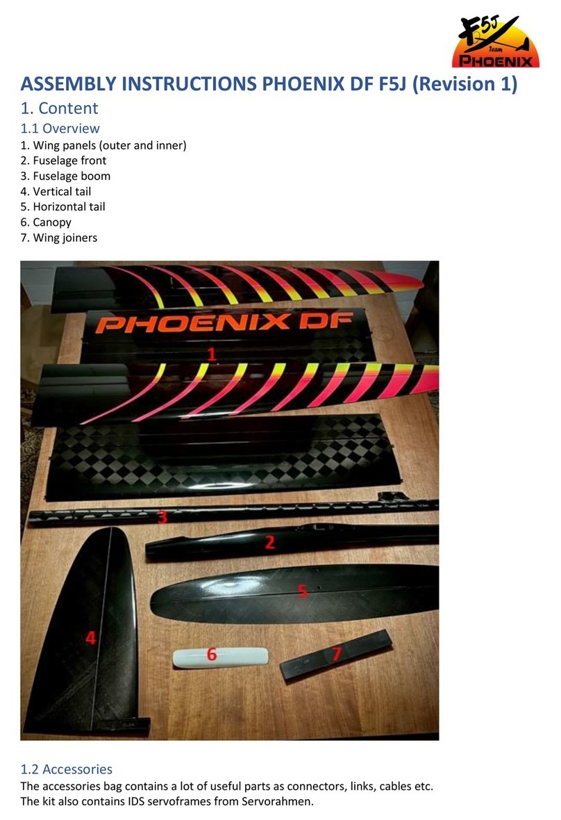
Phoenix

Phoenix R/C Aerobatic Glider Installation and operating instructions

Phoenix DF F5J User manual

Phoenix

Phoenix DF F5J User manual

Phoenix P51 mustang 60CC User manual

Phoenix

Phoenix P51 mustang 60CC User manual

Phoenix ask-21 electric 3200 User manual

Phoenix

Phoenix ask-21 electric 3200 User manual

Phoenix P40 WARHAWK User manual

Phoenix

Phoenix P40 WARHAWK User manual

Phoenix CAP 232 User manual

Phoenix

Phoenix CAP 232 User manual

Popular Toy manuals by other brands

GRAUPNER DANDY ARTF RC Assembly instructions

GRAUPNER

GRAUPNER DANDY ARTF RC Assembly instructions

Mattel HOT WHEELS Power Tower Track Set instructions

Mattel

Mattel HOT WHEELS Power Tower Track Set instructions

REVELL KIT 5527 Assembly manual

REVELL

REVELL KIT 5527 Assembly manual

Costway TY327901 user manual

Costway

Costway TY327901 user manual

Titan Dynamics Eagle user manual

Titan Dynamics

Titan Dynamics Eagle user manual

Eduard Me 262A Schwalbe quick start guide

Eduard

Eduard Me 262A Schwalbe quick start guide

Eduard US NAVY radar antennas WWII 1/350 STEEL quick start guide
Eduard

Eduard US NAVY radar antennas WWII 1/350 STEEL quick start guide

Carrera 10109 2,4 GHz WIRELESS Plus SET DUO Assembly and operating instructions

Carrera

Carrera 10109 2,4 GHz WIRELESS Plus SET DUO Assembly and operating instructions

Fisher-Price W9913 manual

Fisher-Price

Fisher-Price W9913 manual
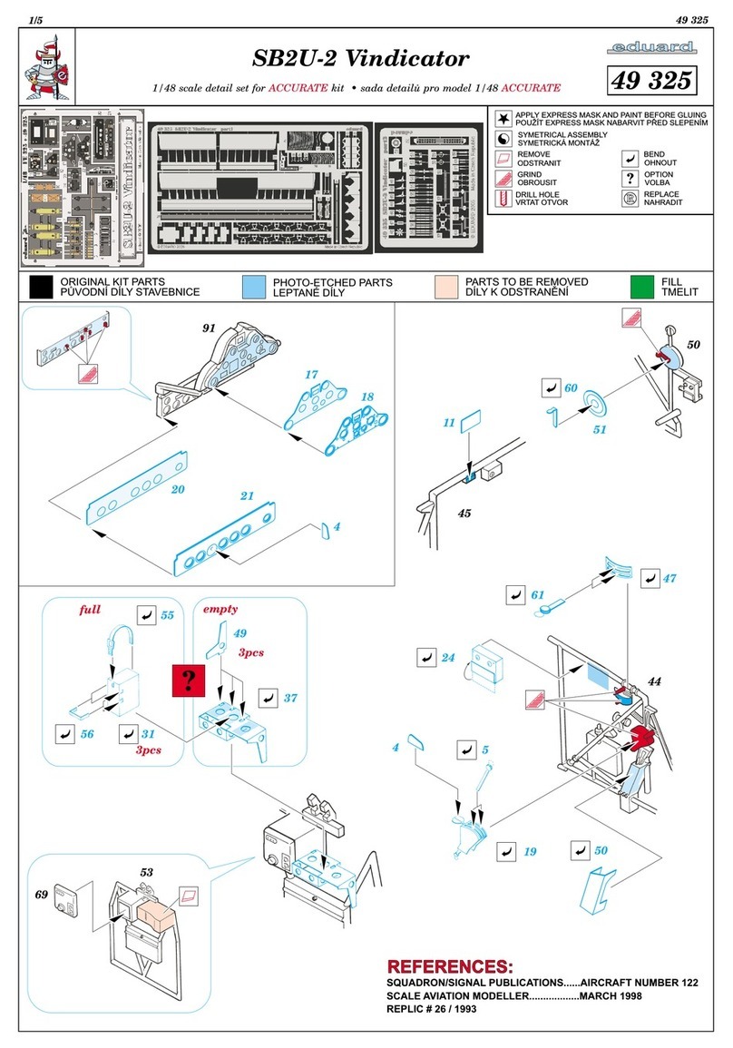
Eduard SB2 -2 Vindicator Assembly instructions

Eduard

Eduard SB2 -2 Vindicator Assembly instructions

LEGO 41119 manual

LEGO

LEGO 41119 manual

STAX 30820 Building Instruction

STAX

STAX 30820 Building Instruction

HobbyZone Apprentice S 2 1.2m Manual addendum

HobbyZone

HobbyZone Apprentice S 2 1.2m Manual addendum

Fisher-Price STRIDE-TO-RIDE WALKER 73499 instruction sheet

Fisher-Price

Fisher-Price STRIDE-TO-RIDE WALKER 73499 instruction sheet

Radio Flyer 3101A Assembly instructions

Radio Flyer

Radio Flyer 3101A Assembly instructions

marklin 37044 user manual

marklin

marklin 37044 user manual

Horizon Hobby BLADE Infusion 120 instruction manual
Horizon Hobby

Horizon Hobby BLADE Infusion 120 instruction manual

Eduard Tempest Mk.II quick start guide

Eduard

Eduard Tempest Mk.II quick start guide

manuals.online logo
manuals.online logoBrands
  • About & Mission
  • Contact us
  • Privacy Policy
  • Terms and Conditions

Copyright 2025 Manuals.Online. All Rights Reserved.