简体中文
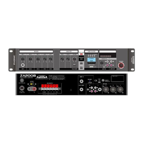
REAR PANEL
8. Input Amp Configuration Switches
These DIP switches have a number of different functions.
CH1 MicOn/LineOff
When set to Off, it allows line-level
signalinputthrough channel 1.When
set to On, it allows microphone-level
signals through channel 1.
CH1 Normal This switch sets channel 1 to
normal, with no priorities.
CH1 Priority
Enables muting of channels when
priority circuit on input 1 is closed.
Connect the priority connection on
Input 1 to microphone’s push-to-talk
function when this is activated.
CH1 VOX
Activating this switch allows
automatic muting when channel 1
input passes the preset threshold
(point 10).
CH1 to Zone 2
Activating this switch sends the
channel 1 input signal to the zone 2
output channel.
CH2 to Zone 2
Activating this switch sends the
channel 2 input signal to the zone
2 output.
CH3 to Zone 2
(CA35 and CA60 only)
Activating this switch sends the
channel 3 input signal to the zone
2 output.
CH2 PAD
(CA120 and CA240 only)
Activating this switch will reduce
the input signal level of channel 2
by 20 dB making it ideal for low-
impedance devices.
Phantom Power
Thisswitchactivatesphantom power
to the Input 1 input. Phantom power
is required for use with condenser
microphones.
9. Input 1 Terminal
This is a 5-pin Phoenix-type connection with 3 pins for balanced
input signals and 2 connectors for priority push-to-talk button
connection. The input accepts direct connection of line or
microphone inputs as selected by the mic/line DIP switch (point
8).
10. Input 1 VOX Threshold Control
This control adjusts the level at which the Input 1 signal should
be before other signals are muted. This only works when the
CH1 VOX DIP switch is turned on.
11. XLR Inputs (CA120 and CA240 only)
Channel 2 on the CA120 and CA240 offers users with an XLR
microphone input, ideal for input of microphones.
12. ¼” Inputs (CA120 and CA240 only)
The CA120 and CA240 offer unbalanced ¼” phone jack input
connectors input channels 2 through
13. 1/8” Mini-stereo Inputs (CA120 and CA240 only)
Channel 6 of the CA120 and CA240 also offers 1/8” mini-stereo
input connectors, similar to those used on laptops, iPods and
other MP3 players.
14. RCA Inputs
These inputs accept stereo unbalanced line-level RCA input
signals. The input signals received by these connectors are
summed.
15. Zone 2 / MOH Output and Control
This 4-pin Phoenix-type connector provides two different output
possibilities. The 8 ohm side is for 1W output to external speakers,
while the 600 ohm connectors are for connecting private branch
exchange (PBX) telephone systems for on-hold music. For
further info on wiring, see the Output Wiring section.
16. Preamp Output Terminal (CA35 and CA60 only)
This balanced 3-pin Phoenix type connection sends the CA35
and CA60 mixer/amplifier’s signal to external devices. The output
signal level is dependent on the master level control. For further
info on wiring, see the Output Wiring section.
17. Link Output (CA120 and CA 240)
This unbalanced ¼” phone jack output takes the pre-fader main
output signal of the amplifier to sent it to external devices.
18. Link Input (CA120 and CA240)
This unbalanced ¼” phone jack input allows users to incorporate
external signals directly into the CA120 and CA240’s main mix.
19. Amplifier Output
Speakers can be connected to this output terminal. Connections
available include COM (common), 70V, 100V and 8 ohms. These
input connections can accept terminal forks up to 10 AWG. For
further info on wiring, see the Output Wiring section.
20. Power Cable
The CA series’ has a preinstalled power cable. Please connect
the cable to a suitable AC power outlet. While the CA series
offers a universal power supply, be sure to check local voltage
levels before connecting the unit to ensure they correspond.
21. 24V Battery Input and Charging Switch (‘B’ models only)
These banana-plug input connectors
can be connected to the positive and
negative terminals of a 24V DC power
source. This allows the unit to function
even in the vent of power outages. The
switch located above these connections
is used to activated and deactivate the
charging circuit. It is advised not to leave
the battery in charge mode when already
fully charged.
21
89
1817
1314
10 11 12
1920

