Phonic WM400-L User manual

WM400-L / WM400D-L
WM400-R / WM400D-R
Wireless Receivers
English
User’s Manual

2WM 400-R / 400D-R / 400-L / 400D-L

3
WM 400-R / 400D-R / 400-L / 400D-L
INTRODUCTION........................................................................................................................................4
FEATURES...................................................................................................................................................4
PRODUCT DESCRIPTION......................................................................................................................5
WM-400(D) POWER MODES.................................................................................................................7
THE WM400D’S DIGITAL FEATURES.................................................................................................8
ATTACHING THE UNIT TO A SPEAKER.............................................................................................9
DIMENSIONS............................................................................................................................................10
SPECIFICATIONS....................................................................................................................................11
EQ PRESETS............................................................................................................................................12
WM400-L/WM400D-L
WM400-R/WM400D-R
Wireless Receivers
CONTENTS
Phonic reserves the right to improve or alter any information suppied within this document without prior notice.
V1.1 AUG 08, 2006

4WM 400-R / 400D-R / 400-L / 400D-L
INTRODUCTION
Congratulations on your purchase of the
WM400(D) wireless receiver, to be used
in conjunction with the WM60 or WM70
wireless transmitters. With either the stereo
or mono WM kits, you are now fast on your
way to becoming completely wireless in your
audio set up. The WM modules are not only
fantastic in style and convenience, however;
they are incredibly easy to use, as this
manual will no doubt prove.
Please have a thorough read of this user’s
manual before operating the WM modules.
Inside this guide you will nd information on
the ease of your wireless set up, as well as
some great troubleshooting tips and a com-
plete run-down on your modules’ features.
After reading, place the manual in an easy to
remember place so that you can come back
to it in future if ever necessary.
FEATURES
●
Working with the WM60 or WM70 trans-
mitter to form a wireless system for sav-
ing the audio cables between your mixer
and active speakers
●
Stand-alone UHF wireless receiver,
compatible with WM60 and WM70 trans-
mitters
●
12VDC external power supply (country
dependent)
●
16 user-selectable frequencies
●
RF carrier frequency range:
614.175 - 804.800 MHz (FCC)
614.175 - 864.800 MHz (CE)
●
Operating range: 210 ft. (70m, environ-
ment dependent)
●
Indicators for power on, AF and RF
●
Antenna: external, threaded connector
●
Audio output connectors: XLR out
●
M6, M8, M10 screws and Velcro strip
included for attaching WM400(D) to any
speakers
WM400D-L or WM400D-R plus:
●
300 ms digital delay processor for com-
pensation of different distance speakers
●
0.1 millisecond to 300.0 millisecond de-
lay range, delay adjustment may be
made with 0.1 millisecond precision
●
30 preset EQ curves and variable high
cut and low cut lters
●
4-digit display to indicate frequency
channel and delay, plus AF, RF and de-
lay bypass indicators

5
WM 400-R / 400D-R / 400-L / 400D-L
PRODUCT DESCRIPTION
These wireless receivers can be used in con-
junction with any active speaker. The receiver
can be attached to the speaker by screwing it
into the stand’s screw socket.
1. 4 Digit Display
(WM400D-L and WM400D-R only)
This display will allow users to see the
properties that are currently in use by
the WM400D, whether you are adjusting
the receiver channel (indicated by CH),
the EQ settings (indicated by EQ), the
delay time (indicated by only the delay
time in milliseconds) or the high and
low pass lters (indicated by a H or L,
respectively). When this unit is powered,
the 4 digit display will light up.
2. AF Indicators
When this LED is illuminated, it indicates
that there is an audio signal being
received by the WM400(D) receiver.
3. RF Indicators
When the RF indicator illuminates, it
shows that the transmitter’s signal is
being received successfully. If for some
reason this LED does not turn on, check
your DC power input and pre-set chan-
nel conguration and try again.
4. Bypass Indicator
(WM400D-L and WM400D-R only)
This LED will light up when the digital
processing feature of the WM400(D) re-
ceiver is off.
5. Power Button
hold this button down for 2 seconds to
power up the unit.
6. Bypass Button
(WM400D-L and WM400D-R only)
Push this button to turn the digital
processing feature on and off.
2
10
13
9
35
8
WM400
WM400D
1
4
567
13
10
2
3

6WM 400-R / 400D-R / 400-L / 400D-L
7. Up and Down Buttons
(WM400D-L and WM400D-R only)
These buttons are used to adjust the
properties of various features built-into
the WM400D’s. Pushing up or down will
initially simply allow users to adjust the
channel that the transmitter is using. If
you push both of these buttons at the
same time, it will jump to the next setting
that can be edited. You can then adjust
the properties by pushing the up and
down buttons. These settings will come
in the following order:
Channel Settings: CH 0 – CH 9,
CH A – CH F
Delay Settings: 0.0 – 300.0 milliseconds
EQ Mode: P1 – P30 (see the EQ table
for a full rundown on EQ presets)
Low Cut Filter: L 20 (Hz) – L 12 (kHz)
High Cut Filter: H 20 (kHz) – H 60 (Hz)
The high and low cut lters are adjusted in 1 Hz
increments; 10 Hz increments when over 1 kHz.
8. Channel Selector
(WM400-L and WM400-R only)
Adjusting this dial to one of the preset
channels allows the WM400 to know
which pre-set frequency to look for
the wireless information. The wireless
transmitter should be set to the identical
channel if transmission is to occur suc-
cessfully.
9. On Indicator
(WM400-L and WM400-R only)
This LED indicator illuminates when the
WM400(D) receiver is powered.
10. Antenna
This is the WM400(D)’s antenna. Adjust
it so it sits in a vertical position when the
device is in use (change the position if
the wireless signal quality is poor). Push
the antenna in to release it before ad-
justing its position.
WM400D
1
4
567
13
10
2
3
WM400
2
10
13
9
35
8
12
10
11
11. DC In and clip
Plug DC end of the supplied DC power
adaptor (12V, 200mA) into this jack, and
the other end into a suitable AC power
source to allow the WM400(D) to be
powered. The accompanying clip en-
sures the DC head of the power supply
is kept securely in place.
12. XLR Output
This jack accepts XLR connectors to
feed the signal from the Wireless Re-
ceiver to the Speaker.
13. Fixing
Use this hole to secure the WM400(D)
receiver into the mounting socket of your
speaker by use of the accompanying
M6, M8 or M10 screws and a washer.

7
WM 400-R / 400D-R / 400-L / 400D-L
WM400(D) POWER MODES
Since some users will mount their WM400(D)
with a speaker in a high position, Phonic
thought it would be handy to make it so us-
ers could keep the power on constantly, as
long as power is supplied to the unit and thus
avoiding having to climb up high to push the
power button. To make this adjustment, users
are advised to follow the follow procedure:
1. Remove the two screws on the rear of the
WM400(D) receiver and the antenna.
2. Remove the screw on the bottom of the
WM400(D) beside the XLR output (the
screw closer to the rear panel)
3. Remove the rear section of the casing by
gripping the WM400(D) on both sides,
squeezing and lifting up, in the process
detaching the small clips within the cas-
ing.
4. A small switch should be visible on the
PCB. Flick it to the left to ensure the power
of the WM400(D) does not turn off without
you pushing the power button.
5. Be sure to replace the casing and screws
before using the WM400(D) receiver.
Unscrew the antenna
Unscrew the two screws
located on the rear panel
Unscrew the screw on
just below the XLR jack
Move the switch to the left to ensure the
power i s always on. T o the right, the
power button will need to be pushed and
held down to turn the unit on.

8WM 400-R / 400D-R / 400-L / 400D-L
High Cut Filter
The high cut lter allows users to remove
unwanted high-frequency sounds, which can
help to remove high frequency hiss and feed-
back, as well as make the audio signal more
suitable for use with subwoofer speakers.
The high cut lter’s cut off frequency is ad-
justed in 1 Hz increments (10 Hz increments
over 1kHz) between 20 kHz and 60 Hz. The
default setting is 20 kHz.
Channel Mode
The channel number of the WM400D will be
displayed in the 4 digit display, unless ad-
justments are being made to other feature’s
properties. The channel number set should
match that of the WM60 or WM70 transmit-
ter to allow the wireless system to work suc-
cessfully.
Delay Mode
Changing the delay allows audio engineers to
compensate for the distance between speak-
ers on stage and audience members at the
rear of the venue. Using the delay effect on a
speaker at the rear will ensure the audio from
the stage reaches audience members at the
rear at approximately the same time as the
audio from the rear-speaker. The delay time
is adjusted in 0.1 millisecond increments, be-
tween 0 and 300 milliseconds (holding the up
or down button down speeds up the adjust-
ment time)
EQ Mode
The different EQ modes allow users to adjust
various frequencies of audio to enhance cer-
tain instruments, remove sibilance, feedback
and other undesirable noises, and improve
the overall delity of sounds. There are 30
presets to choose from (check EQ Preset
page for more information), the titles of which
describe what the effect does to your audio.
The default setting, P0, is completely at.
Low Cut Filter
A low cut lter allows users to cut low fre-
quency sounds, ensuring stage rumble and
other unwanted low-frequency sounds are
removed from your audio. This can also help
adjust the frequency to be more suitable for
use with tweeters. The low cut lter’s cut off
frequency is adjusted in 1 Hz increments (10
Hz increments over 1kHz) between 10 Hz
and 12 kHz. The default setting is 40 Hz.
THE WM400D’S DIGITAL FEATURES

9
WM 400-R / 400D-R / 400-L / 400D-L
ATTACHING THE UNIT TO A SPEAKER
Users can connect the WM400(D) Receiver modules to an active speaker using a mounting
point or the included velcro strips, as indicated.
Mounting Point Velcro Strip
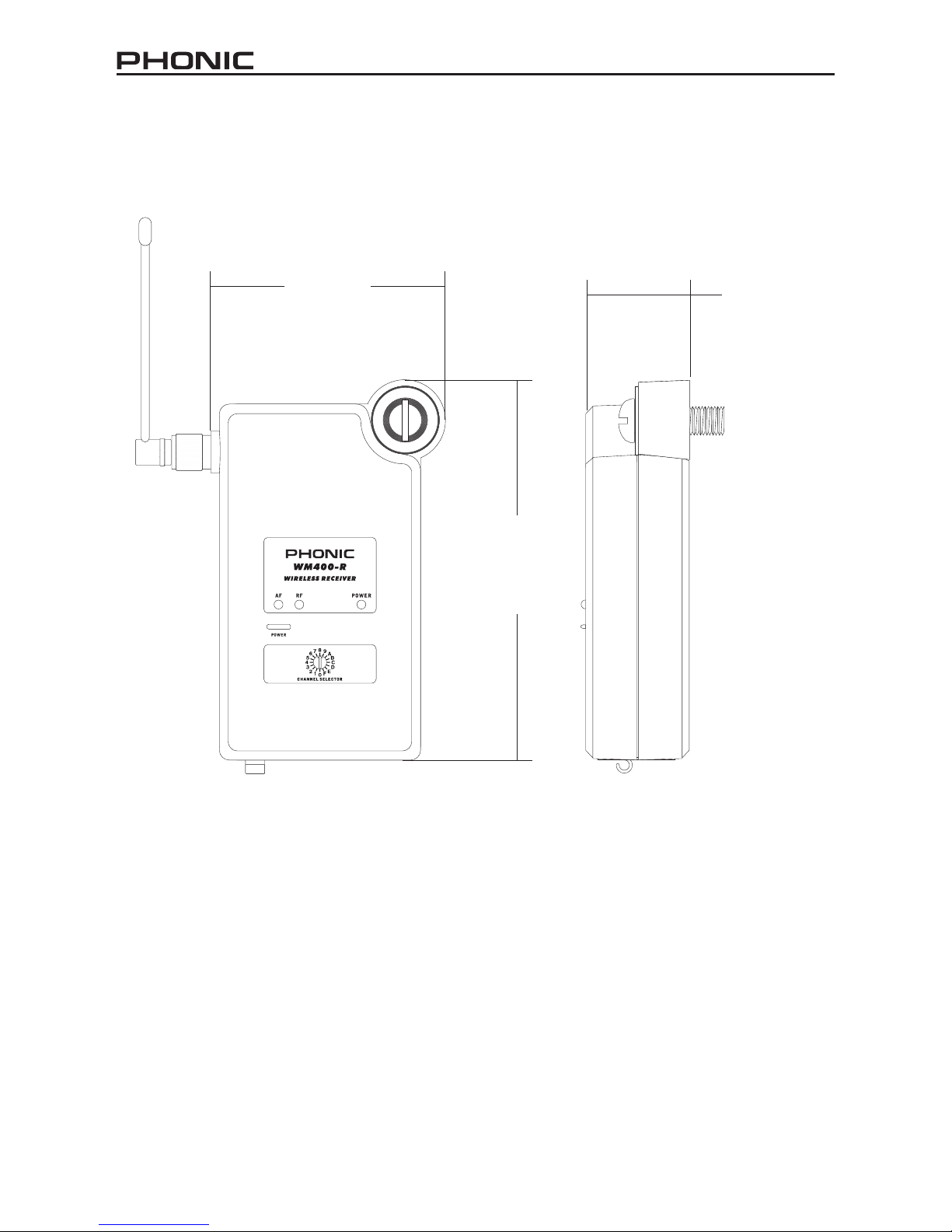
10 WM 400-R / 400D-R / 400-L / 400D-L
DIMENSIONS
* All measurements are shown in mm/inches.
79.25 / 3.1
128.35 / 5.1
35 / 1.4

11
WM 400-R / 400D-R / 400-L / 400D-L
SPECIFICATIONS
WM400-L / WM400-R
RF Sensitivity -100 dBm
Image Rejection 75dB
T.H.D. <0.5% @ 1KHz
LED indicator Power On, RF, AF
Squelch Pilot Tone & Noise Mute
Audio Output Connector XLR
Output Impedance 200Ω
Power Requirement 12VDC external power supply (country dependent)
Overall Dimensions (WxHxD) 88.5 x 133 x 36.7 mm (3.5” x 5.2” x 1.4”)
Net Weight 145 g (0.32 lbs)
WM400D-L / WM400D-R plus:
Digital Delay 0.1 millisecond to 300.0 millisecond delay range,
delay adjustment may be made with 0.1 millisecond
precision
Extra features 30 preset EQ, Low-cut and High-cut lter
Diplay 4-digit display for delay time, frequency channel, EQ
mode and Hi-cut/Lo-cut modes
Controls power on/off, Digital processing bypass, up and down

12 WM 400-R / 400D-R / 400-L / 400D-L
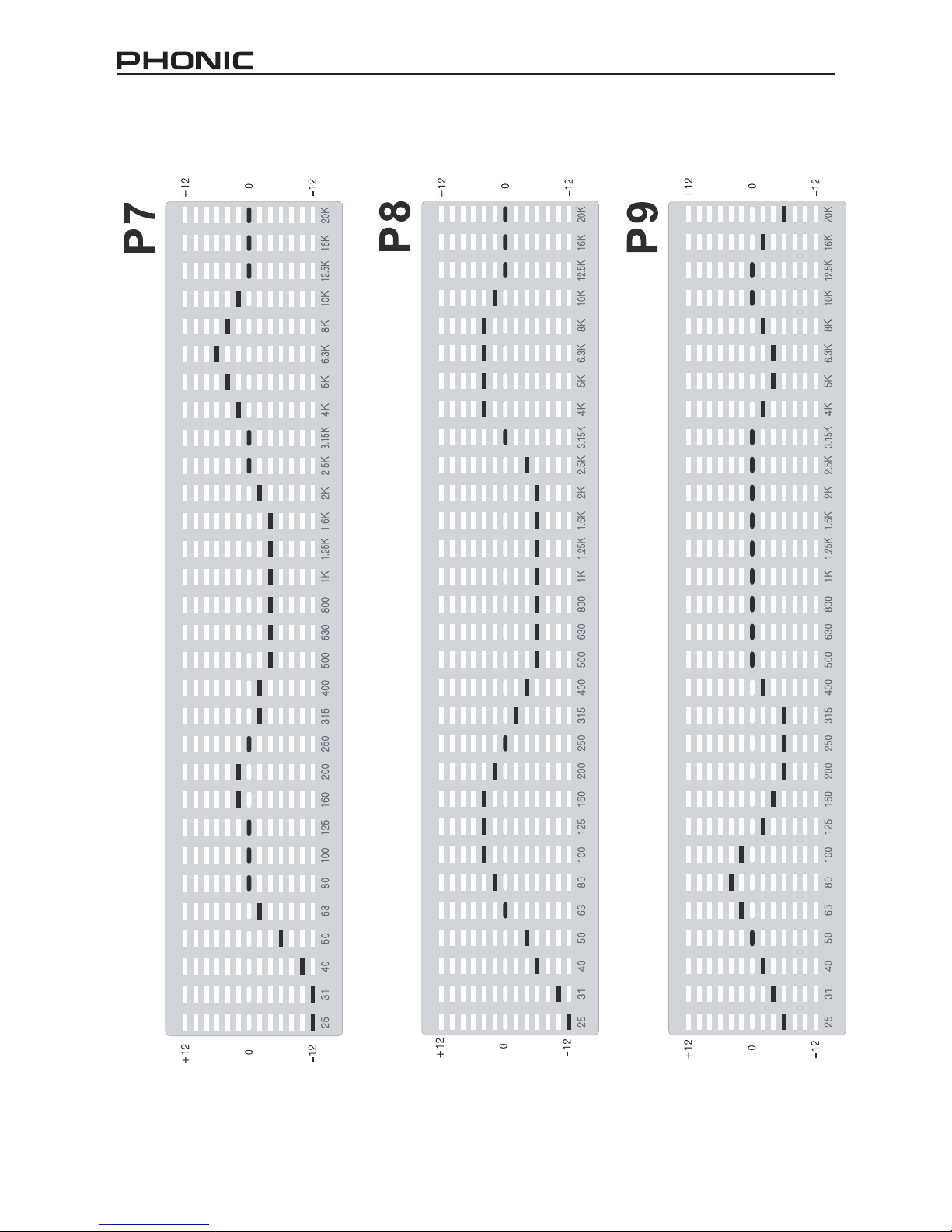
EQ PRESETS
Smooth
Speech
Darken

13
WM 400-R / 400D-R / 400-L / 400D-L
Warmth
Brighten
Smile
14 WM 400-R / 400D-R / 400-L / 400D-L
Vocal
Acoustic Guitar
Snare Drum

15
WM 400-R / 400D-R / 400-L / 400D-L
Techno
Loud
Telephone

16 WM 400-R / 400D-R / 400-L / 400D-L
Hum Reduction
Narrow Cut (80Hz)
Narrow Boost (800Hz)

17
WM 400-R / 400D-R / 400-L / 400D-L
Vinyl Warmth
Narrow Cut (8 kHz)
Narrow Cut (2.5 kHz)

18 WM 400-R / 400D-R / 400-L / 400D-L
Acoustic Guitar Air
Air Boost
Mini-TV

19
WM 400-R / 400D-R / 400-L / 400D-L
Tape Hiss Reduction
Bathtub
Cardboard Tube

20 WM 400-R / 400D-R / 400-L / 400D-L
Sizzle Cymbals
Rap Drums Hype
Electric Guitar Bandlimit
This manual suits for next models
3
Table of contents
Other Phonic Receiver manuals

Popular Receiver manuals by other brands


Spektrum
Spektrum SRS4210 instruction manual

Crystop
Crystop AUTOSAT 2 operating instructions

Xantech
Xantech HDRXSG01 installation instructions

Telcoma Automations
Telcoma Automations OC2 Series Operation and Programming Instructions

Meccanica Fadini
Meccanica Fadini Astro 40 quick start guide

RCA
RCA DXD406RD user guide