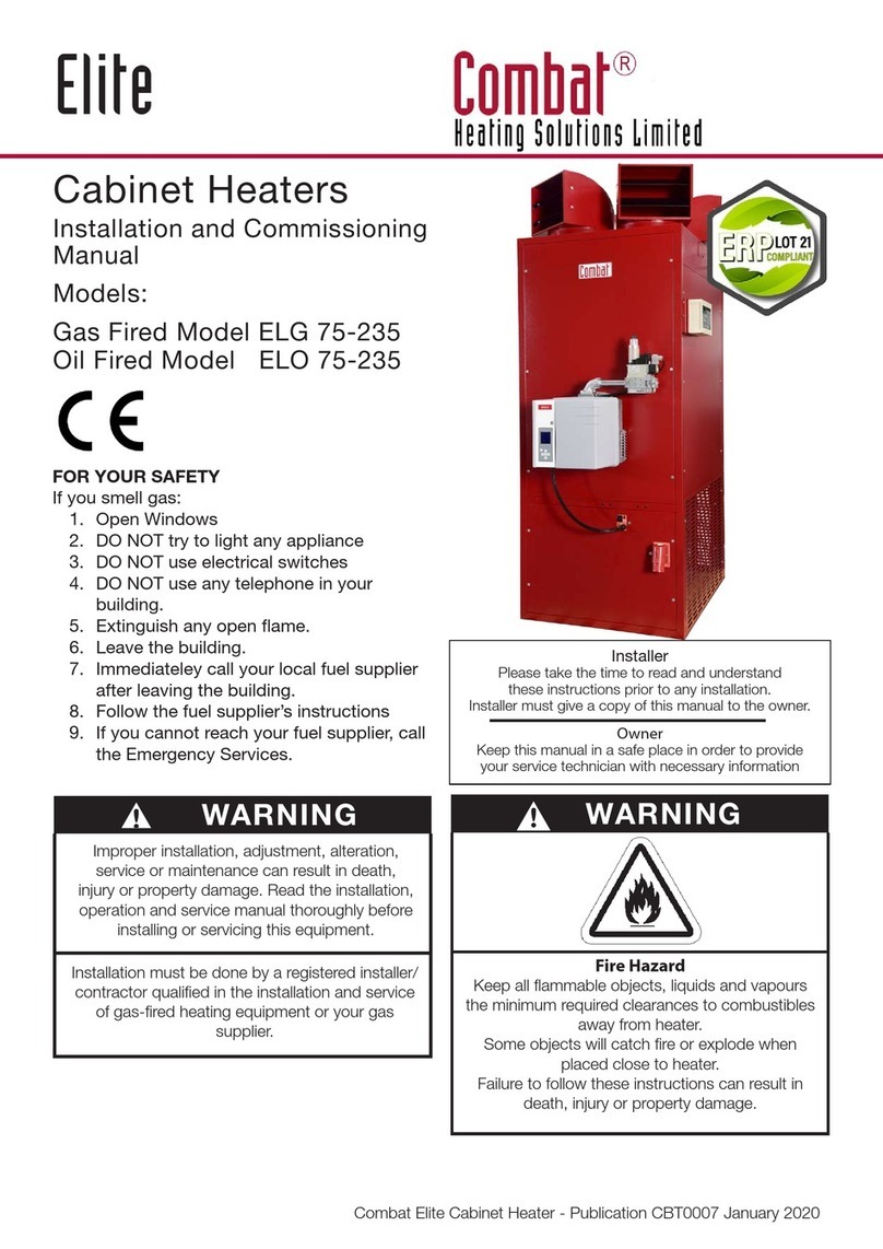
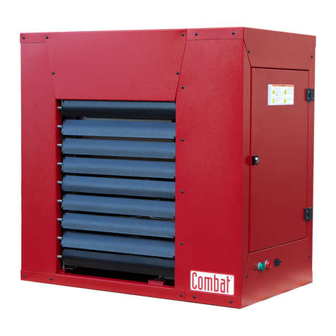
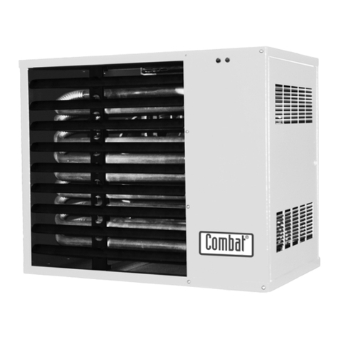
COMBAT CUHA Guide

SUITABLE FOR: GB, IE, IT & ES
UNIT HEATERS
Installation, Commissioning,
Service & User Instructions
Models
CUHA, CUHB, CUHC & CUHD
60 to 240 (Manual Ignition)
CUHA/A, CUHB/A, CUHC/A & CUHD/A
60 to 380 (Automatic Ignition)
October 1999
Part No. X404C
Price £5.00


Page 1
UNIT HEATER
These appliances have been tested and certified as complying with the
essential requirements of the Gas Appliance Directive, The Low Voltage
Directive, The Electromagnetic Compatibility Directive and the Machinery
Directive for use on natural gas and L.P.G. gas when installed, commissioned
and maintained in accordance with these instructions.
These instructions refer to appliances designed to operate in the following
countries:
Ireland (IE), Spain (ES), Italy (IT) & United Kingdom (GB ).
Appliances designed for other countries are available on request.
This Appliance must be installed in accordance with the rules in force and
used only in a sufficiently ventilated space, as specified in these instructions.
Before installation, check that the local distribution conditions, nature of gas
and pressure, and adjustment of the appliance are compatible.

Page 2
UNIT HEATER
CONTENTS
The parts of this manual are numbered by section, clause and sub-clause. Hence 1:2:3 refers to Section
1, clause 2, sub clause 3. Figure numbers also follow this notation, hence Fig.2:3 is Section 2, Fig. 3.
SECTION
1. General Specification
2. Technical Data
3. Heater Installation
4. Commissioning of theAir Heater
5. Wiring Diagram
6. Servicing Instructions
7. Removal and Replacement of Parts
8. Fault Finding Charts
9. User Instructions
10. Conversion between natural gas and L.P.G
11. Parts List
12. Commissioning Data Sheet
THESEAIR HEATERSARE FOR USEWITH NATURAL GAS OR L.P.G ONLYAS STATED
ON THE HEATER DATA PLATE (Conversion between gasses must be carried out in accordance with section
10 of these instructions)
THESE INSTRUCTIONS ARE TO BE LEFT WITH THE USER OR NEAR THE HEATER
Note: Everyeffort ismade to ensurethat theinformation contained in this Manual is accurate. However,
Combat Engineering Ltd. reserves the right to alter specifications without prior notice.
Combat shall not be liable to rectify any defects or damage caused by any modifications made or
attempted to be made to the heating units by the customer, his servants, agents or employees.
WARRANTY: The Heat Exchanger has a ten year Warranty (subject to terms and conditions).

Page 3
UNIT HEATER
Section 1. GENERAL SPECIFICATION- CUH RANGE
l.l Basic Information
There are eight types of heater in the CUH... range covered by these instructions.
1. CUHA 60 to CUHA 240 Manual ignition with axial fans.
(22.5kW (76770 Btu/hr) to 89kW (303668 Btu/hr) Gross heat input)
2. CUHB 60 to CUHB 240 Manual ignition with centrifugal fans.
(22.5kW (76770 Btu/hr) to 89kW (303668 Btu/hr) Gross heat input)
3. CUHC 60 to CUHC 240 Manual ignition as CUHB but with the fans encased to allow inlet ducting.
(22.5kW (76770 Btu/hr) to 89kW (303668 Btu/hr) Gross heat input)
4. CUHD 60 to CUHD 240 Manual ignition without fan for installing into ducting.
(22.5kW (76770 Btu/hr) to 89kW (303668 Btu/hr) Gross heat input)
5. CUHA/A 60 to CUHA/A 380 Automatic ignition axial fans.
(22.5kW (76770 Btu/hr) to 140kW (477680 Btu/hr) Gross heat input)
6. CUHB/A 60 to CUHB/A 380 Automatic ignition ,with centrifugal fans.
(22.5kW (76770 Btu/hr) to 140kW (477680 Btu/hr) Gross heat input)
7. CUHC/A 60 to CUHC/A 380 as CUHB/A but with the fans encased to allow inlet ducting.
(22.5kW (76770 Btu/hr) to 140kW (477680 Btu/hr) Gross heat input)
8. CUHD/A 60 to CUHD/A 380 Automatic ignition, without fans for installing into ducting .
(22.5kW (76770 Btu/hr) to 140kW (477680 Btu/hr) Gross heat input)
Combat CUH... ranges of unitAir Heaters are type B11 appliances for vertical flue which are designed
to be suspended or shelf mounted.
These heaters are Cat II 2H3+ appliances for use with natural gas or L.P.G. as stated on the heater data
plate, and are intended for indoor installation only.
They must be installed in accordance with local regulations and the requirements of Section 3 of these
Instructions.
A permanent electrical supply of 230 volts 50 Hz, single phase is required for all models and all
models must be earthed.
ON/OFF,temperature and time control may be obtained by useof the Combat range of controlconsoles,
or by the use of individual controls as per the circuit diagrams in Section 5.

Page 4
UNIT HEATER
1.2 Heater Operation
1.2.1 Automatic Ignition Burner
Combat CUH.../A range warm air heaters are fitted with an automatic ignition control which ignites
the gas and monitors for the safe operation of the burner each time the external controls call for the
heater to operate.
1.2.2 Manual Ignition
Combat CUH... range heaters are fitted with a permanent pilot which requires manual ignition. Once
ignited the pilot remains alight so long as the thermocouple is detecting a flame. i.e. the multifunctional
control or isolating gas valve is not turned off and the electrical power supply is not interrupted.
1.2.3 Common Operation - All Heater Types
When the external controls call for heat, the burner operates to supply heat to the heat exchanger.After
approximately 2 or 3 minutes the air delivery fan will start to run, supplying warm air to the building.
When the external controls are satisfied they will turn off the burner leaving the fan running to cool
down the heat exchanger. When cool enough the fan thermostat will turn off the fan.
Note: For CUHD... versions supplied without a fan, for installation in ducting with a customer supplied
fan unit, it is essential that the control of the fan incorporates a system for allowing the fan to run on at
close down of the burner as described above.
WARNING
The electrical isolator should only be used in an emergency and should not be used for
closing down the burner, as this switches off the fan prematurely and may damage the heat
exchanger invalidating the warranty and causing a potential fire hazard.
Operating the electrical isolator on a CUH... manual ignition heater will also
turn off the pilot burner.

Page 5
UNIT HEATER
Fig 2.1 Dimensions etc. CUHA... 60 to 300
Gas Connection Access to Second
Limit Thermostat
WARNING !
Isolate Before
Removing Cover
Electrical Connections
for Main Fan, Gas
Valve and Interrupter
Relay
Lighting
Instructions
Data Plate
Electrical Supply via Cable
Gland
Pilot viewing
via cut out
Combustion
Air Slots
Honeywell
Combination Fan/
Limit Stat.
Burner
Compartment Air Deflection
Grille
Model
Ref. 60 80 100 120 140 160 180 200 240 280 300
A Width mm
(ins) 519
(20½) 519
(20½) 589
(23) 589
(23) 729
(28½) 729
(28½) 869
(34) 869
(34) 1009
(39¾) 1219
(48) 1219
(48)
B Support
Spacing mm
(ins) 479
(18) 479
(18) 549
(21¾) 549
(21¾) 689
(27¼) 689
(27¼) 829
(32¾) 829
(32¾) 969
(38¼) 1179
(46½) 1179
(46½)
C Flue Dia. mm
(ins) 178
(7) 178
(7) 178
(7) 178
(7) 178
(7) 178
(7) 229
(9) 229
(9) 254
(10) 254
(10) 254
(10)
Weight kg 91 91 110 110 130 130 150 150 190 200 200

Page 6
UNIT HEATER
Fig 2.2 Dimensions etc. CUHA... 340 to 380
Air Deflection GrilleBurner Compartment
WARNING !
Isolate Before
Removing
Cover
Lighting
Instructions
Electrical Supply
via Cable Gland
Access to Second
Limit Thermostat
Combustion
Air Slots
Data Plate
Gas
Connection
Pilot viewing
via cut out
Electrical
Connections for
Main Fan, Gas
Valve and
Interrupter Relay
Flue
Connections
Assembled on Site
Honeywell
Combina-
tion Fan/
Limit Stat.
Model
Ref.
340
380
A Width mm
(ins) 1359
(53½) 1499
(59)
B Support
Spacing mm
(ins) 1319
(52) 1459
(59)
C Flue Dia. mm
(ins) 305
(12) 305
(12)
Weight kg 210 210

Page 7
UNIT HEATER
Fig 2.3 Dimensions etc. CUHB... 60 to 300
Burner
Compartment
Electrical Supply
via Cable Gland
Access to Second
Limit Thermostat
Data Plate
Combustion
Air Slots
Lighting
Instructions
Pilot viewing
via cut out Gas
Connection
Electrical
Connections for
Main Fan, Gas
Valve and
Interrupter Relay
WARNING !
Isolate Before
Removing
Cover
Honeywell
Combina-
tion Fan/
Limit Stat.
Air Deflection
Grille
Model
Ref. 60 80 100 120 140 160 180 200 240 280 300
A Width mm
(ins) 519
(20½) 519
(20½) 589
(23) 589
(23) 729
(28½) 729
(28½) 869
(34) 869
(34) 1009
(39¾) 1219
(48) 1219
(48)
B Support
Spacing mm
(ins) 479
(18) 479
(18) 549
(21¾) 549
(21¾) 689
(27¼) 689
(27¼) 829
(32¾) 829
(32¾) 969
(38¼) 1179
(46½) 1179
(46½)
C Flue Dia. mm
(ins) 178
(7) 178
(7) 178
(7) 178
(7) 178
(7) 178
(7) 229
(9) 229
(9) 254
(10) 254
(10) 254
(10)
Weight kg 111 111 130 130 150 150 170 180 220 270 270

Page 8
UNIT HEATER
Fig 2.4 Dimensions etc. CUHB... 340 to 380
Air Deflection GrilleBurner Compartment
Electrical
Supply via
Cable Gland
WARNING !
Isolate
Before
Removing
Cover
Combustion
Air Slots Access to Second
Limit Thermostat
Data
Plate
Lighting
Instructions
Gas
Connection
Pilot viewing
via cut out
Electrical
Connections for
Main Fan, Gas
Valve and
Interrupter Relay
Honeywell
Combina-
tion Fan/
Limit Stat.
Model
Ref.
340
380
A Width mm
(ins) 1359
(53½) 1499
(59)
B Support
Spacing mm
(ins) 1319
(52) 1459
(59)
C Flue Dia. mm
(ins) 305
(12) 305
(12)
Weight kg 276 276
Flue
Connections
Assembled on Site

Page 9
UNIT HEATER
Fig 2.5 Dimensions etc. CUHC... 60 to 300
Air Deflection
Grille
Burner
Compartment
WARNING !
Isolate
Before
Removing
Cover
Access to Second
Limit Thermostat
Combustion
Air Slots
Honeywell
Combina-
tion Fan/
Limit Stat. Electrical Supply via
Cable Gland
Lighting
Instructions
Data
Plate
Gas
Connection
Pilot viewing
via cut out
Electrical
Connections for
Main Fan, Gas
Valve and
Interrupter Relay
Model
Ref. 60 80 100 120 140 160 180 200 240 280 300
A Width mm
(ins) 519
(20½) 519
(20½) 589
(23) 589
(23) 729
(28½) 729
(28½) 869
(34) 869
(34) 1009
(39¾) 1219
(48) 1219
(48)
B Support
Spacing mm
(ins) 479
(18) 479
(18) 549
(21¾) 549
(21¾) 689
(27¼) 689
(27¼) 829
(32¾) 829
(32¾) 969
(38¼) 1179
(46½) 1179
(46½)
C Flue Dia. mm
(ins) 178
(7) 178
(7) 178
(7) 178
(7) 178
(7) 178
(7) 229
(9) 229
(9) 254
(10) 254
(10) 254
(10)
E Duct
Spigot Width mm
(ins) 438
(17¼) 438
(17¼) 508
(20) 508
(20) 648
(25½) 648
(25½) 788
(31) 788
(31) 928
(36½) 1137
(44¾) 1137
(44¾)
Weight kg 128 128 148 148 169 169 191 201 243 295 295

Page 10
UNIT HEATER
Fig 2.6 Dimensions etc. CUHC... Models 340 to 380 Range
WARNING !
Isolate
Before
Removing
Cover
Electrical Supply
via Cable Gland
Honeywell
Combina-
tion Fan/
Limit Stat.
Access to
Second
Limit
Thermostat
Combustion
Air Slots
Air Deflection GrilleBurner Compartment
Data
Plate
Lighting
Instructions
Gas
Connection
Pilot viewing
via cut out
Electrical
Connections
for Main Fan,
Gas Valve and
Interrupter
Relay
Model
Ref. 340 380
A Width mm
(ins) 1359
(53½) 1499
(59)
B Support
Spacing mm
(ins) 1319
(52) 1459
(59)
C Flue Dia. mm
(ins) 305
(12) 305
(12)
E Duct
Spigot Width mm
(ins) 1277
(50¼) 1417
(55¾)
Weight kg 303 304
Flue
Connections
Assembled
on Site

Page 11
UNIT HEATER
Fig 2.7 Dimensions etc. CUHD 60 to 300
Burner
Compartment 25mm Mez. Flange
Duct Connection Spigot
Electrical Supply via
Cable Gland
Honeywell
Combina-
tion Fan/
Limit Stat.
WARNING !
Isolate
Before
Removing
Cover
Combustion
Air Slots Access to Second
Limit Thermostat
Lighting
Instructions
Data
Plate
Pilot viewing
via cut out Gas
Connection
Electrical Connec-
tions for Gas Valve
and Interrupter
Relay
Rear Honeywell
Combination Fan/
Limit Stat.
Model
Ref. 60 80 100 120 140 160 180 200 240 280 300
A Width mm
(ins) 519
(20½) 519
(20½) 589
(23) 589
(23) 729
(28½) 729
(28½) 869
(34) 869
(34) 1009
(39¾) 1219
(48) 1219
(48)
B Support
Spacing mm
(ins) 479
(18) 479
(18) 549
(21¾) 549
(21¾) 689
(27¼) 689
(27¼) 829
(32¾) 829
(32¾) 969
(38¼) 1179
(46½) 1179
(46½)
C Flue Dia. mm
(ins) 178
(7) 178
(7) 178
(7) 178
(7) 178
(7) 178
(7) 229
(9) 229
(9) 254
(10) 254
(10) 254
(10)
D Duct
Spigot Width mm
(ins) 438
(17¼) 438
(17¼) 508
(20) 508
(20) 648
(25½) 648
(25½) 788
(31) 788
(31) 928
(36½) 1137
(44¾) 1137
(44¾)
Weight kg 82 82 92 99 104 114 124 134 154 180 180

Page 12
UNIT HEATER
Fig 2.7 Dimensions etc. CUHD 340 to 380
Access to Second Limit
Thermostat
Data
Plate
Lighting
Instructions
Honeywell
Combina-
tion Fan/
Limit Stat.
Combustion
Air Slots
WARNING !
Isolate
Before
Removing
Cover
Rear
Honeywell
Combination
Fan/Limit Stat.
Burner
Compartment 25mm Mez. Flange
Duct Connection Spigot
Gas
Connection
Pilot viewing
via cut out
Electrical
Connections
for Gas Valve and
interrupter relay
Electrical Supply
via Cable Gland
Model
Ref. 340 380
A Width mm
(ins) 1359
(53½) 1499
(59)
B Support
Spacing mm
(ins) 1319
(52) 1459
(59)
C Flue Dia. mm
(ins) 305
(12) 305
(12)
D Duct
Spigot Width mm
(ins) 1277
(50¼) 1417
(55¾)
Weight kg 190 190
Flue
Connections
Assembled
on Site

Page 13
UNIT HEATER
Table 2.1 General Technical Data - All Models
ECNEREFERLEDOM0608001021041061081002042082003043083
EGNAR'A'
-daoLlacirtcelElatoT
sttaW 1911911918.7228.7224444442.4832.4838.8488.8488.8488.848
epyTnaF nafiSnafiSnafiSnafiSnafiSnafiSnafiSnafiSnafiSnafiSnafiSnafiSnafiS
GMPGMPGMPGMPGMPGMPGMPGMPGMPGMPGMPGMPGMP
101-14053101-14053101-14053101-14093101-14093101-14024101-14024101-14053101-14053101-14024101-14024101-14024101-14024
dettiFsnaFforebmuN 1111111222222
fµroticapaC 5.25.25.23344 5.2x25.2x24x24x24x24x2
sttaW-gnitaR 071071071012012081081071071081081081081
spmA-tnerruCnuR 7.07.07.068.068.08.18.145.145.165.365.365.365.3
spmA-tnerruCtratS 9.19.19.13.23.24.34.32.42.47.67.67.67.6
rh/³M-wolFriA 0962096200330283440460743834065405360139013967396739
nim/³tf-wolFriA 3851385124918422083207720852486273730845084591559155
gk-thgieW 1919011011031031051051091002002012012
SEGNAR'C'&'B'
-daoLlacirtcelElatoT
sttaW 00900900210021571157110571002200420042004200530053
dettiFsnaFforebmuN FFO1FFO1FFO1FFO1FFO1FFO1FFO2FFO2FFO2FFO2FFO2FFO3FFO3
epyTnaF 072-072NIROT072-072NIROT072-072NIROT072-072NIROT072-072NIROT072-072NIROT142-142NIROT142-142NIROT072-072NIROT072-072NIROT072-072NIROT072-072NIROT072-072NIROT
TCERID
EVIRD
TCERID
EVIRD
TCERID
EVIRD
TCERID
EVIRD
TCERID
EVIRD
TCERID
EVIRD
EVIRDTCERIDEVIRDTCERID
TCERID
EVIRD
TCERID
EVIRD
TCERID
EVIRD
TCERID
EVIRD
TCERID
EVIRD
sliateDrotoM
sttaWeziS 055x1055x1055x1055x1055x1055x1055x2055x2055x2055x2055x2055x3055x3
DEEPSTESLAMRON WOLWOLMUIDEMMUIDEMMUIDEMMUIDEMWOLMUIDEMMUIDEMMUIDEMMUIDEMMUIDEMMUIDEM
-tnerruCnuRlamroN
spmA 9.39.32.52.51.51.55.74.93.013.013.015151
-tnerruCtratSlamroN
spmA 8.48.44.64.6663.96.118.21277.21277.216.816.81
deepShgiHtasmumixaM
spmA-tnerruCnuR 1.61.69.69.61.51.54.114.117.317.317.319.719.71
spmA-tnerruCtratS 88 6.86.877 6.316.311.711.711.711.221.22
tuohtiwdesuebottoN tabmoCotecnerefer
rh/³M-wolFriA 0052006200130023052306230844007500260076008600490049
nim/³tf-wolFriA 1741035152813881319191917362553394633493200433553355
gkthgieW-egnaR'B' 111111031031051051071081022072072672672
gkthgieW-egnaR'C' 131131051051071071591502542003003603603
EGNAR'D'
deriuqeR
rh/³mwolFriAmuminiM 0052006200130023052306233834065400260086008667396739
nim/³tf 1741035152813881319191910852486294632004200491559155
taehssorcassolerusserP
riaderiuqertaregnahcxe
wolf
rabm 34.034.034.034.034.034.034.034.034.034.034.034.034.0
gkthgieW-egnaR'D' 28282999401411421431451081081002022
eziSnoitcennoCsaG
egnaRnoitingIlaunaM ½R½R½R½R½R½R½R½R½RA/NA/NA/NA/N
egnaRnoitingIcitamotuA ½R½R½R½R

Page 14
UNIT HEATER
Table 2.2 Technical Data CUHA, CUHB, CUHC and CUHD
Manual Ignition Range
Appliance Category II2H3+ Propane Gas Inlet pressure 37 mbar (25 - 45)
Natural gas inlet pressure 20 mbar (17 - 25) Butane gas Inlet pressure 29 mbar (20 - 35)
ONLEDOMNOITINGILAUNAM0608001021041061081002042
Wk-vcssorGtupnItaeH 5.225.92733425955.664798
rh/utB-vcssorGtupnItaeH 07767456001442621617641424771803102898622884252866303
Wk-vcteNtupnItaeH 3.026.623.337.839.642.359.957.662.08
rh/utB-vcteNtupnItaeH 0719698609647311191231958951973181534402294722506372
Wk-tuptuOtaeH.xorppA 87.7113.3232.9279.3380.1416.6445.2564.8513.07
rh/utB-tuptuOtaeHxorppA 846067159733799609511561041330951942971664991898932
srenruBforebmuN 4456789 0121
SAGLARUTAN
ezisrotcejnI 49.x749.x749.x749.x749.x749.x749.x749.x749.x7
kramdna 048048048048048048048048048
rabm-erusserPrenruB 9.5016.017.0121215.218.219.41
GWsni-erusserPrenruB 4.242.43.48.48.40.51.50.6
rh/³M-etaRsaG 41.218.235.301.469.426.543.650.784.8
rh/³tf-etaRsaG 7.573.995.4217.4410.5715.8918.3220.9425.992
EPYTEVLAVSAG avoN.T.I.SavoN.T.I.SavoN.T.I.SavoN.T.I.SavoN.T.I.SavoN.T.I.SavoN.T.I.SavoN.T.I.SavoN.T.I.S
450.028.0450.028.0450.028.0450.028.0450.028.0450.028.0450.028.0450.028.0450.028.0
oNTRAP 134L134L134L134L134L134L134L134L134L
SAGGPL
eziSrotcejnI A/N45.x745.x745.x745.x745.x745.x745.x745.x7
kramdna A/N052052052052052052052052
rabm-erusserPtelnIenaporP A/N7300.737300.737300.737373
GWsnI-erusserPtelnIenaporP A/N8.4108.418.4108.418.4108.418.418.41
rh/³MetaRsaGenaporP A/N11.193.126.169.122.205.297.253.3
rh/gketaRsaGenaporP A/N11.246.270.327.322.457.492.563.6
rabm-erusserPtelnIenatuB A/N9200.929200.929200.929292
GWsnI-erusserPtelnIenatuB A/N6.1106.116.1106.116.1106.116.116.11
rh/³MetaRsaGenatuB A/N48.060.132.194.196.109.121.255.2
rh/gketaRsaGenatuB A/N51.296.231.387.392.448.493.584.6
EPYTEVLAVSAG A/NavoN.T.I.SavoN.T.I.SavoN.T.I.SavoN.T.I.SavoN.T.I.SavoN.T.I.SavoN.T.I.SavoN.T.I.S
A/N450.028.0450.028.0450.028.0450.028.0450.028.0450.028.0450.028.0450.028.0
)ROTALUGERON()ROTALUGERON()ROTALUGERON()ROTALUGERON()ROTALUGERON()ROTALUGERON()ROTALUGERON()ROTALUGERON(
oNTRAP 134L134L134L134L134L134L134L134L

Page 15
UNIT HEATER
Table 2.3 Technical Data CUHA/A, CUHB/A, CUHC/A and CUHD/A
Automatic Ignition Range
Appliance Category II2H3+ Propane Gas Inlet pressure 37 mbar (25 - 45)
Natural gas inlet pressure 20 mbar (17 - 25) Butane gas Inlet pressure 29 mbar (20 - 35)
NOITINGICITAMOTUA ECNEREFERLEDOM 06A/08A/001A/021A/041A/061A/081A/002A/042A/082A003A/043A/083A/
Wk-vcssorGtupnItaeH 5.225.92733425955.664798301011521041
rh/utB-vcssorGtupnItaeH 07767456001442621617641424771803102898622884252866303634153023573005624086774
Wk-vcteNtupnItaeH 3.026.623.337.839.642.359.957.662.088.291.996.2111.621
rh/utB-vcteNtupnItaeH 0719698609647311191231958951973181534402294722506372446613361833772483093034
Wk-tuptuOtaeH.xorppA 87.7113.3232.9279.3380.1416.6445.2564.8513.0773.1809.6857.8906.011
rh/utB-tuptuOtaeH.xorppA 846067159733799609511561041330951942971664991898932436772305692539633763773
srenruBforebmuN 4456789 012141517191
SAGLARUTAN
ezisrotcejnI 49.x749.x749.x749.x749.x749.x749.x749.x749.x749.x749.x749.x749.x7
kramdna 048048048048048048048048048048048048048
rabm-erusserPrenruB 7.56.92.01016.015.015.015.015.015.015.010.114.11
3.28.31.40.42.42.42.42.42.42.42.44.46.4
rh/³M-etaRsaG 41.218.235.301.469.426.543.650.784.818.984.0119.1143.31
rh/³tf-etaRsaG 7.573.995.4217.4410.5715.8918.3220.9425.9926.6432.0736.0241.174
EPYTEVLAVSAG .T.I.S.T.I.S.T.I.S.T.I.S.T.I.ST.I.ST.I.ST.I.ST.I.ST.I.ST.I.SnosnhoJnosnhoJ
mednaTmednaTmednaTmednaTmednaTavoNavoNavoNavoNavoNavoN 0402MG
1009 0402MG
1009
330.038.0330.038.0330.038.0330.038.0330.038.0711-228-0711-228-0711-228-0711-228-0711-228-0711-228-0
oNTRAP 114L114L114L114L114L124L124L124L124L124L124L950L950L
SAGGPL
eziSrotcejnI A/Nmm45.0x7mm45.0x7mm45.0x7mm45.0x7mm45.0x7mm45.0x7mm45.0x7mm45.0x7mm45.0x7mm45.0x7mm45.0x7mm45.0x7
kramdna A/N052052052052052052052052052052052052
ENAPORP
rabm-erusserPtelnI A/N737373737373737373737373
GWsnI-erusserPtelnI A/N8.418.418.418.418.418.418.418.418.418.418.418.41
rh/³M-etaRenaporP A/N11.193.126.169.122.205.297.253.388.341.407.472.5
rh/gk-etaRenaporP A/N11.246.270.327.322.457.492.563.663.768.739.810.01
rh/rtLdiuqiL-etaRenaporP A/N1.42.50.63.73.83.94.014.214.414.515.716.91
ENATUB
rabm-erusserPtelnI A/N929292929292929292929292
GWsnI-erusserPtelnI A/N6.116.116.116.116.116.116.116.116.116.116.116.11
rh/³M-etaRenatuB A/N48.060.132.194.196.109.121.255.259.251.385.310.4
rh/gk-etaRenatuB A/N51.296.231.387.392.448.493.584.605.700.801.991.01
rh/rtLdiuqiL-etaRenatuB A/N47.396.454.506.684.734.893.992.1160.3159.3168.5167.71
EPYTEVLAVSAG T.I.ST.I.ST.I.ST.I.ST.I.S
A/NmednaTmednaTmednaTmednaTavoN.T.I.SavoN.T.I.SavoN.T.I.SavoN.T.I.SavoN.T.I.SavoN.T.I.SnosnhoJnosnhoJ
020.038.0020.038.0020.038.0020.038.0711-228-0711-228-0711-228-0711-228-0711-228-0711-228-00402MG
1009
0402MG
1009
oN(
)rotalugeR
oN(
)rotalugeR
oN(
)rotalugeR
oN(
)rotalugeR
oN(
)rotalugeR
oN(
)rotalugeR
oN(
)rotalugeR
oN(
)rotalugeR
oN(
)rotalugeR
oN(
)rotalugeR
oN(
)rotalugeR
oN(
)rotalugeR
oNTRAP 314L314L314L314L124L124L124L124L124L124L950L950L

Page 16
UNIT HEATER
2.1 Gas Controls - Automatic Ignition
The heaters may be fitted with one of two types of gas control valves dependent upon the model, each
giving the same control elements as follows (see Section 4).
2.1.1 Main Gas Burner
The multifunctional main gas valve contains a gas regulator and two automatic shut off valves.When
set up as defined in Section 4 the valves will have a step opening operation on the main gas to give
smooth lighting. Settings of the valves are given in Section 4 and tables in Section 2.
2.1.2 Start Gas Burner
There is one solenoid valve to control the pilot burner gas supply which is designed to operate at inlet
pressure and therefore does not need a regulator.
2.2 Gas Controls - Manual Ignition
The multifunctional gas valve contains a main gas regulator, a safety gas valve controlled by the
thermocouple, and a solenoid valve to operate the main gas.
The manual control knob and Piezo electric igniter incorporated in this control allow for the safe
manual ignition of the pilot and selection for automatic operation of the main burner.
2.3 Main Fan
The main air moving fan(s) fitted to these heaters are operated automatically by the fan thermostat
within the Honeywell combination fan/limit thermostat. When suitably connected to site wiring (see
Section 5) the fan(s) may also be used for distributing unheated air.
2.4 Limit Thermostats
There are two limit thermostats on these heaters to protect them from overheating, should the fan fail
for any reason. One is within the Honeywell combination thermostat and the second is situated on the
side of the heater towards the rear. Note: on models 340 and 380 B & C versions there is an extra
secondary limit thermostat protecting the third fan unit.
2.4.1 Honeywell Combination Fan/Limit Thermostat
The combination fan/limit thermostat is a dual function control and safety device (see Fig. 2.7).There
are two of these fitted to CUHD versions, the second one on the inlet spigot at the rear of the heater.

Page 17
UNIT HEATER
2.4.2 Second Limit Thermostat
This is a manual reset device - see Figs. 2. 1 to 2.7.
Note: On CUHB and CUHC models 340 and 380 there are two of these fitted.
To reset this thermostat:
a) Remove the screw on cover of the thermostat where it protrudes from the cabinet side.
b) Push in the button in the centre of the thermostat. Note: the heat exchanger must be cooled to
allow this to happen.
c) Replace the cover.
Fan Thermostat
The fan thermostat controls the operation of the main fan during the heater operating cycle. This
control also ensures that the main fan continues to run after the burner turns off to dissipate the residual
heat from the heat exchanger.
The white button on the fan thermostat should be pulled to its “out” position for normal operation. In
the “pushed in” position the fan will run continuously. However, when connected to CD100 type
control consoles this feature is catered for by the fan on position of the control switch.
Limit Thermostat
The limit thermostat operates in overheat conditions caused by insufficient air passing over the heat
exchanger.Thisis amanualreset device and is reset bypressingin theredreset button on thethermostat.
Note the heat exchanger must have cooled to below the operating temperature for reset to be possible.
Fig. 2.8 Combination Fan/Limit Thermostat
WARNING: IT IS ESSENTIAL THAT THE BREAK OFF LINK SHOWN IS REMOVED
IN THE EVENT OF THERMOSTAT REPLACEMENT

Page 18
UNIT HEATER
2.5 Thermocouple Interrupter Relay
All manual ignition heaters are fitted with a thermocouple interrupter relay to interface between the
limit thermostats and the thermocouple. This relay is fully encapsulated and if faultymustbe replaced
with the same type as it is specially produced to operate with burner thermocouples.
For normal operation the limit thermostats provide a constant voltage to the coil connections making
therelaypermanentlyenergised unlessthe limit thermostatsoperate or the electrical supply is interrupted.
In the event of interruption of the electrical supply to the interrupter relay then the contact opens and
the safety valve of the multifunctional gas valve closes. The pilot will then need to be manually relit.
2.6 Automatic Ignition - Burner Control Box
2.6.1 DESCRIPTION OF SATRONIC TFI 812 2B Mod 10 CONTROL BOX
The fully automatic gas burner fitted to all CUHA/A, CUHB/A, CUHC/A and CUHD/A models is
controlled by a Satronic TFI 812 2B Mod 10 plug-in control box. This control ensures the safe start
and stop sequence and also monitors the safe presence of a flame.
Fig 2.9 Satronic TFI 812 Control Box Sequence
This manual suits for next models
7
Table of contents
Other COMBAT Heater manuals