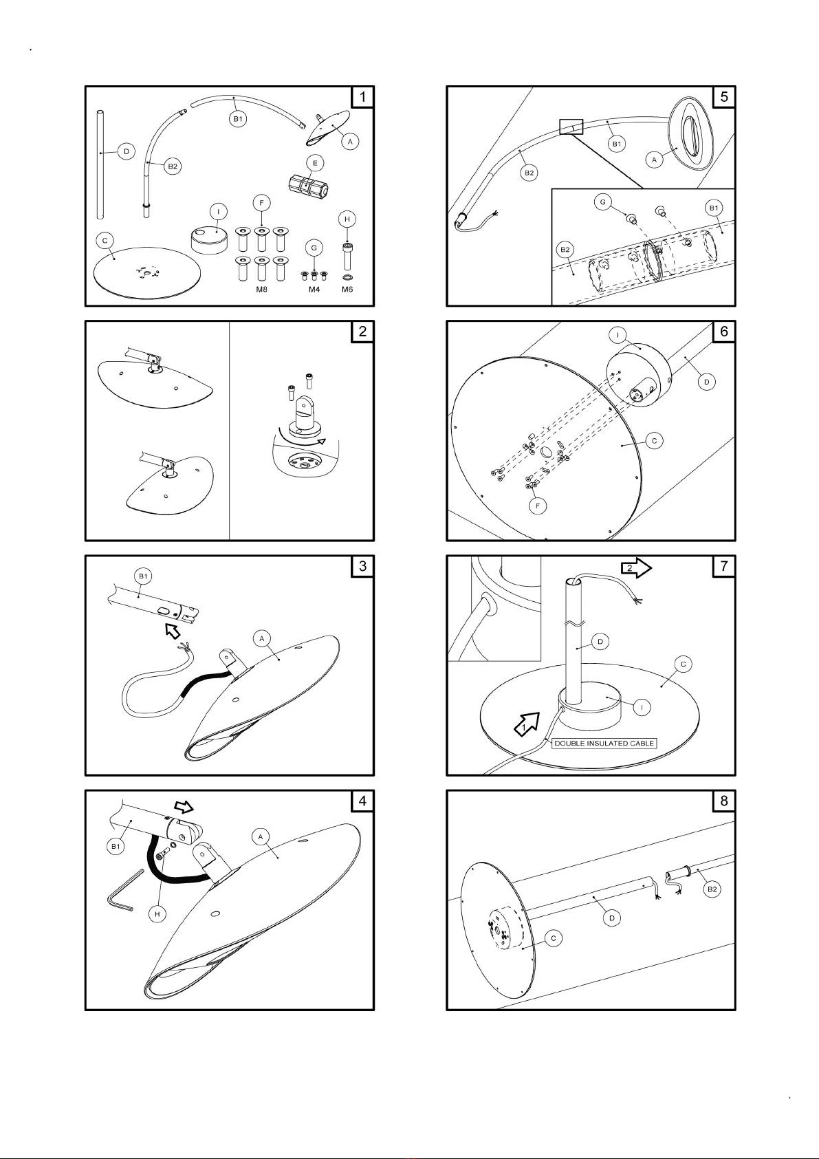
D. Tube de base
E. Raccord pour câbles électriques
F. Six vis M8
G. Trois vis M4
H. Une vis M6 avec rondelle
I. Contrepoids pour la base C
2. Choisir l'orientation l'appareil chauffant: il peut être installé en position longitudinale ou
transversal, en desserrant les deux vis M6 qui fixent la connexion supérieure de la lampe et en
tournant la même connexion de 90°. Il faut soigner de ne pas tordre le câble d'alimentation et visser
la rotule tournante dans la nouvelle position avec les mêmes vis.
3. . Insérer l'extrémité libre du câble électrique de la lampe A, dans la fente d'entrée du tube de
support B1 et faire le glisser à l'intérieur, jusqu'à que à dans la fente s’insère également la gaine en
silicone qui sorte de la lampe (une triple protection du câble d'alimentation.
4. Fixer la lampe A à l'extrémité du tube de support B1, en serrant la vis H. a vis doit être vissée
avec la spéciale rondelle en dotation. À la fin du montage la vis doit être serrées de sorte que la
lampe ne puisse pas accidentellement pivoter et donc surchauffer murs, éléments potentiellement
inflammables, ou prises de courant.
5. e câble doit être complètement extrait de l'autre côté du tuyau B1. Ensuite insérer le câble dans
le tuyau B2 et l’extraire complétement de l’autre côté. Enfin il faut fixer les tuyaux B1 et B2 par les
deux vis G.
6. En tenant les pièces sur une carton ou une surface anti-égratignure, fixer le tube D et le
contrepoids I à la base, en serrant avec force les six vis longues F fournies dans le paquet, en
plaçant la fente du tuyau D vers l'arrière de la base, comme indiqué de la figure.
7. Insérer le câble d'alimentation provenant de la plante électrique, dans la fente à la base du tube
D , jusqu'à qu'il ressorte de l'autre côté au moins 20/30 cm.
Attention: de la plant électrique doit toujours arriver un câble à double
isolation (avec section de 3x1.5 mm2) type HAR et avec 6-9 mm de diamètre,
afin d'éviter tout risque de mettre sous tension les parties métalliques de
l'attaque. Dans le cas où le câble en provenance de la plante n'est pas à
double isolation, il faut le changer avant le montage de la lampe.
8. Approcher la base, avec le tube monté sur celle-ci (C+D+I), au tube de lampe (B1+B2+A) et
couper les câbles électriques d'une longueur suffisante pour la connexion des câbles..
9. Connecter les deux câbles avec le raccord d’étanchéité, en suivant les instructions contenues
dans le paquet et soigner de coupler phase avec phase, neutre avec neutre, et terre avec terre.
Serrer les boulons de pour assurer l'intégrité de l'étanchéité des câbles.
10. Faire glisser le raccord à l’intérieur du tube D (vers la base) pour 20/30cm. Enfin, insérer le tube
B1+B2 avec la lampe, dans le tube de base et le fixer avec la vis G.
11. Positionner la tige en vertical et orienter la lampe dans la direction choisie, et serrer
définitivement la vis H.
12. a lampe Hotdoor est maintenant assemblée et prêt à l'emploi. Dans le cas où on souhaite fixer
la lampe au sol avec une vis tamponnées, utiliser le trou de la base pour insérer la vis.
AVERTISSEMENT: en cas d'utilisation à l'extérieur, appliquez toujours propres connexions
étanches pour câbles électriques (fig. A)
DE - MONTAGEANWEISUNGEN
Montage des Heizstrahlers Hotdoor®
mit einzelnem Ständer HC 01
Achtung: der Heizstrahler Hotdoor muss in einem Sicherheitsabstand von Mauern, Wänden,
oder entflammbaren Gegenständen montiert oder gerichtet werden. itte folgen Sie
aufmerksam die edienungsanleitung des Heizstrahlers Hotdoor.
1. ieferumfang:
A. Heizstrahler Hotdoor
B. Stützröhre B1 + B2
C. Fuβ
D. Fuβrohr
E. Verbindung für Stromkabel
F. Sechs Schrauben M8
G. Drei Schrauben M4
H. Eine Schraube M6 mit Scheibe
I. Gegengewicht für dem Fuß C
2. Wählen Sie die Stellung des Gerätes: das Gerät kann sowohl in longitudinaler als auch in
transversaler Stellung auf diese Weise installiert werden: lösen Sie die zwei Schrauben M6, die die
obere Kopplung an dem Strahler befestigen, und drehen Sie die selbe Kopplung von 90°, dabei
geben Sie acht, dass Sie das Stromkabel nicht biegen; danach befestigen Sie die Kopplung in der
neuen Stellung mit den selben Schrauben wieder.
3. Stecken Sie das freie Ende des Stromkabels, das aus der ampe A kommt, in den dafür
vorgesehenen Schlitz des Stützrohrs B1 ein, und lassen es hinein schieben, bis auch die Silikon
Hülse, die aus der ampe kommt, in den Schlitz hineingeht (dreifacher Schutz des Stromkabels).
4. Befestigen Sie den Strahler A am Ende des Stützrohr B durch das Anziehen der Schraube H. Die
Schraube muss mit der belieferten gerändelten Scheibe montiert werden. Am Ende der Montage soll
die Schraube gut angezogen werden, damit die ampe nicht zufällig drehen kann und die Wände,
brennbare Gegenstände oder Steckdosen überhitzen kann
5. Das Kabel muss aus der anderen Seite des Rohrs völlig herausgezogen werden. Das Kabel in
dem Stützrohr B2 einstecken und dann von dem gegenteiligen Ende es herausziehen. Dann müssen
die Stützrohre B1 und B2 durch den zwei Schrauben G befestigt werden.
6. Die Teile auf einen Karton oder auf einen Schütz gegen Kratzer legen und das Gegengewicht I
und das Rohr D am Fuβ durch der sechs langen Schrauben F fest befestigen, den Schlitz des Rohrs
D nach der Kehrseite des Fuβes wie in der Abbildung haltend.
7. Stecken Sie das Stromkabel, das von der Anlage kommt, in den Schlitz am Ende des Rohrs D,
und lassen Sie es 20/30 cm von der anderen Seite herauskommen.
Achtung: von der elektrischen Anlage muss immer ein HAR Kabel mit
doppelter Isolierung (Schnitt 3x1.5 mm2), Durchmesser 6-9 mm kommen, um
jede Gefahr zu vermeiden, die Metallteile der Kupplung in Spannung zu
stellen. Wenn das Kabel, das von der Hausanlage kommt, nicht mit doppelter
Isolierung ist, lassen Sie es anpassen, bevor Sie den Strahler montieren.
8. Stellen Sie den Fuβ mit dem montierten Rohr (C+D+I) näher an das Rohr mit der ampe
(B1+B2+A) und schneiden Sie die Stromkabel zu einer genügenden änge für die Verbindung der
Kabel.
9. Verbinden Sie die beiden Kabel mit dem dichten Verbindungsstück laut den in der Verpackung
enthaltenen Anweisungen und sorgen Sie dafür, dass Sie Phase mit Phase, Neutralleiter mit
Neutralleiter und Erdleiter mit Erdleiter verbinden. Ziehen Sie die Mutter des Verbindungsstücks fest
an, so dass seine Dichtigkeit gewährleistet wird.
10. Schieben Sie das Verbindungsstück in das Rohr D (in die Richtung des Fu βes) für 20/30 cm.
Stecken Sie endlich die Röhre B1+B2 mit der ampe in das Füßrohr D ein und befestigen Sie es mit
der Schraube G.
11. Bringen Sie den Ständer in eine senkrechtere Position und drehen Sie die ampe in die
gewünschte Richtung, beim endlichen Anziehen der Schraube H.
12. Der Heizstrahler ist jetzt montiert und gebrauchsfertig. Wenn Sie den Strahler auf dem oden
mit Dübeln festmachen wollen, das passenden Loch des Fuβes C benutzen.
ACHTUNG: ei Anwendung im Auβenbereich , verwenden Sie immer dichte Verbindungen
mit angemessener Schutzklasse ( ild A)
ES - INSTRUCCIONES DE MONTAJE
Montaje del dispositivo de calentamiento Hotdoor® lámpara de pie
simple HC 01
Advertencia: El dispositivo Hotdoor tiene que montarse y orientarse a una distancia de
seguridad de muros, paredes u objetos inflamables. Seguir las instrucciones del manual del
dispositivo de calefacción Hotdoor.
1. Piezas en el paquete:
A. ámpara de calefacción infrarroja Hotdoor
B. Soportes a tubo B1 y B2
C. Base
D. Tubo inferior
E. Conexión para el cable eléctrico
F. Seis tornillos M8
G. Tres tornillo M4
H. Un tornillo M6 con arandela
I. Un contrapeso para la base C
2. Elegir la orientación del dispositivo: el dispositivo se puede instalar tanto en posición longitudinal
cuanto transversal, desatornillando los dos tornillos M6 que fijan el enganche superior a la lámpara y
girando el mismo enganche de 90°, teniendo cuidado de no torcer el cable de alimentación y
volviendo a atornillar el junto articulable en la nueva orientación con los mismos tornillos.
3. Insertar la extremidad libre del cable eléctrico procedente de la lámpara en el agujero A de la
entrada del tubo de soporte B1 y hacerla deslizar en el interior, hasta que dentro el agujero A se
introduce la vaina de silicona que sale de la lámpara (tripla protección del cable eléctrico).
4. Fijar la lámpara A en la parte final del tubo de soporte B1, atornillando el tornillo H. El tornillo se
debe montar con la arandela estriada apropiada en dotación. Al final del montaje se tiene que
apretar el tornillo así que la lámpara no puede girar accidentalmente y sobrecalentar las paredes,
elementos potencialmente inflamables o tomas.
5. El cable debe ser completamente extraído de la otra extremidad del tubo B1. Después el mismo
cable tiene que ser inserido en el tubo B2 y completamente extraído de la otra extremidad. Por fin
los tubos B1 y B2 tiene que ser fijados por los dos tornillos G.
6. Apoyando las piezas sobre un cartón o una superficie protectora, conectar el tubo D y el
contrapeso I a la base, apretando firmemente los seis tornillos largos F contenidos en el paquete, y
colocando el agujero del tubo D hacia la parte posterior de la base, como se muestra en la figura.
7. Insertar el cable de alimentación proveniente de la instalación eléctrica en el agujero en la
extremidad del tubo D, y hacerlo salir 20/30 cm de la otra extremidad.
Advertencia: De la instalación eléctrica debe siempre llegar un cable en doble aislamiento
(sección 3x1,5 mm2) de tipo HAR y con 6-9 mm de diámetro, para evitar
cualquier riesgo de poner en tensión las partes metálicas del enganche. En el
caso de que el cable que viene de la instalación doméstica no estaba en doble
aislamiento, es necesario reemplazarlo antes de montar el dispositivo.
8. Acercar la base con el tubo montado a la misma (C+D+I), al tubo con la
lámpara montada (B1+B2+A) y cortar los cables eléctricos a una longitud suficiente para la conexión
de los cables.
9. Conectar los dos cables a la conexión estanca siguiendo las instrucciones contenidas en el
paquete de la conexión misma y el cuidando de acoplar fase con fase, neutro con neutro y tierra
con tierra. Atornillar apropiadamente las tuercas de apretado de la conexión para asegurar la
estanquidad de la misma.
10. Hacer deslizar 20/30 cm la conexión en el interior del tubo D (hacia la base). En fin, insertar el
tubo B1+B2 con la lámpara en el tubo fijado a la base y fijarlo con el tornillo G.
11. Poner el soporte montado en posición vertical y orientar la lámpara en la dirección deseada,
apretando definitivamente el tornillo H.
12. a lámpara Hotdoor está ahora montada y lista para su uso. En caso de que se quiera fijar la
lámpara al suelo, insertar pernos de expansión apropiados en la base C en los lugares adecuados y
aplicar los tacos.
ATENCIÓN: en caso de uso externo, aplicar siempre conexiones estancas con grado de
protección adecuado (fig. A).