manuals.online logo
Brands
  1. Home
  2. •
  3. Brands
  4. •
  5. Phormalab
  6. •
  7. Heater
  8. •
  9. Phormalab Hotdoor HCA01-02-03 User manual

Phormalab Hotdoor HCA01-02-03 User manual




by



Hotdoor and Phormalab are registered brands of
Urbani srl, Via Garibaldi 67/c 25065 Lumezzane (BS) Italia
Tel. (+39) 030,872181 Fax (+39) 030.872748
IT – ISTRUZIONI DI MONTAGGIO
Montaggio apparecchio riscaldante Hotdoor con
attacchi a piantana singola HCA01-02-03
Attenzione: l’apparecchio riscaldante hotdoor va montato ed orientato
a distanza di sicurezza da muri, pareti o oggetti infiammabili. Seguire
le indicazioni contenute nel libretto di istruzioni dell’apparecchio
scaldante Hotdoor.
1. Pezzi contenuti nella confezione:
A. Apparecchio scaldante Hotdoor
B. Tubo di sostegno
C. Base
D. Tubo di base
E. Raccordo per cavo elettrico
F. Tre viti M8
G. Una vite M4
H. Una vite M6 con rondella
2. Scegliere la posizione di orientamento dell’apparecchio: l’apparecchio
può essere installato sia in posizione longitudinale che trasversale,
svitando le due viti M6 che fissano l’aggancio superiore alla lampada e
ruotando lo stesso aggancio di 90°, avendo cura di non torcere il cavo di
alimentazione, e riavvitando poi lo snodo nella nuova posizione con le
stesse viti
3. Inserire l'estremità libera del cavo elettrico proveniente dalla lampada A
nell'apposita asola di entrata del tubo di sostegno B e farla scorrere al suo
interno, fino a che dentro tale asola si inserisca anche la guaina in silicone
che esce dalla lampada (tripla protezione del cavo elettrico).
4. Fissare la lampada A all’estremità del tubo di sostegno B, serrando la
vite H. La vite deve essere montata con l’apposita rondella zigrinata in
dotazione. Al termine del montaggio la vite dovrà essere stretta in modo
che la lampada non possa accidentalmente ruotare e surriscaldare pareti,
elementi potenzialmente infiammabili o prese di corrente.
5. Il cavo deve essere completamente estratto dall’altro lato del tubo.
6. Tenendo i pezzi su un cartone o una protezione antigraffio, fissare il tubo
D alla base, serrando con forza le tre viti lunghe F fornite nella confezione e
posizionando l’asola presente nel tubo D come da figura, verso il retro della
base.
7. Inserire il cavo di alimentazione proveniente dall’impianto nell’asola alla
base del tubo D, facendolo fuoriuscire dall’altro lato per 20/30 cm.
Attenzione: Dall’impianto deve sempre arrivare un cavo in
doppio isolamento, di tipo HAR (sezione 3x1.5 mm2),
diametro 6-9 mm onde evitare ogni rischio di mettere in
tensione le parti metalliche dell’attacco. Nel caso in cui il
cavo proveniente dall’impianto domestico non fosse in doppio
isolamento, provvedere ad adeguarlo prima di montare la lampada.
8. Avvicinare la base con il tubo ad essa montato (C+D) al tubo con la
lampada montata (B+A) e tagliare i cavi elettrici ad una lunghezza
sufficiente per il raccordo dei cavi.
9. Collegare i due cavi con il raccordo a tenuta, seguendo le istruzioni
contenute nella confezione del raccordo stesso e avendo cura di
accoppiare fase con fase, neutro con neutro, e terra con terra. Avvitare i
dadi di serraggio del raccordo in modo di garantire la tenuta stagna dello
stesso.
10. Far scivolare il raccordo all’interno del tubo D (verso la base) per 20/30
cm. Inserire infine il tubo B con la lampada nel tubo di base e fissarlo con
la vite G.
11. Portare lo stelo in posizione verticale e orientare la lampada nella
direzione desiderata, serrando definitivamente la vite H
12. La lampada Hotdoor è ora montata e pronta per l’uso. In caso si voglia
fissare la lampada al pavimento con tasselli ad espansione, forare la base
C nelle posizioni opportune ed applicare i tasselli.
ATTENZIONE: in caso di uso esterno, applicare sempre connessioni a
tenuta stagna con grado di protezione adeguato (fig. A)
EN – ASSEMBLY INSTRUCTIONS
Assembly of infrared heater “hotdoor” with single
pedestal HCA01-02-03
Warning: the heater must be installed and oriented with minimum
clearance distance from walls, ceilings and inflammable objects.
Follow the use instructions of the Hotdoor heater (included in the box
of Hotdoor).
1. Parts list:
A. Hotdoor infrared heater
B. Support tube
C. Basis
D. Basis tube
E. Fitting for electric cables
F. Three M8 skrews
G. One M4 skrew
H. One M6 skrew with washer
2. Choose orientation of the heater: Hotdoor can be installed either
longitudinally or transversely, unskrewing the two M6 skrews holding the
upper joint to the heater and rotating it for 90°, taking care of not twisting
the power cord, and finally tightening the joint in the new position with same
skrews.
3. Insert the free end of the electric cord coming from the heater A into the
slot of the support tube B and slide inside it, until that also the silicone
housing coming out from the heater goes inside the slot itself (triple
protection to the power cord).
4. Secure the heater A to the end of the support tube B, tightening the
skrew H. The screw must be tightened with the special knurled provided.
When mounting is complete, the screw H should be tightened again so that
the heater cannot accidentally rotate and overheat walls, electric plugs, or
inflammable objects.
5. The cable should be now completely withdrawn from the other side of the
tube B.
6. Working on sheets of carton or other protection (avoiding schratches to
the parts), tighten the tube D to basis C, firmly decuring the three long
skrews F included in the pack, positioning the bottom shaft of the tube D as
picture, near the back side of the basis C.
7. Put the power cord coming from the fixed wiring installation into the
bottom shaft of basisi tube D, pushing it up until it comes out for 20/30 cm.
Warning: always a HAR double insulated cable (section
3x1.5 mm2), with external diameter 6-9 mm, must come
from the fixed wiring installation to avoid any risk of
access to live parts of the mounting. If the cable coming
from fixed wiring installation is not double insulated, provide for its
adaptation before installing the heater.
8. Bring near basis and tube (C+D) to tube and heater (B+A) and cut the
power cords at proper length to join them together.
9. Join the two cords with electric fitting E, following the instruction of the
fitting coupling carefully the 3 internal wires, live (1), neutral (2), ground (3).
Firmly tighten the nuts of the fitting to ensure the waterproof of fitting joint.
10. Let the fitting slide inside the basis tube D, toward basis for 20/30 cm.
Finally insert the tube B with the heater A into the basis tube D and tighten
the skrew G.
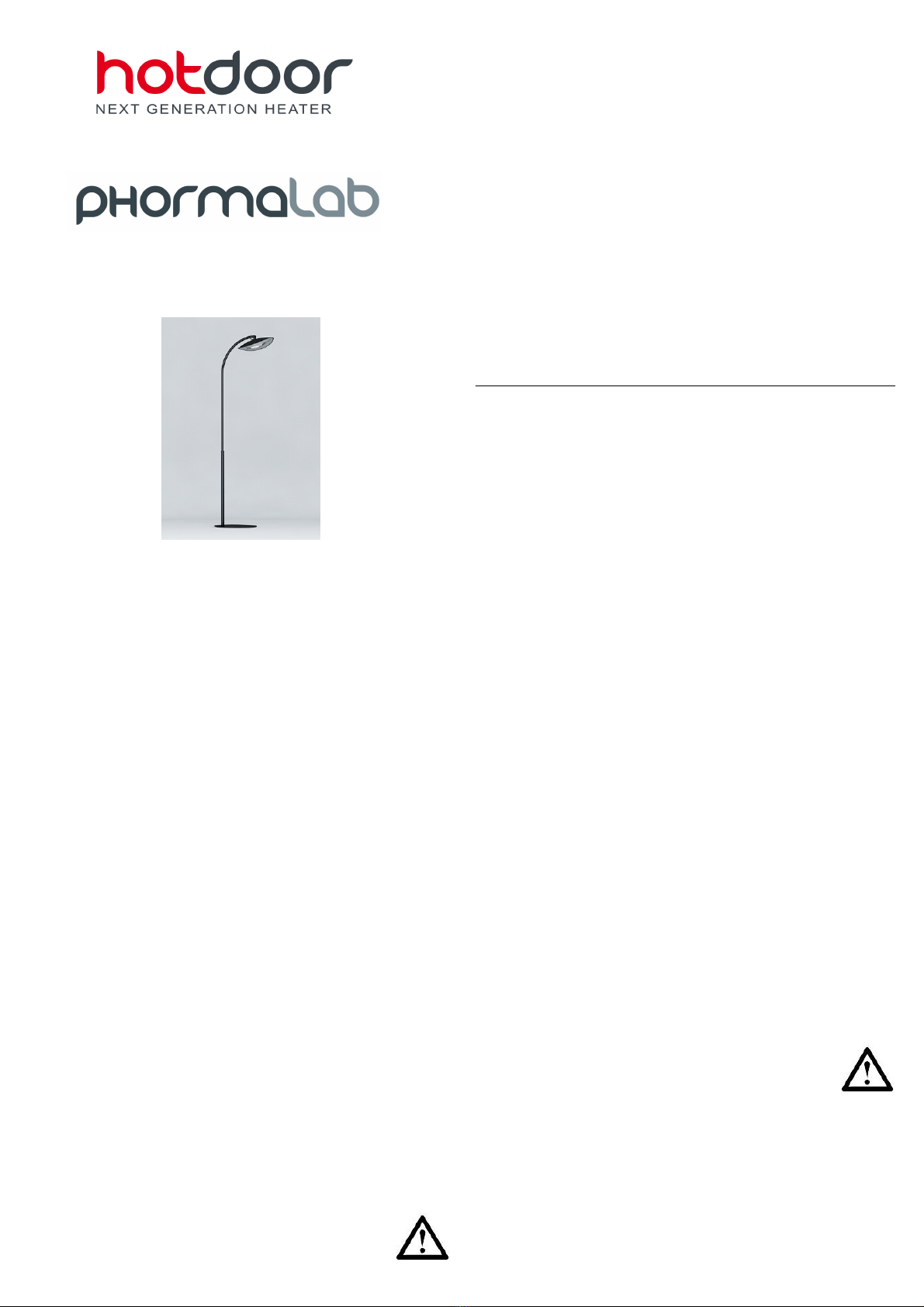
11. Rise the mounted pedestal vertically and adjust the heater’s orientation
to the desired direction and firmly tighten the skrew H.
12. Hotdoor heater is now mounted and ready for use. If you need a firm
position, anchor the basis to the floor putting an appropriate anchor plug in
the hole that is in the back sides of basis.
WARNING: in case of outdoor use, always apply proper waterproof
connections to electric cables (pic. A)
FR - INSTRUCTIONS DE MONTAGE
Montage de l’appareil de chauffage hotdoor avec
des attaques HCA01-02-03 (avec tige à sol)
Attention: L’appareil de chauffage hotdoor doit être monté et orienté
à distance de sécurité des murs, parois et des objets inflammables. Il
faut suivre les instructions contenues dans la notice d’utilisation et
entretien de l’appareil chauffante Hotdoor.
1. Pièces contenues dans l’emballage:
A. Appareil de chauffage hotdoor
B. Tube de soutien
C. Base pour la tige
D. Tube de base
E. Raccord pour câbles électriques
F. Trois vis M8
G. Une vis M4
H. Une vis M6 avec rondelle
2. Choisir l'orientation l'appareil chauffant: il peut être installé en position
longitudinale ou transversal, en desserrant les deux vis M6 qui fixent la
connexion supérieure de la lampe et en tournant la même connexion de
90°. Il faut soigner de ne pas tordre le câble d'alimentation et visser la
rotule tournante dans la nouvelle position avec les mêmes vis.
3. . Insérer l'extrémité libre du câble électrique de la lampe A, dans la fente
d'entrée du tube de support B et faire le glisser à l'intérieur, jusqu'à que à
dans la fente s’insère également la gaine en silicone qui sorte de la lampe
(une triple protection du câble d'alimentation.
4. Fixer la lampe A à l'extrémité du tube de support B, en serrant la vis H.
La vis doit être vissée avec la spéciale rondelle en dotation. À la fin du
montage la vis doit être serrées de sorte que la lampe ne puisse pas
accidentellement pivoter et donc surchauffer murs, éléments
potentiellement inflammables, ou prises de courant.
5. Le câble doit être complètement extrait de l'autre côté du tube.
6. En tenant les pièces sur une carton ou une surface anti-égratignure,
fixer le tube D à la base, en serrant avec force les trois vis longues F
fournies dans le paquet et en plaçant la fente du tube D, comme indiqué de
la figure, vers l'arrière de la base.
7. Insérer le câble d'alimentation provenant de la plante électrique, dans la
fente à la base du tube D , jusqu'à qu'il ressorte de l'autre côté au moins
20/30 cm.
Attention: de la plant électrique doit toujours arriver un
câble à double isolation (avec section de 3x1.5 mm2) type
HAR et avec 6-9 mm de diamètre, afin d'éviter tout risque
de mettre sous tension les parties métalliques de
l'attaque. Dans le cas où le câble en provenance de la
plante n'est pas à double isolation, il faut le changer avant le montage
de la lampe.
8. Approcher la base, avec le tube monté sur celle-ci (C + D), au tube de
lampe (B + A) et couper les câbles électriques d'une longueur suffisante
pour la connexion des câbles..
9. Connecter les deux câbles avec le raccord d’étanchéité, en suivant les
instructions contenues dans le paquet et soigner de coupler phase avec
phase, neutre avec neutre, et terre avec terre. Serrer les boulons de pour
assurer l'intégrité de l'étanchéité des câbles.
10. Faire glisser le raccord à l’intérieur du tube D (vers la base) pour
20/30cm. Enfin, insérer le tube B avec la lampe, dans le tube de base et le
fixer avec la vis G.
11. Positionner la tige en vertical et orienter la lampe dans la direction
choisie, et serrer définitivement la vis H.
12. La lampe hotdoor est maintenant assemblé et prêt à l'emploi. Dans le
cas où on souhaite fixer la lampe au sol avec des vis tamponnées, percer
la base C dans les positions appropriées et insérez les vis.
AVERTISSEMENT: en cas d'utilisation à l'extérieur, appliquez toujours
propres connexions étanches pour câbles électriques (fig. A)
DE - MONTAGEANWEISUNGEN
Montage des Heizstrahlers Hotdoor mit einzelnem
Ständer HCA01-02-03
Achtung: der Heizstrahler Hotdoor muss in einem Sicherheitsabstand
von Mauern, Wänden, oder entflammbaren Gegenständen montiert
oder gerichtet werden. Bitte folgen Sie aufmerksam die
Bedienungsanleitung des Heizstrahlers Hotdoor.
1. Lieferumfang:
A. Heizstrahler Hotdoor
B. Stützrohr
C. Fuβ
D. Fuβrohr
E. Verbindung für Stromkabel
F. Drei Schrauben M8
G. Eine Schraube M4
H. Eine Schraube M6 mit Scheibe
2. Wählen Sie die Stellung des Gerätes: das Gerät kann sowohl in
longitudinaler als auch in transversaler Stellung auf diese Weise installiert
werden: lösen Sie die zwei Schrauben M6, die die obere Kopplung an der
Lampe befestigen, und drehen Sie die selbe Kopplung von 90°, dabei
geben Sie acht, dass Sie das Stromkabel nicht biegen; danach befestigen
Sie die Kopplung in der neuen Stellung mit den selben Schrauben wieder.
3. Stecken Sie das freie Ende des Stromkabels, das aus der Lampe A
kommt, in den dafür vorgesehenen Schlitz des Stützrohrs B ein, und lassen
es hinein schieben, bis auch die Silikon Hülse, die aus der Lampe kommt,
in den Schlitz hineingeht (dreifacher Schutz des Stromkabels).
4. Befestigen Sie den Strahler A am Ende des Stützrohr B durch das
Anziehen der Schraube H. Die Schraube muss mit der belieferten
gerändelten Scheibe montiert werden. Am Ende der Montage soll die
Schraube gut angezogen werden, damit die Lampe nicht zufällig drehen
kann und die Wände, brennbare Gegenstände oder Steckdosen überhitzen
kann
5. Das Kabel muss aus der anderen Seite des Rohrs völlig herausgeholt
werden.
6. Legen Sie die Teile auf einen Karton oder auf einen Schütz gegen
Kratzer und befestigen Sie das Rohr D am Fuβdurch sehr festes Anziehen
der drei langen vorhandenen Schrauben F und stellen Sie den Schlitz des
Rohrs D nach der Kehrseite des Fuβes wie in der Abbildung.
7. Stecken Sie das Stromkabel, das von der Anlage kommt, in den Schlitz
am Ende des Rohrs D, und lassen Sie es 20/30 cm von der anderen Seite
herauskommen.
Achtung: von der elektrischen Anlage muss immer ein
HAR Kabel mit doppelter Isolierung (Schnitt 3x1.5 mm2),
Durchmesser 6-9 mm kommen, um jede Gefahr zu
vermeiden, die Metellteile der Kupplung in Spannung zu
stellen. Wenn das Kabel, das von der Hausanlage kommt, nicht mit
doppelter Isolierung ist, lassen Sie es anpassen, bevor Sie den
Strahler montieren.
8. Stellen Sie den Fuβmit dem montierten Rohr (C+D) näher an das Rohr
mit der Lampe (B+A) und schneiden Sie die Stromkabel zu einer
genügenden Länge für die Verbindung der Kabel.
9. Verbinden Sie die beiden Kabel mit dem dichten Verbindungsstück laut
den in der Verpackung enthaltenen Anweisungen und sorgen Sie dafür,
dass Sie Phase mit Phase, Neutralleiter mit Neutralleiter und Erdleiter mit
Erdleiter verbinden. Ziehen Sie die Mutter des Verbindungsstücks fest an,
so dass seine Dichtigkeit gewährleistet wird.
10. Schieben Sie das Verbindungsstück in das Rohr D (in die Richtung des
Fuβes) für 20/30 cm. Stecken Sie endlich das Rohr mit der Lampe in das
Rohr mit dem Fuβein und befestigen Sie es mit der Schraube G.
11. Bringen Sie den Ständer in eine senkrechtere Position und drehen Sie
die Lampe in die gewünschte Richtung, beim endlichen Anziehen der
Schraube H.
12. Der Heizstrahler ist jetzt montiert und gebrauchsfertig. Wenn Sie den
Strahler auf dem Boden mit Dübeln festmachen wollen, löchern Sie den
FuβC in den passenden Lagen durch und dann stecken Sie die Dübel ein.
ACHTUNG: Bei Anwendung im Auβenbereich , verwenden Sie immer
dichte Verbindungen mit angemessener Schutzklasse (Bild A)

Other Phormalab Heater manuals

Phormalab hotdoor HCA21-22-23 User manual

Phormalab

Phormalab hotdoor HCA21-22-23 User manual

Phormalab hotdoor HCA01 User manual

Phormalab

Phormalab hotdoor HCA01 User manual

Phormalab hotdoor HCA01 User manual

Phormalab

Phormalab hotdoor HCA01 User manual

Phormalab Hotdoor HCB01 User manual

Phormalab

Phormalab Hotdoor HCB01 User manual

Phormalab hotdoor User manual

Phormalab

Phormalab hotdoor User manual

Phormalab Hotdoor HAA01 User manual

Phormalab

Phormalab Hotdoor HAA01 User manual

Popular Heater manuals by other brands

VTS  Euroheat FiGHTER 100EH user manual

VTS Euroheat

VTS Euroheat FiGHTER 100EH user manual

Adler Europe AD 7728 user manual

Adler Europe

Adler Europe AD 7728 user manual

Harvia PO12-U1 Owner's/operator's manual

Harvia

Harvia PO12-U1 Owner's/operator's manual

Clatronic HL 3631 instruction manual

Clatronic

Clatronic HL 3631 instruction manual

Cadet Apex72 HW162 owner's guide

Cadet

Cadet Apex72 HW162 owner's guide

Termozeta TZR06N instruction manual

Termozeta

Termozeta TZR06N instruction manual

Sealey CD2013.V2 instructions

Sealey

Sealey CD2013.V2 instructions

Stelpro CWS1000930W user guide

Stelpro

Stelpro CWS1000930W user guide

EUROM B-4 1800 instruction manual

EUROM

EUROM B-4 1800 instruction manual

Polaris PCWH 2067 Di Manual instruction

Polaris

Polaris PCWH 2067 Di Manual instruction

Pelsue 1557 product manual

Pelsue

Pelsue 1557 product manual

HeatStar HS 3500DF Operating instructions and owner's manual

HeatStar

HeatStar HS 3500DF Operating instructions and owner's manual

EUROM Fanheater 600 instruction manual

EUROM

EUROM Fanheater 600 instruction manual

emerio FH-120669 instruction manual

emerio

emerio FH-120669 instruction manual

DeLonghi HTF 3031 Instructions for use & warranty

DeLonghi

DeLonghi HTF 3031 Instructions for use & warranty

Westfalia NSB-150C5 instruction manual

Westfalia

Westfalia NSB-150C5 instruction manual

Outwell Katla Series instruction manual

Outwell

Outwell Katla Series instruction manual

ARDESTO IH-2500-Q1S instruction manual

ARDESTO

ARDESTO IH-2500-Q1S instruction manual

manuals.online logo
manuals.online logoBrands
  • About & Mission
  • Contact us
  • Privacy Policy
  • Terms and Conditions

Copyright 2025 Manuals.Online. All Rights Reserved.