Photonic Universe MT50 User manual

REMOTE METER
Model: MT50
INSTRUCTION MANUAL
For use with solar charge controllers PU series, LS series, VS series,
Tracer MPPT series and other compatible controllers


Remote Meter
MT50
Please note that this remote meter (Model MT50) should only
be used with solar charge controllers PUxxxxB(P), LSxxxxB(P),
VSxxxxBN, Tracer TRxxxxBN(P) and other solar charge
controller models released in the future if the user manual
states that they are compatible with this MT50 remote meter.

Contents
1 Important SafetyInstructions .................................................................1
2 General Information...............................................................................2
2.1 Features......................................................................................2
2.2 Mainfunctions.............................................................................3
2.3 Recommendations......................................................................3
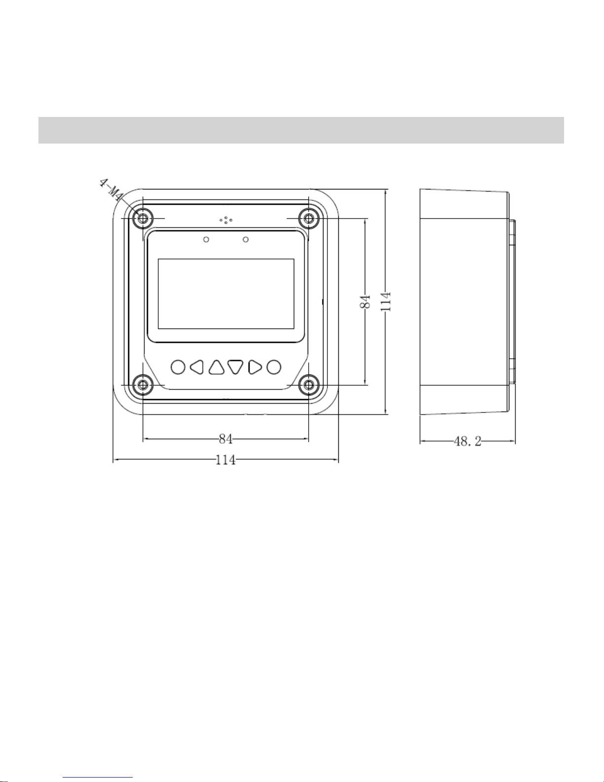
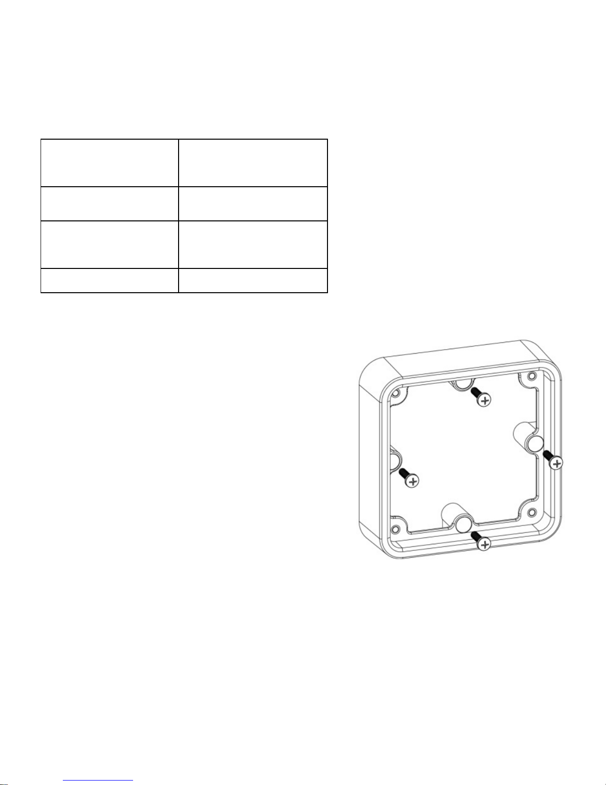
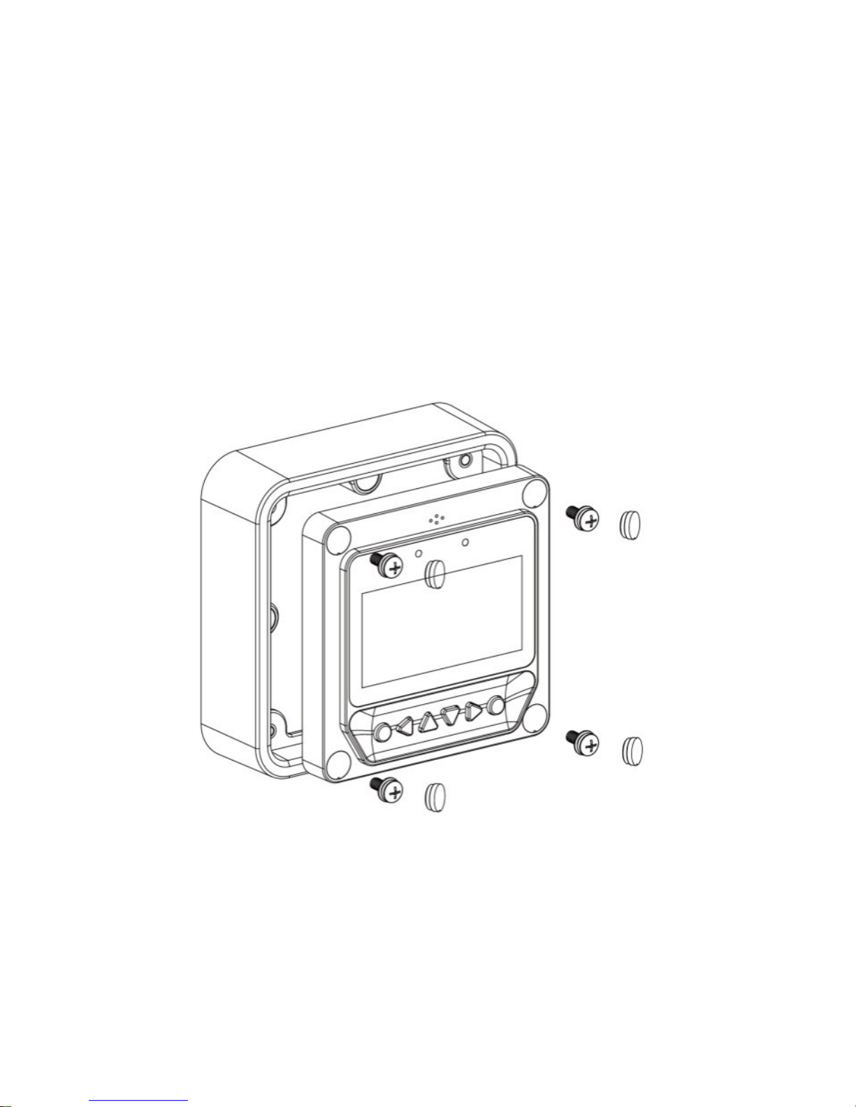
3Installation .............................................................................................4
4 Product Features...................................................................................8
5 Operation ............................................................................................12
5.1 Buttons......................................................................................12
5.2 Main menu ................................................................................13
5.3 Real-timemonitoring.................................................................14
5.4 Deviceinformation ....................................................................16
5.5 Test operation............................................................................16
5.6 Control parameters ...................................................................17
5.7 Loadsetting...............................................................................21
5.8 Device parameters....................................................................24
5.9 Devicepassword.......................................................................25
5.10 Factory reset............................................................................25
5.11 Failureinformation ...................................................................26
5.12 Meter parameters ....................................................................27
6 Technical Specifications......................................................................28

1
1 Important Safety Instructions
SAVE THESE INSTRUCTIONS:
This manual contains important safety, installation and operating
instructions for the remote meter.
General safety information
■Please inspect the MT50 thoroughly after it is delivered. If any damage is
seen, please notify the shipping company or our company immediately. A
photo of the damage may be helpful.
■Read all instructions and cautions in the manual before starting the
installation.
■Keep the MT50 away from rain, dust, vibrations, corrosive gas and intense
electromagnetic interference.
■Do not allow water to enter the remote meter.
■There are no user serviceable parts inside the remote meter. Do not
disassemble or attempt to repair it.

2
2 General Information
2.1 Features
The new-generation remote display unit MT50 for PUxxxxB(P), LSxxxxB(P),
VSxxxxBN and TracerxxxxBN(P) controllers is an associated display device
which supports both the latest communication protocol and the voltage
standard of
solar charge controllers. The product has many useful functions:
■Automatic identification of the type, model and relevant parameter data of
various solar charge controllers
■Real-time display of the operational data and working status of the
connection devices in digital, graphical and textual forms by a large-screen
multifunctional LCD;
■Direct, convenient and rapid operation of six navigation function keys;
■Both data and power flowing on the same lead, no need for external power;
■Real-time data monitoring and remote load switchover of the controllers,
data browse and modification of device parameters, charge control
parameters and load control parameters;
■Real-time display and acoustic alarm of failure information of the
connected devices;
■Longer communication distance via RS485.

3
2.2 Main functions
The main functions of the remote meter are the real-time monitoring of the
operational data and working status of the connected solar charge controller,
browsing and modification of charge/discharge control parameters, setting of
device parameters and load control parameters, the restoration of factory
defaults, based on LCD display and functional keys operation.
2.3 Recommendations
■Please note that MT50 can only be used with PUxxxxB(P), LSxxxxB(P),
VSxxxxBN and TracerxxxxBN(P) controllers. Confirm that you have a
compatible controller before purchase and use of the remote meter.
■Please do not install MT50 in a location with strong electromagnetic
interference or risk of contact with water.

4
3 Installation
Frame mount dimensions (
mm)

5
Mechanical
parameter Parameter
Overall dimension 114 x 114 x 32.7 mm
Mounting
dimension 88.6 x 88.6 mm
Terminal Φ4.3
Wall installation steps:
Step 1: Locate and drill screw holes
based on the frame mounting
dimensions of the base, and erect the
plastic expansion bolts;
Step 2: Use four ST4.2×32 self-tapping
screws to fix the frame;
Frame mounting

6
Step 3: Use four M4×8 pan head screws to mount MT50 surface onto
the frame;
Step 4: Mount the four associated screw plugs into the screw holes.
Frame mounting

7
Steps of surface mounting:
Step 1: Locate and drill screw holes based on the installation size of the
remote meter;
Step 2: Use four M4×8 cross recessed pan head screws with M4 nuts to
mount MT50 Surface onto the panel (or suitable self-tapping screws);
Step 3: Mount the four associated screw plugs into the screw holes.
Surface mounting
Note: Take full consideration of the plugging/unplugging space of the
communication cable and the length of the cable during installation to
see if they are appropriate.

8
4 Product Features

9
RS485 communication and power interface
Rear View
Failure indicator
Failure indicator flashes in case of failure of the connected device. For failure
information please check the solar charge controller manual.

10
Alarm
Fault audible alarm, could be activated or deactivated.
Communicationindicator
Indicate communication status when MT50 is connected to the controller.
Display screen
User monitoring and operation interface.
Buttons
The meter buttons include four navigation buttons and two operational
buttons. See specific instructions in the Operations section.
RJ45 communication and power interface
Communication and power supply socket used for connection to a solar
charge controller.
Note: Please use the communication plug which is marked with “MT”
to connect MT50
Monitoring screen

11
Day and night icons
- Night,- Day: The threshold voltage is 1V. Higher than 1V is daytime.
Charge current icon
The icon moves if there is charge current.
Battery icon
The estimated battery capacity is shown.
Note: When the battery is over discharged, the icon displayed is “ ”.
Battery status icons
- Normal voltage, - Under voltage, - Over discharge.
Load current icon
The icon moves if there is discharge current.
Load status icon
- Load On, - Load Off.
Note: In Manual Mode, pressing the "OK" button will switch the load
status between "ON" and "OFF"

12
5 Operation
5.1 Buttons
The buttons are respectively (from left to right) “ESC”, “Left”, “Up”, “Down”,
“Right” and “OK” . Use of these navigation buttons can be shown in the
schematic operation diagram below:
Schematic operation diagram

13
The default entry page is the browse mode. Press the button and input the
correct password to enter the modification mode. Use and buttons to
move the cursor, while and buttons can be used to modify the
parameter values when the cursor has selected the parameter; and
buttons can then be used to respectively confirm or cancel the modification of
the parameter.
5.2 Main menu
Enter the Main Menu by pressing . and buttons are used to move
the cursor to select the menu items; and buttons are respectively
used to enter or exit the corresponding sections of the menu.
1. Monitoring
2. Device Info.
3. Test Operation
4. Control Para.
5. Load Set
6. Device Para
7. Device PSW.
8. Factory Reset
9. Failure Info.
10. Meter Para.

14
5.3 Real-time monitoring
There are 14 pages under real-time monitoring. Please note as below:

15
Operational tips: Move between rows by pressing or buttons. Move
along a row by pressing or buttons.

16
5.4 Device information
The product model, parameters and SN code of the controllers are displayed
below:
Operational tips: and buttons are respectively used to turn the
browse page upward and downward.
5.5 Test operation
Load switch test operation can be conducted on the connected solar
charge controller to see if the load output is normal. The test operation
does not affect the working settings under the actual load, which means
that the solar controller will exit from the test mode when exiting the
operational interface of the test.
Operational tips: enter the page and input the correct password; use
and buttons to modify the On/Off status values; use and buttons
respectively to confirm or cancel the test operation.
Table of contents
Other Photonic Universe Measuring Instrument manuals