- 3 -
Getting Started
We have created this Service & Repair Guide to assist you with the servicing of your PhotoVu.
This guide is designed to help you disassemble the PhotoVu for repair. Once the internal parts
are accessible, advanced computer troubleshooting skills will be required to diagnose and
repair the issue.
All PhotoVu models are covered with the exception of the PV1900, PV1040, PV1045, and
PV1540.These models are not repairable.
Additional help and technical information can be found at www.photovu.com/support and
www.photovu.com/help.
Determine Your Generation of PhotoVu Model
There are three major generations of PhotoVu digital picture frames. In some cases, a model
number might overlap several generations as in the PV2265.
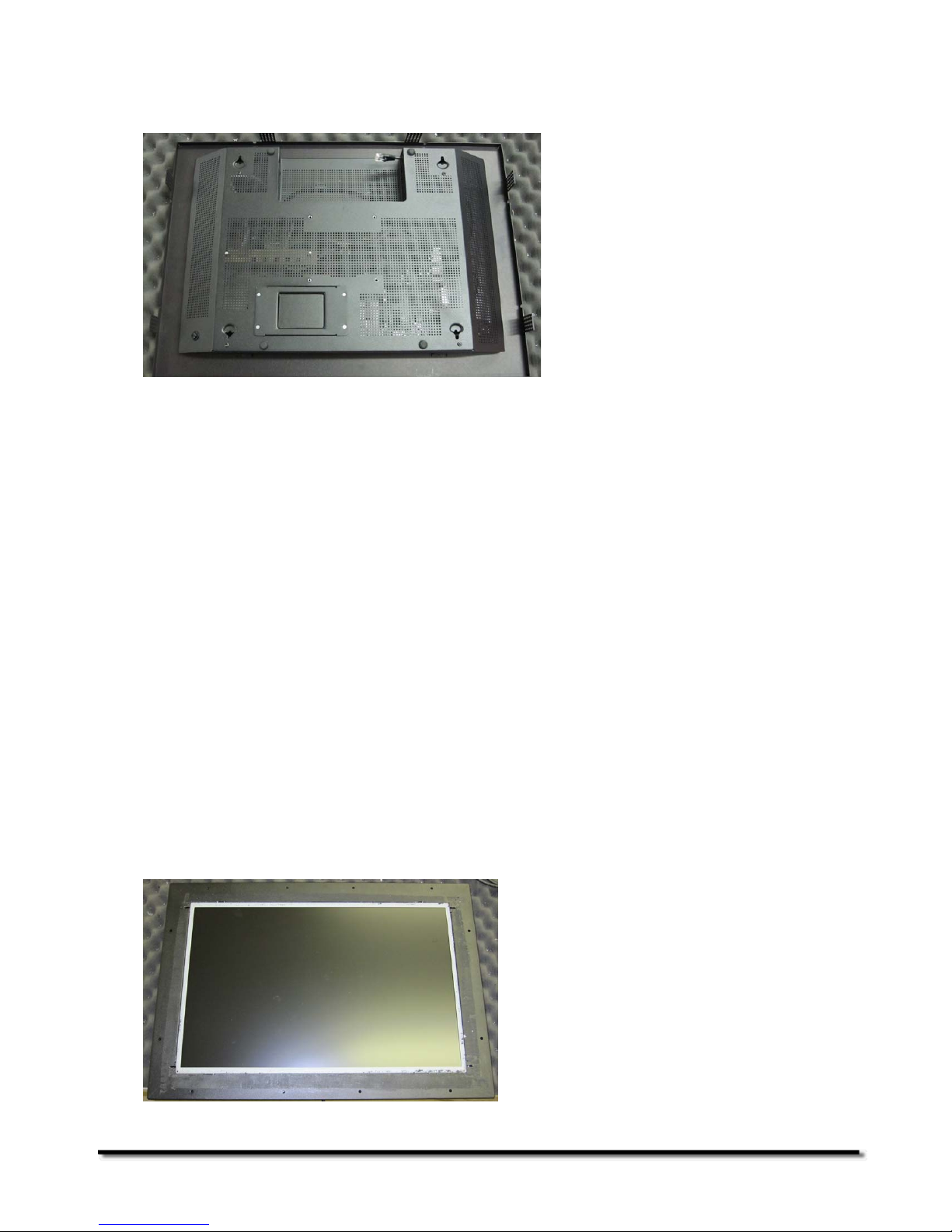
Generation One (G1)
PhotoVu models in this generation include the 1740, 1740s, 1750, 1910, 1940, 1940s,
1940dc, 1940sdc, 1945, 1950, 1960, 1965, and 1965w. G1 units have two major enclosure
parts: a body housing the electronics and a two-part bracket that holds the LCD panel.
Generation Two (G2)
PhotoVu models in this generation include the 1965, 1965w, and 2265w. G2 units have a
single enclosure that holds all the electronics and LCD panel.
Generation Three (G3)
PhotoVu models in this generation include the 2265w, 2265wds, 2270w, 2270wds, 2275w,
and 2275wds.G3 units have an internal mounting plate for the electronics and LCD panel, a
rear enclosure cover, and a faceplate that holds the matboard and picture frame.
In the steps below, you will confirm your PhotoVu generation once you remove the picture
frame and matboard.
Removing the Picture Frame
This step requires use of a #1 Phillips head screwdriver.
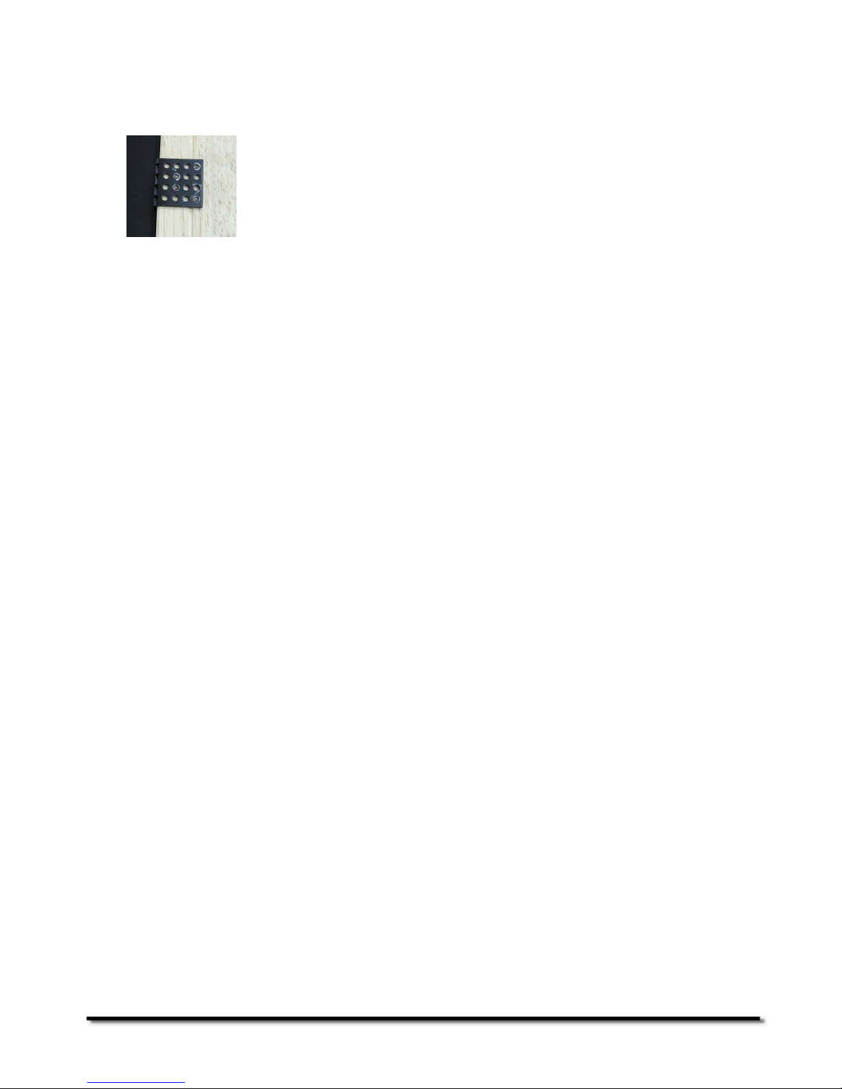
G1/G2 Units
G1 and G2 units have picture frame mounting brackets. One side of the bracket screws into
the picture frame and the other side into the PhotoVu’s rear body enclosure. Remove all
screws and brackets from your PhotoVu.