Photronic Mini Pan/Tilt Dome Camera User manual

INSTRUCTION MANUAL Ver 1.1.0
Mini Pan/Tilt Dome Camera
Firmware Ver. 1.1

M
ini Pan/Tilt Dome Camera Instruction Manual 2/21
○
1Introduction
Features 3
Product&Accessory 4
○
2Installation
CheckingHomePosition 5
DirectCeilingMountwithMountingPlate 6
WallMountwithWallMountBracket 7
HowtoSettheDIPSwitches 9
Connection 12
○
3Operation
CheckingbeforeOperation 13
Start OSD Menu
14
Preset
14
Group
14
OSD Display of Main Screen
15
○
4OSD Menu
General Rules of Key Operation for Menu
16
Main Menu
16
Display Setup
16
Preset Setup
17
Group Setup
18
Alarm Setup
19
○
5Specification
20
CONTENTS

M
ini Pan/Tilt Dome Camera Instruction Manual 3/21
Features
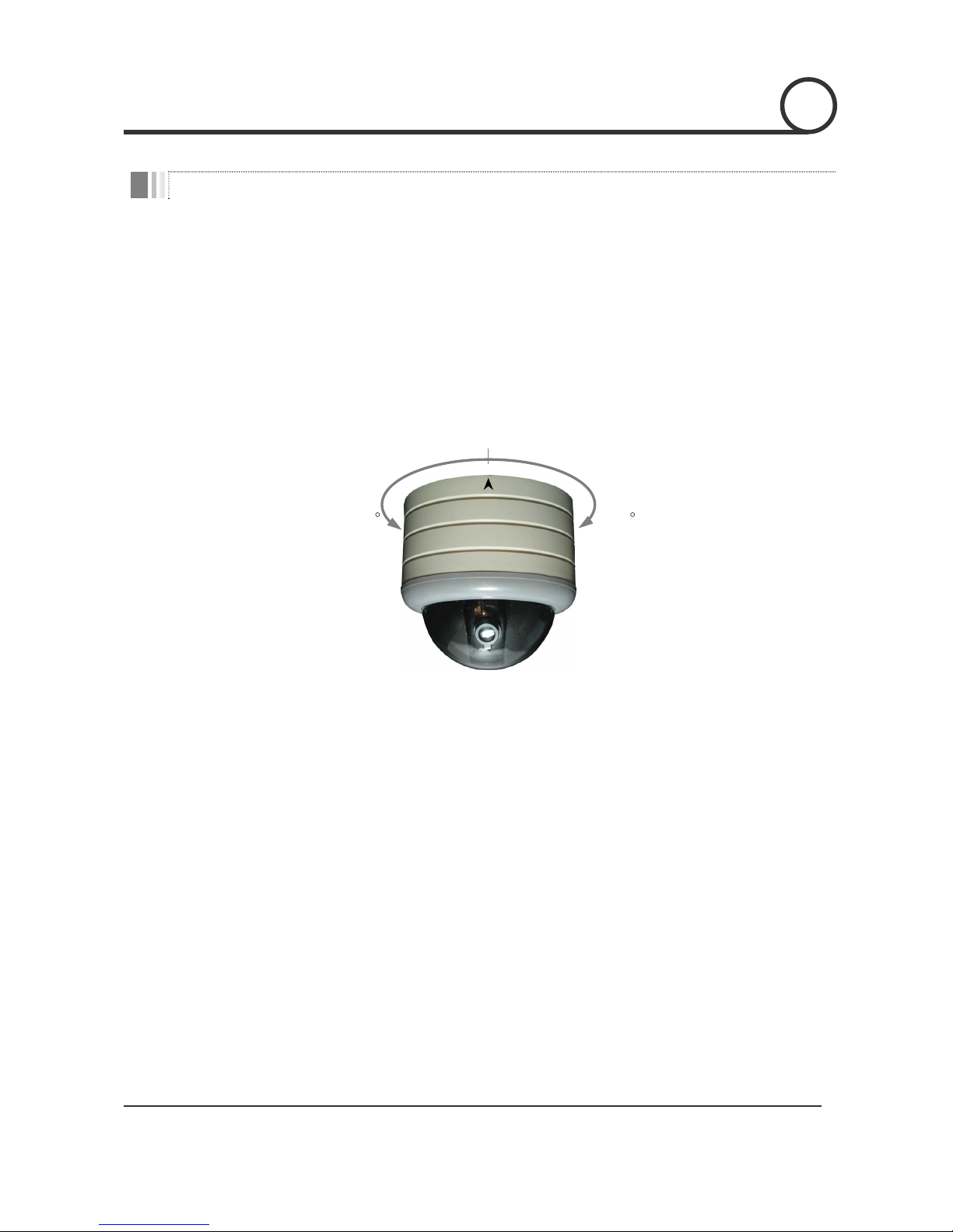
Powerful Pan/Tilt Function
zHigh Speed Pan/Tilt Operation : MAX. 50°/sec
zVector Drive : Simultaneous Pan/Tilt Calculation & Positioning
zHigh Precision Operation : 0.5°/sec
Preset & Group Function
z32 Presets with Independent Dwell Time & Digital In/Out
z4 Groups : 20 Presets / 1 Group
OSD(On Screen Display) Menu
zVarious Functions with OSD Menu
zOSD with Camera ID, Pan/Tilt Angle, Alarm In/Out, Preset Information
Alarm I/O Function
zIf optional Alarm I/O module is connected to Mini P/T dome camera, maximum 8 external sensor
inputs and 4 relay outputs can be utilized to give more intelligence to this camera.
zIf an external sensor is activated, camera can be set to move to corresponding preset position. Also,
the output relay can be matched to some specific preset positions to do counteractions such as
turning on the light or sounding the alarm.
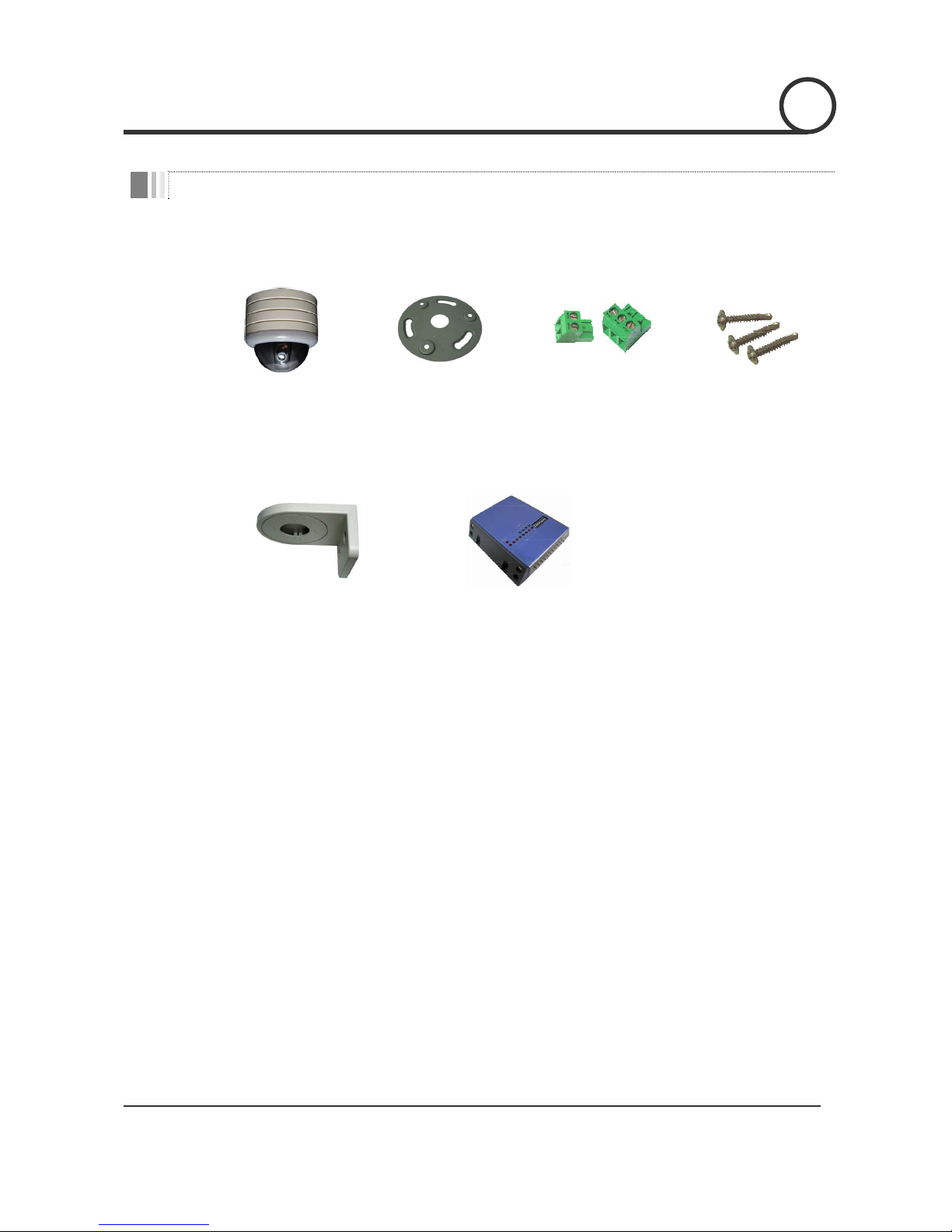
Compact size and Easy installation
zThe size of the dome is as small as ∅104 ×110(H) mm.
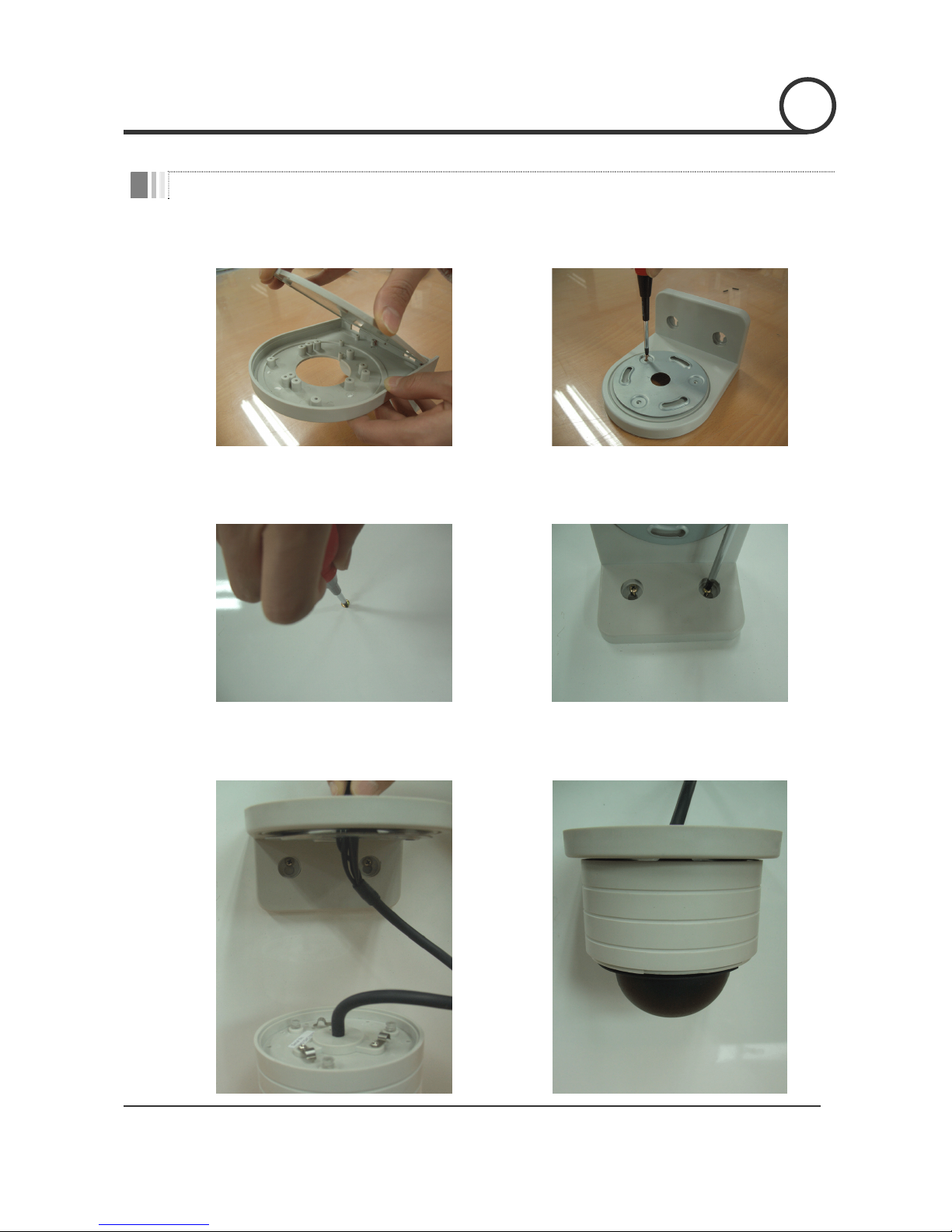
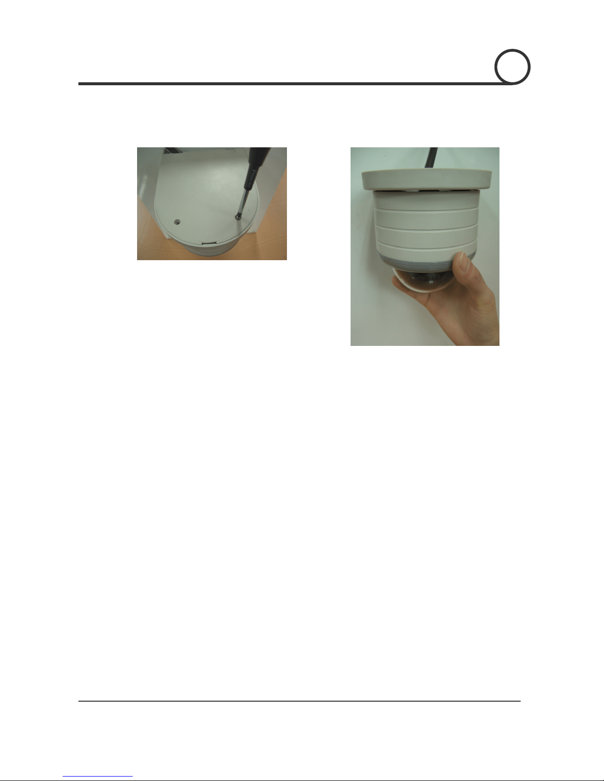
zThere are two mounting choices.
Direct ceiling mount with mounting plate.
Wall mount with wall mount bracket.
INTRODUCTION 1

M
ini Pan/Tilt Dome Camera Instruction Manual 4/21
Product & Accessories
zDome Camera zMount Plate zTerminal Blocks zScrews
Options
zWall mount bracket zAlarm I/O module
INTRODUCTION 1

M
ini Pan/Tilt Dome Camera Instruction Manual 5/21
Checking Home Position
zThe angular range of pan motion is limited to 345°(±172.5°). Therefore, please, check the home position of
camera which is marked with an arrow mark as shown in the picture below.
zWhenever, camera is turned on, camera is located this home position automatically. To facilitate easy
accessing to major target view, it is highly recommended to mount camera to face this arrow toward the
target view. Also, camera always regard this home position as zero angle and move pan motion from -
172.5°to +172.5°.
172.5172.5
Home Position
INSTALLATION 2

M
ini Pan/Tilt Dome Camera Instruction Manual 6/21
Direct ceiling mount with mounting plate
○
1For cabling, make a hole sized 30~40mm on the
ceiling panel.
○
2Attach the mounting plate with screws included.
○
3Insert the camera cable into the hole in the
mounting plate.
○
4Locate three transparent bosses of camera to the
three slots of the mounting plate
○
5By pushing and twisting the camera into the
mounting plate, fix the camera to the mounting
plate.
○
6By pushing and twisting the gray ring, assemble
the clear dome cover. Care must be taken not to
make fingerprint on to the clear dome.
INSTALLATION 2

M
ini Pan/Tilt Dome Camera Instruction Manual 7/21
Wall mount with wall mount bracket.
○
1Remove the top cover of wall mount bracket. ○
2Assemble the mount plate on to the wall mount
bracket with screws included.
○
3Mark appropriate two screw hole points. Tighten
the screw loosely to hang the bracket in the next
step.
○
4After hang the bracket on the screw in step ○
3,
pull down the bracket for screws to slide into
slots. Then, tighten screw completely.
○
5Make cable to pass through the center hole of
bracket.
○
6By pushing and twisting the camera into the
mounting plate, fix the camera to the wall
mount.
INSTALLATION 2

M
ini Pan/Tilt Dome Camera Instruction Manual 8/21
○
7Assemble the top cover of wall mount bracket with
screws included.
○
8By pushing and twisting the gray ring, assemble
the clear dome cover. Care must be taken not to
make fingerprint on to the clear dome.
INSTALLATION 2

M
ini Pan/Tilt Dome Camera Instruction Manual 9/21
How to set the DIP switches
○
1By pressing the side lock of shield dome (black
inner cover), take off the shield dome.
○
2Adjust the DIP switch on the PCB to configure
your camera. Refer to the switch settings bellow.
Camera ID Selection
12345678
ON
Address
P1
TR
P0
zBy changing the DIP switch, you can set the binary number for camera
ID. ON state of switch means ‘1’ and OFF means ‘0’.
Ex) If you want to set camera ID as 10.
12345678
ON
1 (if 'ON')
16 (if 'ON')
8 (if 'ON')
4 (if 'ON')
2 (if 'ON')
ID : 0+2+0+8+0=10
zYou can assign camera ID in the rage 1~31. Do not use ID ‘0’
zFactory default of Camera ID is ‘1’.
zWhen you want to operate the camera with a controller. The Camera ID
in this DIP switch setting must be identical to the camera ID of the
controller. If you have multiple cameras, it is recommended to
memorize the Camera IDs and their camera locations.
INSTALLATION 2

M
ini Pan/Tilt Dome Camera Instruction Manual 10/21
Control Protocol Selection
12345678
ON
Address
P1
TR
P0
zSelect the appropriate Protocol with DIP switch combination.
Switch State
P0(Pin 6) P1(Pin 7)
Protocol / Baud Rate
OFF OFF PELCO-D, 2400 bps
ON OFF PELCO-D, 9600 bps
OFF ON PELCO-P, 4800 bps
ON ON PELCO-P, 9600 bps
zIf you want to control using DVR or P/T controller, their protocol must
be identical to that of your camera. Otherwise, the camera will be
out of control.
zIf you changed camera protocol by changing DIP S/W, the change
will be effective after you reboot the camera.
INSTALLATION 2

M
ini Pan/Tilt Dome Camera Instruction Manual 11/21
Terminal Resistor Setting
12345678
ON
Address
P1
TR
P0
T
erminal resistor is used if your system is one of following two cases.
zCase1: Control cable between camera and controller is
relatively very long (1:1 connection)
If communication cable is very long, the electrical signal will bound
in both terminal points. This reflected signal cause distortion of
original signal. Accordingly, the camera can be out of control. In this
case, the terminal resistor of both sides i.e. camera and controller
must be set to ‘ON’ state to absorb those unwanted reflections.
zCase2: Multiple cameras are controlled at the same time.
Due to similar reasons with case 1, the terminal resistors of
controller and the last camera must be set to ‘ON’ state. The last
camera may be decided by longest cable length. Do not turn on the
terminal resistor of all cameras.
Controller
#1 #2 #n
Terminal Resisto
r
ON
Terminal Resistor ON
Terminal Resistor
OFF
Terminal Resistor
OFF
R
S-485
INSTALLATION 2

M
ini Pan/Tilt Dome Camera Instruction Manual 12/21
Connection
12V DC
RS-485
BNCBNC
Power
Monitor
Controller
Alarm I/O Module
Power Connector
zPlease, check carefully the voltage and current capacity of the electrical power source. The rated
electrical power to operate this camera is as follows.
With External Alarm I/O module: DC 12V / 1A
Without External Alarm I/O module: DC 12V / 500mA
zAfter assemble power adaptor wires to 3 pin terminal block included, plug into power connector. It is
noted that the center pin is no connection.
zCare must be taken with polarity of power. The polarity sign is molded on the connector. If reverse
polarity is applied, the camera will be damaged seriously.
Video Out Connector
zConnect with BNC coaxial cable.
RS-485 Communication connector
zAfter assemble communication wires to 2 pin terminal block included, plug into communication
connector. The D+, D- lines should be connected ‘+’,‘-‘ pins respectively.
Alarm I/O
zUse this connecter if you have Alarm I/O module. If you need detail information, please refer User’s
manual of Alarm I/O module.
INSTALLATION 2

M
ini Pan/Tilt Dome Camera Instruction Manual 13/21
Checking Before Operation
zBefore power is applied, please, check the cable very carefully.
zThe camera ID of the controller must be identical to that of the target camera. The camera ID can be checked
by reading DIP switches in the camera.
zIf your controller supports multi-protocols, the protocol must be changed to match to that of the camera.
zIf you have changed the camera protocol by changing DIP Switch, the change will be effective after you
reboot the camera.
zSince the operation method can be different for each controller available, refer to the manual for your
controller if camera can not be controlled properly. Major operations of this manual are based on the
standard Pelco® Controller.
OPERATION 3

M
ini Pan/Tilt Dome Camera Instruction Manual 14/21
START OSD MENU
zFunction Using the OSD menu, Preset, Group and Alarm I/O function can be configured for each
application.
zStart Menu After type the numeric key 95, press the Preset key to start OSD menu.
[95] + [Preset]
PRESET
zFunction Max. 32 positions can be stored as Preset position. Using Preset key together with Numeric
keys in the controller, Preset can be stored or executed. Also, dwell time and alarm out
relay settings for each preset can be configured using the OSD menu.
zSet Preset After you type 1 ~ 32 numeric key, press Preset key for longer than 2 seconds. Without OSD
menu, this can be done using Controller anytime.
[1 ~ 32] + [Preset] (press longer than 2 seconds)
zRun Preset After you type 1 ~ 32 numeric key, press Preset key shortly. Without OSD menu, this can be
done using Controller anytime.
[1 ~ 32] + [Preset] (press shortly)
zDelete Preset Use OSD menu.
GROUP
zFunction The Group function enables to execute sequential motion composed of several Presets. Max
4 Groups can be stored. Each Group can have max 20 Preset entities. By using menu, the
Group can be created, modified and deleted. Dwell time is defined for each preset position
Preset 1 Preset 5 Preset 3
Max 20 Entities
Dwell Time
zSet Group Use OSD Menu.
zRun Group <Using controller with Pattern key> After you type 20+Group No. (i.e. 21~24), press
Pattern key in the controller.
[21~24] + [Pattern] Ex)Ifgroupnumberis3,press23+Pattern
<Using controller without Pattern key> After type 80+Group No. (i.e. 81~84), press Preset
key in the controller.
[81~84] + [Preset] Ex)Ifgroupnumberis3,press83+Preset
zDelete Group Use OSD Menu.
OPERATION 3

M
ini Pan/Tilt Dome Camera Instruction Manual 15/21
OSD Display of Main Screen
PRESET 1
O:1---
28/-42 CAM 1 I:-2--5---
P/T Information Camera ID Alarm Information
Action Title
zP/T Information Shows current Pan/Tilt angle in degree.
zCamera ID Shows current Camera ID
zAction Title Shows current preset number when a preset is set or run. If Preset is not defined, the
title will be shown as "UNDEFINED".
zAlarm Information Shows current state of Alarm I/O module. If an I/O point is ON state it will show a
number corresponding to each point no. If the I/O is OFF state, '-' will be displayed.
Ex) Point 1st and 7th of Alarm inputs are ON state and 2nd and 4th of output are ON. OSD
will be show as below.
O:-2-4
I:1-----7-
OPERATION 3

M
ini Pan/Tilt Dome Camera Instruction Manual 16/21
General Rules of Key Operation for Menu
zThe menu items surrounded with ( ) mean they have their sub menu.
zFor all menu level, to go down into sub menu, press NEAR key and to go up to upper menu, press FAR key.
If you learn by heart the rules that NEAR key is similar to Enter key in computer and that FAR key is always
Esc key in computer, the following explanations will be easy to understand.
zTo move cursor from item to item in the menu, tilt the joystick for all directions (Up/Down or Left/Right) as
you like.
zIf you want to confirm a menu item, press NEAR key.
zTo change a value of an item, tilt your joystick Up or Down directions.
zIf you want to confirm a value you changed, press NEAR key to save it or press FAR key to cancel it.
zIf you don’t operate menu for longer than 5 min, the menu will be disappeared automatically.
Main Menu
MINI P/T DOME CAMERA
------------------------------
(DISPLAY SETUP)
(PRESET SETUP)
(GROUP SETUP)
(ALARM SETUP)
------------------------------
DISPLAY SET UP
DISPLAY SETUP
------------------------------
CAMERA ID ON
ACTION TITLE ON
P/T INFORMATION ON
ALARM INFORMATION ON
DISPLAY FACTORY RESET
------------------------------
zDisplay Setup Enable/Disable of OSD display on Main Screen.
zPreset Setup Preset configurations such as Preset position, Dwell
time, Alarm I/O state for each 32 presets.
zGroup Setup Define entry and order of preset in each group.
zAlarm Setup Define Alarm actions if Alarm Input is activated.
Current version allows “Move to Preset”action.
This menu defines Enable/Disable of OSD display on Main Screen. If
P/T Information is set to be AUTO, the P/T angle is displayed only when
P/T angle is changed.
zCamera ID [ON/OFF]
zAction Title [ON/OFF]
zP/T Information [ON/AUTO/OFF]
zAlarm Info. [ON/OFF]
If you activate Display Factory Reset, all options will return to ON state.
OSD MEMU 4

M
ini Pan/Tilt Dome Camera Instruction Manual 17/21
PRESET SETUP
PRESET SETUP
------------------------------
PRESET NUMBER : 1
DWELL TIME : 3
RELAY OUT : -2-4
(EDIT PRESET SCENE)
(CLEAR PRESET)
------------------------------
Edit Preset Scene
EDIT PRESET SCENE 1
------------------------------
USE THE JOYSTICK OR KEYBOARD
TO POSITION THE CAMERA
PRESS FOCUS NEAR TO SAVE
PRESS FOCUS FAR TO CANCEL
0/-42
Setup Relay Output
RELAY OUT : -2-4
RELAY OUT : -2-4
Near Key
RELAY OUT : -2-4
Left/Right
Up/Down
RELAY OUT : 12-4
Up/Down
RELAY OUT : ---4
N
ear/Far
① From Relay Out tab, you can select first digit (Relay 1) value by pressing Near key.
② By tilting joystick Up/Down, the value can be toggled the '-' sign or a number representing its digit.
③ Also, by tilting joystick Left/Right, you can move to next digit.
④ After you have changed values, press Near key to save it or press FAR key to cancel it.
zPreset Number [1~32]
zDwell Time [0~255] Seconds
The dwell time is effective whenever group action
is running. This time interval means how long the
motion is paused after P/T arrives that Preset
position.
zRelay Out [Relay1 - Relay2 - Relay3 - Relay4]
If you set a relay to ON state, the corresponding
number will be displayed. If a relay is set to OFF
state, '-' will be displayed. For example, in the left
figure, relay 2 and 4 are set to ON state.
(EDIT PRESET SCENE) menu is selected. The camera will move to the
position corresponding to the current Preset selected.
○
1Move camera to a position desired by tilting joystick.
○
2By pressing Near key, store current Preset.
○
3To cancel current change, use Far key.
OSD MEMU 4

M
ini Pan/Tilt Dome Camera Instruction Manual 18/21
GROUP SETUP
GROUP SETUP
------------------------------
GROUP NUMBER : 1
P1 P2 P32 x0 x0
x0 x0 x0 x0 x0
x0 x0 x0 x0 x0
x0 x0 x0 x0 x0
CLEAR
------------------------------
Setup Group
GROUP NUMBER : 1
P1 P3 P32 x0 x0
x0 x0 x0 x0 x0
x0 x0 x0 x0 x0
x0 x0 x0 x0 x0
GROUP NUMBER : 1
P1 P3 P32 x0 x0
x0 x0 x0 x0 x0
x0 x0 x0 x0 x0
x0 x0 x0 x0 x0
Near Key
GROUP NUMBER : 1
P1 P3 P32 x0 x0
x0 x0 x0 x0 x0
x0 x0 x0 x0 x0
x0 x0 x0 x0 x0
Left/Right
Up/Down
Near Key
GROUP NUMBER : 1
P1 P3 P32 x0 x0
x0 x0 x0 x0 x0
x0 x0 x0 x0 x0
x0 x0 x0 x0 x0
Up/Down
GROUP NUMBER : 1
P2 P3 P32 x0 x0
x0 x0 x0 x0 x0
x0 x0 x0 x0 x0
x0 x0 x0 x0 x0
Near/Far
Near/Far
zGroup Number [1~4]
zAction [x0, P1~P32]
The sign x0 means no action. If you assign P1, P2
and P32 as entities, the P/T camera will move those
presets repeatedly after Group function is
executed.
zClear Clear all 20 entities to x0.
② After changing the value desired using joystick, press the Near
key to save. If you press the Far key corresponding changes will
be canceled.
③ Scroll Group Number using Up/Down motion of joystick. Press the
Near key when you find a group number you want to edit.
① After moving cursor to appropriate
entity to be edited using Up/Down
motion of joystick, press the Near key
to change.
OSD MEMU 4

M
ini Pan/Tilt Dome Camera Instruction Manual 19/21
ALARM SETUP
ALARM SETUP
------------------------------
ALARM1 ACTION : PRESET 1
ALARM2 ACTION : PRESET 2
ALARM3 ACTION : NOT USED
ALARM4 ACTION : NOT USED
ALARM5 ACTION : NOT USED
ALARM6 ACTION : NOT USED
ALARM7 ACTION : NOT USED
ALARM8 ACTION : NOT USED
------------------------------
OSD MEMU 4
zAlarm ×Action [NOT USED, PRESET 1~32]
For each external alarm input, a preset to move
can be matched as a counteraction.
For example, if you configure as shown in the left,
camera will move to preset 1 whenever Alarm 1
is activated. Also, camera will move to preset 2
whenever Alarm 2 is activated.

M
ini Pan/Tilt Dome Camera Instruction Manual 20/21
Specifications
Model SM-N00NC SM-P00NC Dimension & Appearance (mm)
Video Signal NTSC PAL
Sensor 1/3'' SONY Super HAD IT CCD
Effective Pixel 512H×492V 512H×582V
Horizontal Resolution 330 TV Line
S/N Ratio 50 dB
Minimum Illumination 1 Lux (F1.2)
Electrical Shutter 1/60~1/100,000 1/50~1/100,000
AGC ON fixed (0dB~20dB)
Focal Length 3.7mm, 4.3mm, 6mm (Selectable)
Day & Night Day & Night function
Camera
Video Out CVBS 1.0 Vp-p
Range Pan 345°/ Tilt 85°
Speed 0.5 ~ 50°/sec, variable
Preset 32 Preset
Pan/Tilt
Group 4 Group (20 Entity/Group)
Communication RS-485
Protocol Pelco-D, Pelco-P selectable
Alarm I/O 8 Input / 4 output (Optional)
OSD Functions Menu & P/T Angle
Power DC 12V / 0.5A (Without Alarm I/O)
DC 12V / 1A (With Alarm I/O)
Size 110∅×110(H) mm
Weight Approx. 450g
General
Operating Temperature 0°C ~ 40°C
* Specifications of this product are subjected to change without notice.
Accessory
Wall mount bracket
SPECIFICATIONS 5
37.5
68 128
15
80
158
78
110
70
40
85
104
53-
78
Table of contents