manuals.online logo
Brands
  1. Home
  2. •
  3. Brands
  4. •
  5. Physio Control
  6. •
  7. Medical Equipment
  8. •
  9. Physio Control LIFEPAK 15 V4 User manual

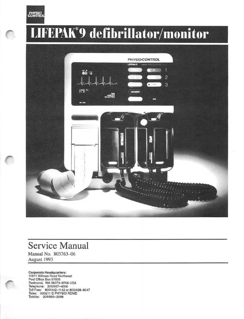
Physio Control LIFEPAK 15 V4 User manual

Title Service Process Work Instruction LIFEPAK 15 V4 CO2 Upgrade Page 1 of 38
Doc Type
Service Process Document
Doc ID
3333964
Doc Rev
A
Doc State
Released
State Date
3/22/2018
Reference Product DMR:
3313182
7000743_A.doc
This document is electronically signed in the Physio-Control, Inc. Product Lifecycle Management (PLM) System. Approvals can be
obtained from the PLM system which displays the selected approvers, their approval roles, and approval dates.
PROPRIETARY AND CONFIDENTIAL DOCUMENT FOR PHYSIO-CONTROL, INC. USE ONLY. This document is property of Physio-
Control and may not be used, reproduced, published or disclosed to others without authorization from Physio-Control.
Owner
Corporate
Attachments (Optional):
Qty
Pages
Page Sequencing
Change Description
Initial release.
Title Service Process Work Instruction LIFEPAK 15 V4 CO2 Upgrade Page 2 of 38
Doc Type
Service Process Document
Doc ID
3333964
Doc Rev
A
Doc State
Released
State Date
3/22/2018
Reference Product DMR:
3313182
7000743_A.doc
Purpose:
This instruction guides the Field Service Representative through the update process to add the CO2 feature to a LIFEPAK®15 version 4
monitor/defibrillator.
Scope:
This upgrade is for 3313182-All (Version 4), LIFEPAK 15 V4 monitor/defibrillators that do not previously have the End-Tidal Carbon Dioxide (CO2)
monitoring feature installed.
These instructions are intended for authorized field service personnel who have reviewed the upgrade procedure and who are familiar with the
LIFEPAK 15 device. The LIFEPAK 15 V4 Service Manual and the applicable Performance Inspection Procedure will be used in conjunction with this
Service Upgrade Process Work Instruction.
When installing multiple upgrades into a LIFEPAK 15 V4, the CO2upgrade should be the first upgrade installed.
All upgrades that include V4 software have the voice recorder enabled. This will be performed using the Combined Software Configurator Loader
(CSCL) configuration steps at the end of this upgrade.
Training:
As a prerequisite, only personnel that have completed LIFEPAK 15 V4 monitor/defibrillator repair training are allowed to perform this upgrade on a
LIFEPAK 15 V4 device. An individual will be considered fully trained when they meet the prerequisite, and read and understand of this document in
the Quality Management System (QMS).
Tools Required: (substitution of equivalent or better equipment allowed)
Computer – Win 7, equivalent or better.
LIFEPAK 15 To PC Interconnect Cable 11230-000005, 11230-000020, or 11996-000369.
Torque Driver – Hand Operation, with an adjustable range of 5 – 12 in-lbs.
Driver Bits – P1 (2”minimum shaft), P2 (5” minimum shaft), Torx, T-15 (2” minimum shaft).
Fixture Assembly, Capacitor Discharger 3012102 or 2673832.
Tools defined in the PIP - TCP sections of LIFEPAK 15 PIP Test Procedure, 3207841 or in Test Procedure, CAPIP, 3301593.
All tools requiring calibration should be calibrated and within their calibration cycle dates.
•Torque Driver conversions – 4 in-lbs. = 45 cNm, 6.8 in-lbs. = 77 cNm, 10 in-lbs. = 113 cNm
Documentation Required:
AHA Software Update Instruction 3333250
Instructions for use, Combined Service Configurator Loader 3206073
LIFEPAK 15 PIP/TCP Manual Procedure 3207841
Title Service Process Work Instruction LIFEPAK 15 V4 CO2 Upgrade Page 3 of 38
Doc Type
Service Process Document
Doc ID
3333964
Doc Rev
A
Doc State
Released
State Date
3/22/2018
Reference Product DMR:
3313182
7000743_A.doc
LIFEPAK 15 Service Manual, CD 3316924 (V4)
Work Instructions – CAPIP Test (where applicable) 3301593
Device Compliance Tool (where available) 3316610
Instructions, Setup Mode, LP15, V2, V4 3306226
Materials Required:
Kit – Upgrade, CO2 For LP15 V1, V2, V4, ROHS 43998-000007
Doc
ID:
3333964 Rev: ATitle: Service Process Work Instruction LIFEPAK 15 V4 CO2 Upgrade 4 of 38
Work
1
1
st
Verify
2
2nd Verify
Tool
!
Caution
Shock
Hazard
E
N
S
W
Orient
Clean
Scan
7000743_A
1. Verify the Device Serial Number
Verify that the device’s serial number label matches the serial
number listed in the upgrade kit documentation.
2. Initial Power-Up Check
Install a fully charged battery onto the LIFEPAK 15
monitor/defibrillator. Press the ON key. Verify that the device
powers up with no service indicator light. If the service
indicator light is illuminated, do not proceed with this
upgrade, and repair according to the appropriate LIFEPAK
15 monitor/defibrillator repair process. If the service indicator
light is not illuminated, continue with the upgrade.
3. Downloading Device Data (Pre-Service Report
Download)
NOTE: For International, Use your normal service reporting
process to document the service activity.
3.1 Perform a Pre-download before proceeding with the
upgrade using the Device Compliance Tool (DCT).
3.2 Turn the device off.
Doc
ID:
3333964 Rev: ATitle: Service Process Work Instruction LIFEPAK 15 V4 CO2 Upgrade 5 of 38
Work
1
1
st
Verify
2
2nd Verify
Tool
!
Caution
Shock
Hazard
E
N
S
W
Orient
Clean
Scan
7000743_A
4. Disassembling the Case
4.1 If applicable, remove carrying case.
4.2 Remove all cables and patient connections, and then
remove the batteries.
4.3 Remove and discard the four front mounting screws
(21300-007253) from the bumpers (Torx-15).
4.4 Remove and discard the four rear mounting screws
(21300-007253) from the bumpers (Torx-15).
4.5 Remove the bumpers (21300-007356 and 21300-
007010) from the case and set aside.
Remove Screws
(4 places)
Remove Screws
(4 places)
Doc
ID:
3333964 Rev: ATitle: Service Process Work Instruction LIFEPAK 15 V4 CO2 Upgrade 6 of 38
Work
1
1
st
Verify
2
2nd Verify
Tool
!
Caution
Shock
Hazard
E
N
S
W
Orient
Clean
Scan
7000743_A
4. Disassembling the Case (continued)
4.6 Lay the defibrillator face down on a protective
surface to prevent damage, and then remove the
14 case screws (21300-000777). Discard the
screws.
4.7 Holding the case halves together, position the device on
your work surface. Lift the front case assembly slightly
above the rear to access the connecting cables.
Remove Screws
(7 places)
Remove Screws
(5 places)
Remove Screws
(2 places)
Doc
ID:
3333964 Rev: ATitle: Service Process Work Instruction LIFEPAK 15 V4 CO2 Upgrade 7 of 38
Work
1
1
st
Verify
2
2nd Verify
Tool
!
Caution
Shock
Hazard
E
N
S
W
Orient
Clean
Scan
7000743_A
4. Disassembling the Case (continued)
4.8 Disconnect the P2 system/interface flex cable
connector (W04) from the system PCB in the rear case.
4.9 Disconnect the P23 therapy ribbon cable connector
(W11) in the front case from the from the therapy PCB.
4.10Disconnect the P21 therapy cable connector (W11) from
the Therapy PCBA.
4.11Separate the front and rear case halves.
Disconnect P2 –
System/Interface
Flex. Lift
connector tab to
disconnect cable.
Disconnect
Therapy Cable
Disconnect
Therapy Ribbon
Cable
Doc
ID:
3333964 Rev: ATitle: Service Process Work Instruction LIFEPAK 15 V4 CO2 Upgrade 8 of 38
Work
1
1
st
Verify
2
2nd Verify
Tool
!
Caution
Shock
Hazard
E
N
S
W
Orient
Clean
Scan
7000743_A
4. Disassembling the Case (continued)
DANGER
SHOCK HAZARD: Lethal voltages may be present even
without operator action. Always discharge the energy
storage capacitor prior to servicing.
4.12Before continuing any further, discharge the energy
storage capacitor using the discharge tool.
4.13 To use the capacitor discharge tool:
4.13.1 Place one probe on a discharge point and hold it
steady.
4.13.2 Place the other probe on the remaining discharge
point and hold both probes steady.
4.13.3 Observe the neon lamp inside the capacitor discharge
tool. If a charge of approximately 90 volts is present,
the neon lamp will light.
4.13.4 Continue holding the probes on the points indicated
for at least 30 seconds after the neon lamp is no
longer lit.
DISCHARGE
STORAGE
CAPACITOR
Doc
ID:
3333964 Rev: ATitle: Service Process Work Instruction LIFEPAK 15 V4 CO2 Upgrade 9 of 38
Work
1
1
st
Verify
2
2nd Verify
Tool
!
Caution
Shock
Hazard
E
N
S
W
Orient
Clean
Scan
7000743_A
5. Removing the Parameter Bezel from rear case.
5.1 Remove the parameter bezel label from the bezel and
discard.
5.2 Remove and discard the CO2 spacer label (21300-
007362) from Bezel.
5.3 Remove the two bezel mounting screws (21300-006965).
Discard the screws.
5.4 Disconnect the ECG connector cable, J6.
5.5 If present, disconnect the IP connector cable of the IP wire
harness, J7.
5.6If present, disconnect the temperature connector of the
temperature cable (W35) J7.
5.7 Lift out the parameter bezel (21330-001211) from the rear
case.
Remove
Parameter
Bezel Label
Remove
Screws
(2 places)
Remove CO2
Spacer Label
21300-007362
Disconnect J6 and
J7 (if present)
Connectors
Parameter
Bezel
21330-001211
Doc
ID:
3333964 Rev: ATitle: Service Process Work Instruction LIFEPAK 15 V4 CO2 Upgrade 10 of 38
Work
1
1
st
Verify
2
2nd Verify
Tool
!
Caution
Shock
Hazard
E
N
S
W
Orient
Clean
Scan
7000743_A
6. Removing the System/Therapy PCB Assembly
6.1 J1 – Press the connector locking tabs and disconnect the
power/system PCB cable (W01).
6.2 J4 – Disconnect the USB flex connector (W14).
6.3 Remove the seven screws (21300-001038) and three
screws with washer (21300-007297) that secures the
system PCB to the rear case. Discard all screws and
washers.
Note: The screw that is in the EMI shield can easily be missed
as part of screw removal. Ensure that all screws are removed
prior to lifting the system/therapy PCB assembly.
Disconnect J4
USB Flex
Connector
Disconnect J1
Power/ System
Cable
Remove screw
with cap. washer
(3 places)
Remove
screws
(7 places)
Doc
ID:
3333964 Rev: ATitle: Service Process Work Instruction LIFEPAK 15 V4 CO2 Upgrade 11 of 38
Work
1
1
st
Verify
2
2nd Verify
Tool
!
Caution
Shock
Hazard
E
N
S
W
Orient
Clean
Scan
7000743_A
6. Removing the System/Therapy PCB Assembly
(continued)
6.4Carefully lift system/therapy PCB assembly to gain access
to the cables below.
6.5 Disconnect P22 of the therapy cap wire harness (W24)
from J22 of Cap discharge PCB assembly.
6.6 Disconnect the J20 connector on the therapy PCB
(power/PCB therapy cable W02).
6.7 Lift the system/therapy board assembly out from the rear
case. Store Assembly in ESD safe container.
Disconnect
from J20 of
Therapy PCB
Disconnect P22
to PCB ASSY-
CAP Discharge
Doc
ID:
3333964 Rev: ATitle: Service Process Work Instruction LIFEPAK 15 V4 CO2 Upgrade 12 of 38
Work
1
1
st
Verify
2
2nd Verify
Tool
!
Caution
Shock
Hazard
E
N
S
W
Orient
Clean
Scan
7000743_A
7. Removing the Parameter Bezel
7.1 Disconnect power/therapy cable (WO2) from J8 of Power
PCB.
7.2 Remove the OEM shield (21300-008127).
Disconnect Power/
Therapy Cable
21300-001373
Remove OEM Shield
21300-008127
J8
connection
Doc
ID:
3333964 Rev: ATitle: Service Process Work Instruction LIFEPAK 15 V4 CO2 Upgrade 13 of 38
Work
1
1
st
Verify
2
2nd Verify
Tool
!
Caution
Shock
Hazard
E
N
S
W
Orient
Clean
Scan
7000743_A
7. Removing the Parameter Bezel (continued)
7.3 Disconnect the power/contact PCBA, P12 flex cable (W05)
from the power board at J12.
7.4 Remove the power/system cable from the power board at
J17.
Disconnect Cable
Assy – Pwr/Sys
21300-007456
Disconnect Power
/Contact PCBA P12
Flex Cable
J12
connection
J17
connection
Doc
ID:
3333964 Rev: ATitle: Service Process Work Instruction LIFEPAK 15 V4 CO2 Upgrade 14 of 38
Work
1
1
st
Verify
2
2nd Verify
Tool
!
Caution
Shock
Hazard
E
N
S
W
Orient
Clean
Scan
7000743_A
7. Removing the Parameter Bezel (continued)
7.5 If present, disconnect the SpO2/OEM cable (W21).
7.6 If present, remove the NIBP connector retainer clip and
disconnect the NIBP/OEM cable (W27).
CAUTION
POSSIBLE COMPONENT DAMAGE: The SpO2
connector flex cable can be damaged during
disassembly. If SpO2 connector is damaged
replace the SpO2 flex cable using the Masimo
SpO2 Panel Mount Cable Repair Kit (40577-
000025).
7.7 Carefully disconnect the SpO2 connector flex cable (W22)
from J1 of SpO2 PCB.
OEM PCB
at J26
W22 SpO2 flex
cable
J1 connection
W21 SpO2/OEM
cable
W27 NIBP/OEM
cable and retainer
clip
Doc
ID:
3333964 Rev: ATitle: Service Process Work Instruction LIFEPAK 15 V4 CO2 Upgrade 15 of 38
Work
1
1
st
Verify
2
2nd Verify
Tool
!
Caution
Shock
Hazard
E
N
S
W
Orient
Clean
Scan
7000743_A
8. Removing the OEM PCB
8.1 Power PCB: Disconnect the battery pins/power PCB cable
(W10) at J11, and auxiliary power cable (W09) at J15-A and
J15-B from the Power PCB.
8.2 Remove the nylon standoff from the OEM PCB.
8.2 Remove the four mounting screws. Discard the screws.
8.4 Lift the right edge of the OEM PCB upward slightly, and
then slide the PCB to the right (toward the capacitor) to
disengage the direct connection between the OEM PCB at
(J25) and the power PCB at J16.
8.5 Lift the OEM board from the rear case. Store the OEM
PCB in an ESD safe container.
J15-B connection
(W09) cable
J11 connection
(W10) cable
J15-A connection
(W09) cable
OEM PCB
(J25)
Power PCB
at (J16)
Remove 4
Screws
Remove
nylon
standoff
Doc
ID:
3333964 Rev: ATitle: Service Process Work Instruction LIFEPAK 15 V4 CO2 Upgrade 16 of 38
Work
1
1
st
Verify
2
2nd Verify
Tool
!
Caution
Shock
Hazard
E
N
S
W
Orient
Clean
Scan
7000743_A
9. Removing the OEM Modules bracket assembly
9.1 Remove the three mounting bracket screws. Discard the
screws.
9.2 If present, disconnect the NIBP inlet tube. Lift the
assembly as needed.
9.3Lift the mounting bracket and cover from the rear case.
9.4If present, For the NIBP option dissasembly, remove the
NIBP cable (W27) from the cable guide on bracket cover.
9.5Remove the four screws from the bracket cover (21330-
001195) and lift off the cover. Discard the screws.
Remove NIBP
cable from guide
Shown with
NIBP installed
NIBP cable
Then
Remove 4
Screws
Remove 3
Screws
NIBP inlet tube
Doc
ID:
3333964 Rev: ATitle: Service Process Work Instruction LIFEPAK 15 V4 CO2 Upgrade 17 of 38
Work
1
1
st
Verify
2
2nd Verify
Tool
!
Caution
Shock
Hazard
E
N
S
W
Orient
Clean
Scan
7000743_A
10.Installing the CO2 Inlet Connector Cable (W28)
10.1 Set the CO2 connector adapter (21300-001548) in place
on the face of the bezel.
10.2 Place the new CO2 connector retainer (21300-007998)
and new seal (21300-001314) in place on the underside of
the bezel and tighten together with four new screws
(21300-007353), torque to 2 in-lbs. using a P0 bit.
CAUTION
POSSIBLE MOISTURE LEAK When installing the
W28 cable, apply 2 in-lbs. of torque when installing
the screw retaining the W28 cable. This is to help
prevent the ingress of fluids.
10.3 Slide the CO2 inlet connector cable (W28) (21300-
001529) into the new CO2 connector retainer.
CO2 Seal
21300-001314
T
O
R
Q
U
E
T
O
R
Q
U
E
T
O
R
Q
U
E
2.0 In-lbs.
CO2 Connector
Retainer
21300-007998
CO2 Connector
Adapter
21300-001548
Screw
21300-007353
(4 places)
CO2 inlet
connector
Doc
ID:
3333964 Rev: ATitle: Service Process Work Instruction LIFEPAK 15 V4 CO2 Upgrade 18 of 38
Work
1
1
st
Verify
2
2nd Verify
Tool
!
Caution
Shock
Hazard
E
N
S
W
Orient
Clean
Scan
7000743_A
11. Installing the CO2 Modules
NOTE: Shown with NIBP installed.
11.1 Attach the CO2 module (21330-001535) to the mounting
bracket with four new screws (21300-006251); torque to
4.0 in-lbs.
11.2 Connect the CO2 adapter cable (21330-000237) (W30) to
the A23 CO2 PCB at J1.
11.3 Connect the OEM PCB/CO2 module cable (21330-
001217) (W26) to the A23 CO2 PCB at J4.
CAUTION
POSSIBLE SKIN BURNS:Do not open the CO2
scrubber device (part of the CO2 module).
Scrubber material may cause caustic burns. If
scrubber material comes in contact with skin, rinse
the area of contact thoroughly with water. If
scrubber material comes in contact with eyes, flush
eyes with water for 15 minutes, and then seek
immediate medical attention.
OEM/CO2 Cable
21330-001217
CO2 Adapter cable
21330-000237
NIBP Module
CO2 Module
21330-001535
T
O
R
Q
U
E
T
O
R
Q
U
E
T
O
R
Q
U
E
4.0 In-lbs.
Screws
21300-006251
(4 places)
Doc
ID:
3333964 Rev: ATitle: Service Process Work Instruction LIFEPAK 15 V4 CO2 Upgrade 19 of 38
Work
1
1
st
Verify
2
2nd Verify
Tool
!
Caution
Shock
Hazard
E
N
S
W
Orient
Clean
Scan
7000743_A
11. Installing the CO2 Modules (continued)
11.4For the CO2 option, route the CO2 tubing and CO2
adapter cable. Ensure that the cable and tubing are not
pinched when installing the bracket cover.
11.5 If present, route the NIBP cable through the cable mount
on side of bracket cover. Ensure that the cable and tubing
are not pinched when installing the bracket cover.
11.6 Attach the bracket cover to the OEM bracket with 4 new
screws (21300-006251), torque to 4.0 in-lbs.
11.7 Attach the CO2 module cable (W26) to the microwire
saddle clip as shown.
CO2 Option
NIBP Option
T
O
R
Q
U
E
T
O
R
Q
U
E
T
O
R
Q
U
E
4.0 In-lbs.
OEM/CO2 module
cable (W26)
CO2 adapter
cable (W30)
NIBP hose and
cable routing
Microwire saddle
clip
Screws
21300-006251
(4 places)
Doc
ID:
3333964 Rev: ATitle: Service Process Work Instruction LIFEPAK 15 V4 CO2 Upgrade 20 of 38
Work
1
1
st
Verify
2
2nd Verify
Tool
!
Caution
Shock
Hazard
E
N
S
W
Orient
Clean
Scan
7000743_A
11. Installing the CO2 Modules (continued)
11.8 If present, Carefully reconnect the SpO2 connector flex
cable (W22) from J1 of SpO2 PCB.
11.9 Connect the exhaust tube to the rear case outlet
connector.
11.10 Place the OEM bracket into the rear case and secure
with the three new mounting screws (21300-007297);
torque to 6.8 in-lbs.
11.11 Connect CO2 module tube to CO2 inlet tube.
11.12Connect CO2 inlet cable (W28) to CO2 adapter cable
(W30).
Note: (W28) should be routed under bracket with CO2 inlet
tube.
Connect module
tube to inlet tube
Connect CO2
exhaust tubing
T
O
R
Q
U
E
T
O
R
Q
U
E
T
O
R
Q
U
E
6.8 In-lbs.
W28-W30 CO2 inlet
cable connector
Screws
21300-007297
(3 places)

Other manuals for LIFEPAK 15 V4

1

Other Physio Control Medical Equipment manuals
Physio Control LIFEPAK 15 User manual

Physio Control

Physio Control LIFEPAK 15 User manual

Physio Control LIFEPAK CR PLus User manual

Physio Control

Physio Control LIFEPAK CR PLus User manual

Physio Control Lifepak CR2 LIFELINKcentral User manual

Physio Control

Physio Control Lifepak CR2 LIFELINKcentral User manual

Physio Control LIFEPAK 20 User manual
Physio Control

Physio Control LIFEPAK 20 User manual

Physio Control LIFEPAK 15 User manual
Physio Control

Physio Control LIFEPAK 15 User manual

Physio Control HeartStart MRx User manual

Physio Control

Physio Control HeartStart MRx User manual

Physio Control Lifepak 1000 User manual

Physio Control

Physio Control Lifepak 1000 User manual

Physio Control LIFEPAK 15 Technical manual

Physio Control

Physio Control LIFEPAK 15 Technical manual

Physio Control LIFEPAK 15 User manual

Physio Control

Physio Control LIFEPAK 15 User manual

Physio Control LIFEPAK 15 V4 User manual

Physio Control

Physio Control LIFEPAK 15 V4 User manual

Physio Control Lifepak CR2 LIFELINKcentral User manual

Physio Control

Physio Control Lifepak CR2 LIFELINKcentral User manual

Physio Control LIFEPAK CR PLus User manual

Physio Control

Physio Control LIFEPAK CR PLus User manual

Physio Control LUCAS 3 User manual

Physio Control

Physio Control LUCAS 3 User manual

Physio Control LIFEPAK 500 User manual
Physio Control

Physio Control LIFEPAK 500 User manual

Physio Control LIFEPAK 12 User manual

Physio Control

Physio Control LIFEPAK 12 User manual

Physio Control Lifepak CR2 LIFELINKcentral User manual

Physio Control

Physio Control Lifepak CR2 LIFELINKcentral User manual

Physio Control LIFEPAK 15 V2 User manual

Physio Control

Physio Control LIFEPAK 15 V2 User manual

Physio Control LIFEPAK 15 User manual

Physio Control

Physio Control LIFEPAK 15 User manual

Physio Control lucas 2 User manual

Physio Control

Physio Control lucas 2 User manual

Physio Control LIFEPAK 15 User manual

Physio Control

Physio Control LIFEPAK 15 User manual

Physio Control LIFEPAK 15 User manual

Physio Control

Physio Control LIFEPAK 15 User manual

Physio Control LIFEPAK 20 User manual

Physio Control

Physio Control LIFEPAK 20 User manual
Physio Control LIFEPAK 20 User manual

Physio Control

Physio Control LIFEPAK 20 User manual

Physio Control lucas 2 Reference guide

Physio Control

Physio Control lucas 2 Reference guide

Popular Medical Equipment manuals by other brands

Masimo SafetyNet Alert user manual

Masimo

Masimo SafetyNet Alert user manual

WOK Mighty Rest user manual

WOK

WOK Mighty Rest user manual

Mediroyal NRX STRAP instructions

Mediroyal

Mediroyal NRX STRAP instructions

dynarex MD300C25 user manual

dynarex

dynarex MD300C25 user manual

Mopec Maestro MG1000 Series Installation, service and user instructions

Mopec

Mopec Maestro MG1000 Series Installation, service and user instructions

CoolHealth TargetCool RM-DT02W user manual

CoolHealth

CoolHealth TargetCool RM-DT02W user manual

Wissner-Bosserhoff Linet ProphyCair User manual and technical description

Wissner-Bosserhoff

Wissner-Bosserhoff Linet ProphyCair User manual and technical description

Medrad Mark 7 Arterion Instructions for use

Medrad

Medrad Mark 7 Arterion Instructions for use

Vielight X-Plus operating instructions

Vielight

Vielight X-Plus operating instructions

inbody BPBIO320S user manual

inbody

inbody BPBIO320S user manual

ResMed AirFit N30 user guide

ResMed

ResMed AirFit N30 user guide

Weinmann Homecare CPAP 20e manual

Weinmann

Weinmann Homecare CPAP 20e manual

GF John Bunn O2 Premier JB0160-010 user manual

GF

GF John Bunn O2 Premier JB0160-010 user manual

Graseby omnifuse instruction manual

Graseby

Graseby omnifuse instruction manual

Sri PXS-710D Installation and operation manual

Sri

Sri PXS-710D Installation and operation manual

Basko Healthcare Stomacare EasyCut Instructions for use

Basko Healthcare

Basko Healthcare Stomacare EasyCut Instructions for use

Mobius Bionics LUKE Arm user guide

Mobius Bionics

Mobius Bionics LUKE Arm user guide

Orliman Pediatric OP1197 Use and maintenance instructions

Orliman

Orliman Pediatric OP1197 Use and maintenance instructions

manuals.online logo
manuals.online logoBrands
  • About & Mission
  • Contact us
  • Privacy Policy
  • Terms and Conditions

Copyright 2025 Manuals.Online. All Rights Reserved.