Pi Supply Pi PoE Switch HAT User manual

Pi Supply
The Maker Emporium
https://learn.pi-supply.com
Pi PoE Switch HAT Quick Start And FAQ
Getting started
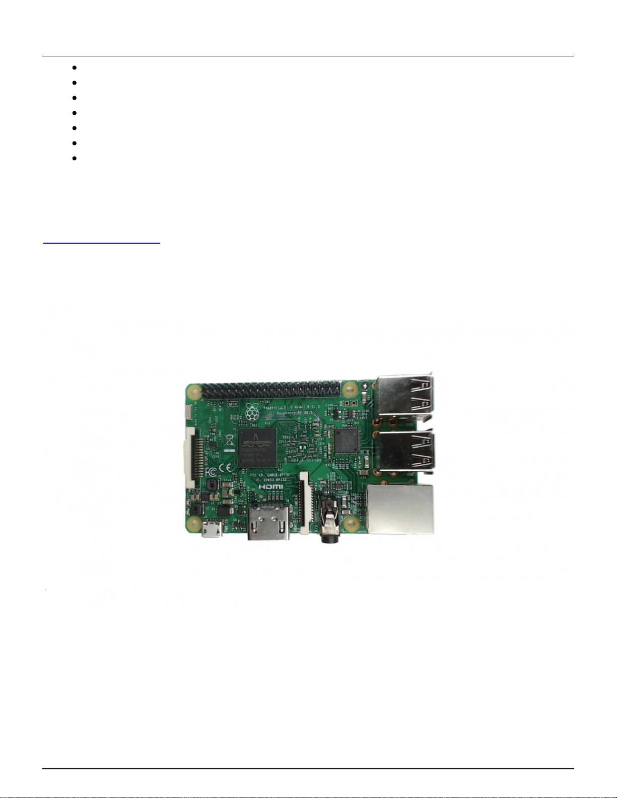
The Pi PoE Switch HAT is an add on board for the Raspberry Pi that brings the Pi Supply Switch
technology together with PoE all in one fantastic package! You can now power your Raspberry Pi
and provide an Ethernet connection in any location with just a single cable. Perfect for removing
the clutter of wires and for reliable use in remote locations.
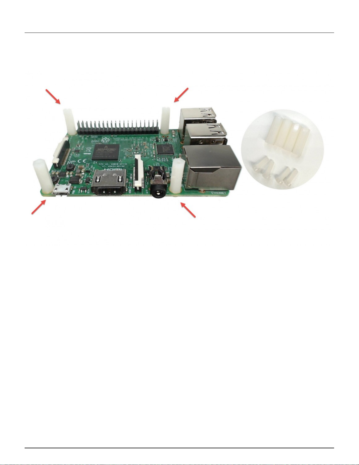
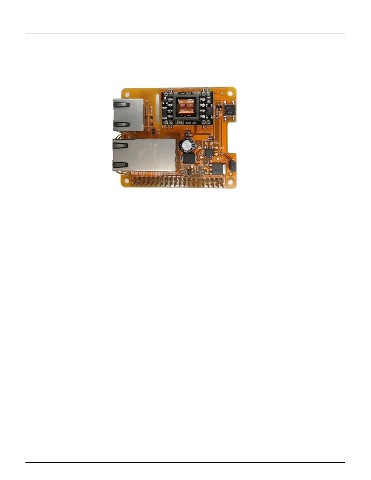
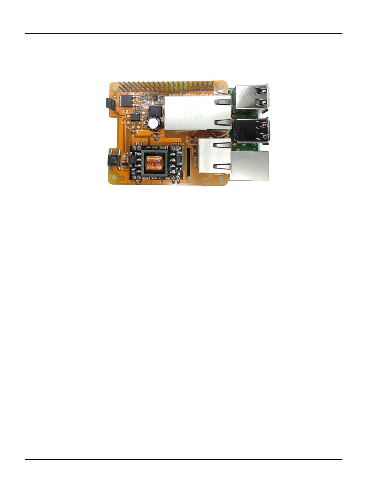
This guide will show you how to assemble the Pi PoE Switch HAT, set it up in its case and discuss
some of the most common issues and questions.
Kit contents
1 / 22

Pi Supply
The Maker Emporium
https://learn.pi-supply.com
Inside the box you should have received the following items:
1 Pi PoE Switch HAT board
8 Plastic bolts
4 Plastic spacers
1 Ethernet cable
2 SMD resistors
3 Stickers
1 Info card
Board Assembly
Step 1 - Unpack your Raspberry Pi.
Step 2 - Install the spacers on the Raspberry Pi as shown here holding them with 4 plastic bolts
from underneath the Pi.
The bolts should be screwed in with a PH0 screwdriver. In some cases the bolts could be slightly
hard to screw in the spacers. Use a metal bolt to help loosing the rim in the spacer so that the
2 / 22

Pi Supply
The Maker Emporium
https://learn.pi-supply.com
plastic bolt will oppose less resistance during assembly.
Step 3 - Get the Pi PoE from its anti-static bag.
3 / 22

Pi Supply
The Maker Emporium
https://learn.pi-supply.com
Step 4 - Place the Pi PoE on top of the Raspberry Pi by gently pushing the female header onto the
Raspberry Pi male header.
4 / 22

Pi Supply
The Maker Emporium
https://learn.pi-supply.com
Step 5 - Screw the last 4 plastic bolts to hold the Pi PoE HAT in place.
5 / 22

Pi Supply
The Maker Emporium
https://learn.pi-supply.com
Remember that the power to the PiPoE from the managed switch or from the external injector
should only be applied after the Ethernet cables have been connected. Although the current
version of PiPoE has been designed to protect it from electrical spikes caused by plugging PoE
cables with power already present, it is best practice to connect cables with no power.
Case Assembly
The Pi PoE Switch HAT Case is the prefect enclosure for the Pi PoE Switch HAT and the
Raspberry Pi. It has been designed so that it can still allow access to the power button.
7 / 22

Pi Supply
The Maker Emporium
https://learn.pi-supply.com
Step 1 - After removing the protective plastic pull gently out the two sides of the bottom part of the
case to unhook the top.
8 / 22

Pi Supply
The Maker Emporium
https://learn.pi-supply.com
This should allow you to detach the top cover and easily take a part the case.
Within the case you will find 4 rubber feet and a plastic bit used to provide access to the Pi PoE
power button. Here is how it will look like once opened.
9 / 22

Pi Supply
The Maker Emporium
https://learn.pi-supply.com
Step 2 - Insert the plastic button extender through the hole of the top part of the case.
10 / 22

Pi Supply
The Maker Emporium
https://learn.pi-supply.com
Step 3 – To install the rubber feet on the bottom part of the case you will either have to push and
twist them through one of the 4 the holes or help yourself with a small screwdriver to tuck in the top
part of the feet within the hole as shown on the left. Be careful not to cut through the feet and rather
than using the tip of the screwdriver use the flat surface to push the head of rubber foot in.
11 / 22

Pi Supply
The Maker Emporium
https://learn.pi-supply.com
Step 4 - Insert the Raspberry Pi and the Pi PoE in the bottom part of the case by first placing the
USB connectors in.
12 / 22

Pi Supply
The Maker Emporium
https://learn.pi-supply.com
The PCBs of the two boards should be aligned within the grooves of the panel as shown in the
picture.
13 / 22

Pi Supply
The Maker Emporium
https://learn.pi-supply.com
Step 5 - Take the small Ethernet cable and connect it between the Raspberry Pi and the Pi PoE.
14 / 22

Pi Supply
The Maker Emporium
https://learn.pi-supply.com
Step 6 - Connect the Ethernet cable coming from the PoE switch or from the injector.
15 / 22

Pi Supply
The Maker Emporium
https://learn.pi-supply.com
Step 7 - Slide the top part of the case back in place. As you do that gently pull out each side of the
top part of the case so to allow the connectors of the Raspberry Pi to slot into place.
16 / 22

Pi Supply
The Maker Emporium
https://learn.pi-supply.com
At this point the Pi PoE Switch HAT is ready to be used.
Note that the case has been designed with wall fixing features.
17 / 22

Pi Supply
The Maker Emporium
https://learn.pi-supply.com
FAQ
Button, Jumper and Solder PAD
Button - SW1
To start the Raspberry Pi press SW1 for 2 seconds. To completely remove power to the Raspberry
Pi press SW1 for at least 15 seconds and until the red LED of the Pi will switch off.
Jumper - CN2
With the jumper in place to power up the Raspberry Pi you will need to operate SW1, without the
jumper as soon as the PoE line receives power the board will power up the Raspberry Pi without
the need to use SW1. This is particularly ideal if the Raspberry Pi is in a remote location.
Solder Pad
18 / 22

Pi Supply
The Maker Emporium
https://learn.pi-supply.com
On the reverse of the board you can find a solder pad to allow you to add flexibility to the Pi PoE by
for example use a custom made button to power on and off the Pi PoE.
Optional Resistors
The Pi PoE main Ethernet connector comes with two LEDs which can be connected to GPIO
22,23,24. In order to do so you will have to solder the optional resistors provided. They need to be
placed on the reverse of the board where it reads R12 and R13.
19 / 22

Pi Supply
The Maker Emporium
https://learn.pi-supply.com
To drive the LEDs you will have to set the GPIOs as outputs. The LED on the left is a single green
LED whereas the one on the right is a dual green/amber LED. To drive the green LED on the left it
is sufficient to pull the corresponding GPIO 23 high, to turn it bring the GPIO low. For the dual LED
instead you will have to bring GPIO 22 high whilst having GPIO 24 low to turn on the green LED,
with GPIO 22 low and GPIO 24 high you will turn on the amber LED. The animation below
summarises the logic.
20 / 22
Table of contents