Page 1 of 2
MAN1808 Website: www.ampac.net Revision: 29 July 2009
“ Our aim is to provide ‘Consistently Excellent Service ’ in the eyes of our customers ”
GasRelease
System Remote Status Unit
Installation Guide Item Numbers: 2980-0001 and
2980-0002
Introduction
The Remote Status Unit (RSU) connects to the GasRelease panel and
provides remote system status indication, an LCD status display unit,
manual release of gas, a manual and automatic mode keyswitch and three
monitored inputs. RSUs can be either flush-mounted or surface-mounted.
Installation
Location and Fixing
The RSU must be mounted indoors on a dry, flat surface in an area that is
well ventilated. Ideally the LED indicators and LCD should be at eye level
and the ambient light level should allow the status of indicators to be
clearly seen.
Take the RSU out of its packing box. Using the Allen key (supplied in the
accessory pack) remove the RSU’s front lid by undoing the four lid screws.
Note: If required, to protect the electronics from damage, the Connector
PCB (mounted in the RSU base) can be removed prior to first fix installation.
Simply unscrew its one retaining screw and slide the PCB off its four
mounting pillars.
Disconnect the telecoms-style connecting cable from PL1 on the PCB. Fix the RSU’s base securely onto a
wall using the four mounting holes provided. Assess the condition and construction of the wall and use
suitable screw fixings. Any dust or swarf created during the fixing process must be kept out of the RSU and
care must be taken not to damage any wiring or components.
Wiring
All wiring should be installed in accordance with the current edition of the IEE
Wiring Regs (BS7671), or the relevant national standards. Cables should be fed
into the RSU via the knockouts provided on the top of the base unit. Knockouts
should be removed with a sharp, light tap using a flat 6mm broadsided
screwdriver as shown in diagram (see right). Always ensure that if a knockout is
removed, the hole is filled with a good quality 20mm cable gland. Any unused
knockouts must be securely blanked off.
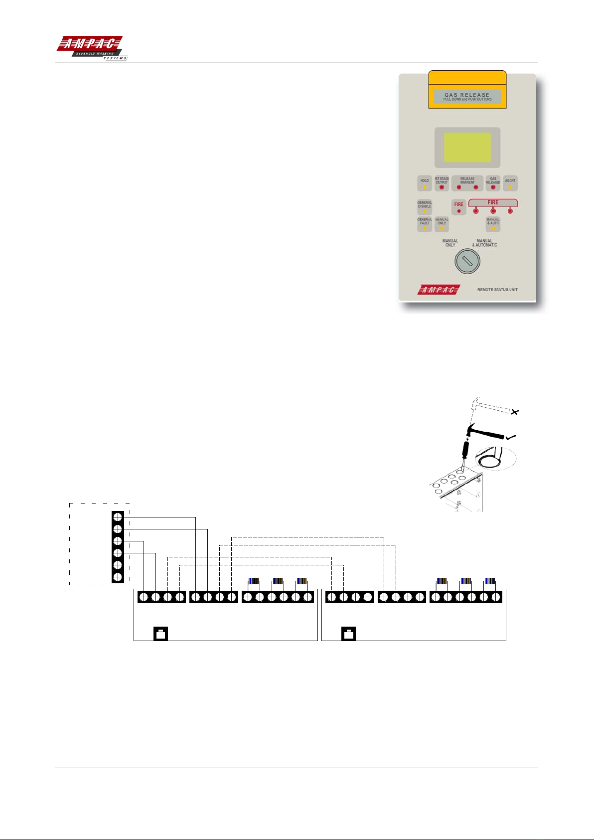
A B
DATA
CONN3
+
B
ABORT MODE
Gas Release Panel
Remote Status Unit 1
6K8 EOL
Remote Status Unit
-
A
PL1
EXTERNAL INPUTS
CONN1
HOLD
+
B
A
A B +24V 0V
SUPPLY
CONN2
0V +24V --- ++ AB
DATA
CONN3 ABORT MODE
Remote Status Unit n (Up to 8 max)
6K8 EOL
PL1
EXTERNAL INPUTS
CONN1
HOLD
+
A B +24V 0V
SUPPLY
CONN2
0V +24V - -
- ++
Connects to PL1
on display board Connects to PL1
on display board
Figure 1 – Typical RSU Circuit Wiring
The first RSU connects to the Remote Status Unit connector terminals on the Main Control PCB (mounted
inside the Gas Release panel) via a 4-wire connection (2-wire power, 2-wire RS485). The wiring is then
daisy-chained onto the remaining RSUs (see Fig.1). A maximum of eight RSUs can be connected to the Gas
Release panel. Three monitored input connections are available at the RSU: Hold, Abort, and Mode. A 6k8
EOL resistor (supplied in the accessory pack) must be connected across the terminals of the last device on


