manuals.online logo
Brands
  1. Home
  2. •
  3. Brands
  4. •
  5. ADTRAN
  6. •
  7. Control Unit
  8. •
  9. ADTRAN Total Access 300 Series User manual

ADTRAN Total Access 300 Series User manual

1
jobAid
DESCRIPTION
The Total Access®362S Single Family Unit (SFU) Optical Network
Terminal (ONT) is a Gigabit Passive Optical Network (GPON) ONT
with RF Overlay and Single Wire Return Device (SWRD) powering
(SFU ONT, P/N 4187712G2). The Total Access 300 Series has 2
POTS, and 2 Ethernet interfaces. The figure above illustrates the
SFU ONT inner enclosure. GPON technology provides a consistent
and common approach to advancing the public communications
network using:
♦Traditionaltelephoneservice[PlainOldTelephoneService(POTS)]
♦Highspeeddataservices(10/100/1000)
♦Videoservices
♦SWRDpoweringthroughETH 2(10/100)
ThisJobAidcoverstheelectronicsmodules(SFUONT)andhousings
listedinthefollowingtable:
NOTE
Refer to the Total Access 300 Series GigE SFU ONT with RF Overlay
and SWRD Powering Installation and Maintenance Guide (P/N
64187712G2-5) for more extensive installation instructions.
Total Access
362S
Description
1187712G2 Total Access 362S Electronics Module
Total Access
SFU Housings
Description
1187770G1 TotalAccessONTSpliceHousing
1187771G1 TotalAccessONTwithOptiTapHousing
RING
TIP
RING
TIP
FXS 0/1
FXS 0/2
ETH 0/1
ETH 0/2
POTS 2
ETH 1
CLEI
TIP RING
TEL. NUMBER
TIP RING
TIP RING
TIP RING
RF Connection
Surface
Mounting
Hole
Surface Mounting Hole
Hinge
Hinge
Security
Screw
Two-screw
Terminal
Bridges
Ethernet
Connections
Fiber Optic
Cable
Ground
Power
Ethernet Drop
POTS Drop
Ground and Power
Drop Callout
Ground Drop
Fiber Drop
ETH 2
SWRD Powering
Total Access 300 Series
GigE SF ONT
with RF Overlay and SWRD Powering
FRONT PANEL LEDS
INSTALLATION
AfterunpackingtheSFUONT,inspectitfordamage.Ifdamageisnoted,
fileaclaimwiththecarrierandthencontactADTRAN.Formoreinfor‐
mation,refertothewarranty.
Required Tools and Supplies
StandardtechniciantoolsareusedforinstallingSFUONT.Foracomplete
listofspecialtools,suppliesandtestequipment,refertotheTotalAccess
300SeriesGigESFUONTwithRFOverlayandSWRDPoweringInstallation
andMaintenanceGuide(P/N64187712G2‐5).
Mount the Enclosure
Completethefollowingstepstomounttheenclosure:
1. Chooseaverticalsurfacenearanapprovedground,butawayfrom
downspouts,permanentwatersprinklers,orotherwatersources.
Thesubscribershouldhaveeasyaccessfortesting.
2. Usethetopandbottomexternalmountingholesasatemplateto
markfastenerlocations.Usealeveltoensuretheunitislevelto
preventwarping.
3. Pre‐drillthemarkedlocationsandinstallfastenersoranchors
appropriatetothemountingsurface(eachanchorratedto15lbs
minimum).
4. MounttheSFUONTtothesideofthesubscriber’spremise.
TheElectronicsModuleisinstalledinthehousingandswingsopenon
hinges.Toreleasethismodule,loosentheSecurityScrew(refertothe
illustrationonthefirstpage)andswingtheelectronicsModuletotheleft.
CAUTION
!
Donotuseaknifetocuttheopeningintherubbergrommets.Thismay
resultinanexcessivelylargeholeandcompromisetheintegrityofthe
unitallowingmoistureintotheunit.
Label Status Description
POWER {
z
Off
Green
Nopower
PowerisOn
NETWORK
STATUS
z
z
z
Green
Yellow
Red
OLThasactivatedtheONT
OLTisdiscoveringandranging
TheOLThasshutdowntheONT
SWRD POWER
(ETH2)
{
z
Off
Green
Powerdisabled
PowerisOn
POTS 1 and 2 {
z
2
Off
Green
GreenFlashing
Fiberisdisconnected,GPONinter‐
faceisdown,orbothportsareidle
ordisabled
AtleaseoneportisOffHook
AtleastoneportisRinging
ETH 1 and 2 {
z
z
Off
Green
YellowFlashing
Linkisdown,noactivity,orAdmin‐
istrativelyShutdown
Linkisup
TXorRXactivity
Product P/N: 4187712G2
Issue Date: September 2010
Document P/N: 64187712G2-22C
264187712G2-22C
7. ReplacetherubbergrommetwhileclosingtheElectronicsModule.
ThisplaceslessstressonthewiringandallowstheElectronics
Moduletoclosewithoutpinchinganywiring.
Route OptiTap Fiber Drop Cable
Refertotheillustrationbelowforfiberinstallations:
1. PlacetheOptiTapfiberdropinthesamerubbergrommetchannel
asthegroundcable.Thegroundcableshouldbe“behind”theOpti‐
Tapfiber.
2. ConnecttheOptiTapfiber.
3. PlacetheOptiTapconnectorinthecut‐outinthehousing.
4. Connectthefibercabletotheconnectoronthebottomofthe
ElectronicsModule.
5. RoutethecablesothatwhentheElectronicsModuleisclosed,the
fiberisnotpinched.
NOTE
TherearewireroutingclipsonthelowerrightoftheElectronicsModule
housing.Itisrecommendedthatthesenotbeused.Routethepowerwires
sothattheyarenotpinchedwhentheElectronicsModuleisclosed.
Install SC/APC Optical Connection
NOTE
RefertotheTotalAccess300SeriesGigESFUONTwithRFOverlayand
SWRDPoweringInstallationandMaintenanceGuide(P/N64187712G2‐5)for
informationoninstallingtheSC/APCopticalconnection.
Toinstalltheopticalconnector,completethefollowing:
1. Withtheelectronicsmoduleswungopen,routethefiberthrough
themostdirectgrommetentranceandconnectittotheappropriate
SC/APCopticalconnection.
2. Checkthattherearenobendsinthefiberlessthan30mm(1.2
inches)radiusor60mm(approximately2.5inches)indiameter.
Whenthemaintenancedoorisclosed,itshouldnotcomeincontact
withthefiber.
Local Power Source Wiring
TheSFUONTneedstobepoweredbyaULListedPowerSupplysuitable
fortheapplicationwithOutputatLPSLevels.
ThisSFUONTshouldonlybeoperatedfromthetypeofcertified/listed
powersupplyrecommendedbythepowersupplymanufacturer.
Do not tie wrap
the optical cable.
Route it as shown.
Ground Drop
Rubber Grommet
Tie Wrap
Opti-Tap Connector
+12VDC
12VRTN
SIGRTN
ONBAT
REPBAT
BATMIS
LOWBAT
7
6
5
4
3
2
1
Ground Connection
Refertotheillustrationbelowandintheoppositecolumntoinstallthe
groundconnection:
1. Removetherubbergrommetfromthehousingandinserta#6solid
coppergroundwirethroughtherubbergrommet.
2. Replacetherubbergrommetinthehousing.
3. Routethegroundwire12inchesbelowfinishedgradebythe
shortestandmostdirectroutetotheACpowergroundsystem
MultiGroundedNeutral(MGN)ofthecustomerpremises.Ensure
thewireisfreeofanysharpbends.
4. Attachthegroundwiretothesideofthesubscriber’spremiseswith
stainlesssteelhalfmoonclampsortie‐wrapthegroundwiretothe
riserconduitoftheBuriedFiberDrop.
5. CleantheMGNconnectorwithemeryclothtoinsureastable
connection.
6. AttachthegroundwirefromtheSFUONTtotheMGNconnector
withtheappropriateULapprovedgroundclamp/fitting.
7. Coattheconnectionwithametalcorrosionpreventative.
8. AttachaWarningGroundTagtothisgroundingconnection.
Power/Alarm Connections
NOTE
WiringthePower/AlarmconnectorimproperlycoulddamagetheSFU.
TheSFUONTissuppliedwitha7‐conductorEuro‐TypePower/Alarm
Connector.TomakeconnectionsfromtheUPStothepowerconnector
completethefollowingsteps:
1. RemovethePower/AlarmConnectorbypullingitoutoftheelec‐
tronicsmodule.
2. Refertotheillustrationontheoppositecolumnand“LocalPower
SourceWiring”sectiontoassistincompletingthenextsteps.
3. RemovetherubbergrommetfromthehousingandinserttheUPS
cablethroughthegrommet.
4. ToterminatethetwoUPSpowerleads(Pins6and7)and,ifneeded,
thefivealarmstatusleadsinthepowerconnector,cutallwiresand
stripbacktheinsulation.LoosenallthescrewsonthePowerAlarm
Connector.Insertonewireatatimeandtightenthescrewstomake
anelectricalcontact.
5. ReinstallthePower/AlarmConnector.
6. TieWrapthewiresasappropriate.
123
+ 12VDC
12V RTN
SIG RTN
ON BAT
REP BAT
BATMIS
LOW BAT
7654321
+ 12VDC
12V RTN
SIG RTN
ON BAT
REP BAT
BAT MIS
LOW BAT
7654321
Euro-Type
Power/Alarm
Connector
Back of Electronics Module
64187712G2-22C 3
UsethePin‐Outinformationinthetablebelowasneeded.
CAUTION
!
Usecautionwhenroutingwiresandcables.Avoidseverebendingand
routingoversharpedges.Usegrommetswhenpossibletoavoidwearon
cableinsulation.
1. InstalltheUPScablethatrunsfromtheSFUONTtothePower/
AlarmConnectoroftheUPSviathecustomerprovidedPVCcon‐
duit(ormethodusedbyyourlocaltelephonecompanypractice).
2. Closetheelectronicsmoduleclosedandtightenthesecurityscrew
withthe5/32Hextamperproofbit.
3. Ifnecessary,tiewrapboththe#6groundwireandtheUPScable
runtotheBuriedFiberDropriserconduit.
POTS Connection
ThetelephoneserviceorPOTSconnectionscanbemadewitheithertwo‐
screwterminalbridges,orRJ‐11connectors.
Ifthetwo‐screwterminalbridgesareusedtheRJ‐11jacksprovidea
diagnostictestpoint.InsertinganRJ‐11jack(i.e.,telephonecableor
telephonetestset)willconnectthetelephonesettotheSFUONTandalso
disconnectthesubscriberservicefromtheSFUONTprovidingfault
isolationtotheSFUorpremiseswiring.
ToterminatethePOTSlinesonthetwo‐screwterminalbridgescomplete
thefollowing:
1. Trimeachwiretolengthandstripinsulation.Identifyeachpairin
theservicecable.
2. LoosenthescrewsfromtheTIP(green)andRING(red).
3. Wraptheappropriatewirearoundtheappropriatescrewand
tightenthescrewstosecuretheconnections.
POTScanalsobeconnecteddirectlytotheRJ‐11jack.Inthiscasethetwo‐
screwterminalbridgesbecomeisolatedandarenotused.
RF Connection
RoutetheRFcablethroughthelargegrommetatthebottomofthe
enclosureandattachittotheRFconnectorlocatedonbottomthe
electronicsModule.Refertotheillustrationonthefirstpageasneeded.
SWRD Installation
Refer to the figure below and complete the following steps:
Pin-Out
Power/Alarm
Description Pin-Out
UPS
1LOWBAT 1
2BATMIS 2
3REPBAT 3
4ONBAT 4
5SIGRTN 5
612VRTN 6
7+12VDC7
1. Whennotinuse,placewatersealingF‐connectorbootsorshrink
tubingon“A ” and“B”.
2. AttachedtheSWRDusingtheMountingPointstothecustomer’s
premesisincloseproximitytotheSFUONT.
3. GroundtheSWRDbyattachingoneendofan18‐gaugewire(or
larger)totheEarthGroundscrew.Attachtheotherendofthewire
tothesamegroundastheSFUONT.
4. RemovetheretainingscrewthatholdstheConnectorCovertothe
SWRD,andremovetheUpperandLowerRubberSeals.
5. ConnectpowertotheSWRDbyconnectingtheRJ‐45 ETH 2 SWRD port
oftheSFUONTtotheRJ‐45ONT + PWRConnectionPort(D)ofthe
SWRD.Refertothefollowingtableasneeded:
6. OncepowerisconnectedtotheSWRD,thePowerLEDwill
illuminatesteady.
7. PositiontheRJ‐45cablesintheslotsintheUpperandLowerRubber
Seals,andreinstallthemintheSWRD.
8. InstalltheConnectorCoverandsecuretheConnectorCoverusing
theRetainingScrew.Torquethescrewto5in‐lbs.
9. Usingcoaxialcable,connecttheTV/DHCTport(A)oftheSWRDto
theset‐topnetworkinsidethecustomer’shome.
10. Usingcoaxialcable,connecttheRFDropfromtheSFUONTtothe
ONT/PowerPort(B)ontheSWRD.
11. Tiewrapallwirestotheappropriatelocationstoprovidemaximum
stressreliefandminimizeanypotentialhazardstotheconnections.
SWRD RJ-45 Pin-Out
Pin Name Description ColorCode
1 TX+ TransmitPositive White/Orange
2TX‐TransmitNegative Orange
3 RX+ ReceivePositive White/Green
4Power +12VDC Blue
5Power +12VDC White/Blue
6RX‐ReceiveNegative Green
7 Ground N/A White/Brown
8Ground N/A Brown
Power
LED
ONT
LED
A
A: TV/DHCT Port. Starting at the home set-top connect to the data network
via the SWRD’s TV/DHCT port.
B: ONT/Power Port. Downstream video and power from ONT.
C. LAN Connection Port. Data connection for computer network.
D. ONT Connection Port. Data connection to the ONT and power from the ONT.
B
LAN
LED
D
C
Mounting
Point
Mounting
Point
Earth
Ground
Mounting
Points
(Connector Cover, Screw
and Rubber Seals removed
for illustration purposes)
For more information, refer to the Installation and Maintenance Practice (P/N 64187712G2-5)
available online at www.adtran.com.
Warranty:ADTRAN will replace or repair this product within the warranty period if it does not
meet its published specifications or fails while in service. Warranty information can
be found online at www.adtran.com/warranty.
©2010 ADTRAN, Inc. All Rights Reserved. *64187712G2-22C*
Ethernet 1 Port Connection
IftheONTisgoingtosupportupto1Gigabitoperation(10/100/1000),the
cableusedshouldberatedCAT‐6.Ifanethernetcableisnotavailable,
usetheEthernetRJ‐45Pin‐Outtablebelowandstripbackthejacketofthe
subscriberEthernetcableandconnectthe4‐pairtwistedwirestotheRJ‐45
PlugusinganRJ‐45crimper.
InserttheterminatedRJ‐45jackintotheappropriateRJ‐45ETH 1 Port
socketontheSFUONT.Refertotheillustrationonthefirstpageforthese
connections.
OPERATIONAL SPECIFICATIONS
♦VoltageRange:10.5to15VDC
♦MaximumCurrent:1.5Amps
♦OperationalTemperatureRange:–40°Cto+65°C
♦StorageTemperatureRange:–40°Cto+85°C
♦RelativeHumidity:95%,noncondensing
♦Dimensions:9.7”Wx12”Hx4”D(25cmx30cmx10cm)
♦Weight:3lbs0.8oz.(1.6kg),enclosureandelectronicsmodule
MAINTENANCE
TheSFUONTdoesnotrequireroutinehardwaremaintenancefornormal
operation.ADTRANdoesnotrecommendthatrepairsbeattemptedin
thefield.Repairservicesmaybeobtainedbyreturningthedefectiveunit
toADTRAN.Refertothewarrantyforfurtherinformation.Fieldsupport
forsoftwareisprovidedthroughupgradefacilities.
SAFETY AND REGULATORY COMPLIANCE
TheTotalAccess300SeriesSFUONTisNRTLListedtotheapplicableUL
safetystandards.TheTotalAccess300SeriesSFUONTsmeetorexceedall
theapplicablerequirementsofNEBS,andTelcordiaGR‐63‐CORE.
TheTotalAccess300SeriesSFUONTisintendedfordeploymentinthe
OutsidePlant(OSP)atlocationswheretheNECapplies(forexample,
CustomerPremises)andisintendedtobeinstalledbytrainedservice
personnel.ConfigurationCodesfortheSFUONTarelistedbelow.
Ethernet 1 Port RJ-45 Pin-Out
Pin Name Description ColorCode
1 TRD0+ Transmit/ReceivePositive White/Orange
2TRD0‐Transmit/ReceiveNegative Orange
3 TRD1+ Transmit/ReceivePositive White/Green
4 TRD2+ Transmit/ReceivePositive Blue
5TRD2‐Transmit/ReceiveNegative White/Blue
6TRD1‐Transmit/ReceiveNegative Green
7 TRD3+ Transmit/ReceivePositive White/Brown
8TRD3‐Transmit/ReceiveNegative Brown
Configuration Codes Input Output
PowerCode(PC) F C
TelecommunicationCode(TC) – –
InstallationCode(IC) A –
ThisdevicecomplieswithPart15oftheFCCrules.Operationissubjectto
thefollowingtwoconditions:
1. Thisdevicemaynotcauseharmfulinterference.
2. Thisdevicemustacceptanyinterferencereceived,including
interferencethatmaycauseundesiredoperation.
ChangesormodificationsnotexpresslyapprovedbyADTRANcould
voidtheuser’sauthoritytooperatethisequipment.
WARNING
!
The10/100/1000Base‐Tport(s)andPOTSareclassifiedasType4as
definedinAppendixBofGR‐1089‐COREIssue4,andaresuitablefor
connectiontointra‐buildingorunexposedwiringorcablingonly.Donot
metallicallyconnecttheseportstointerfaceswhichconnecttotheOutside
Plant(OSP)ortotheOSPwiring.The10/100/1000Base‐TportsandPOTS
aredesignedforuseasanintra‐buildinginterfaceonly(Type4portsas
describedinGR‐1089‐COREIssue4)andrequireisolationfromexposed
OSPcabling.TheadditionofPrimaryProtectorsisnotsufficient
protectioninordertoconnectthisinterfacemetallicallytoOSPwiring.
CAUTION
C
TheTotalAccess300SeriesSFUONTscontainaClass1LaserModulethat
complieswith21CFR1040.10and1040.11.
CAUTION
!
♦ ElectrostaticDischarge(ESD)candamageelectronicmodules.When
handlingmodules,wearanantistaticdischargewriststraptoprevent
damagetoelectroniccomponents.Placemodulesinantistaticpacking
materialwhentransportingorstoring.Whenworkingonmodules,
alwaysplacethemonanapprovedantistaticmatthatiselectrically
grounded.
♦ Thisequipmentmustbeconnectedtoaknown,reliableearthground
atalltimesduringinstallationandservice.RefertotheNational
ElectricalCode(NEC)andstate/localcodesfordetailsongrounding
requirements.A6AWGcoppergroundconductorshallbeusedto
connecttheequipmenttoearthground.
♦ PerGR‐1089‐COREtheTotalAccess300SeriesSFUONTsaredesigned
andintendedforinstallationaspartofaCommonBondingNetwork
(CBN).TheTotalAccess300SeriesSFUONTarenotdesignednor
intendedforinstallationaspartofanIsolatedBondingNetwork
(IBN).
♦ PerGR‐1089‐CORESection9,theSFUONTsdonothaveaninternal
DCconnectionbetween12Vandframeground.
♦ TheTotalAccess300SeriesSFUONTsChassisframegroundterminal
mustbeconnectedtoanearthgroundtoensuretheONTSFUis
properlygrounded.
NOTE
♦ Powersupplyinputandoutputconductorsofequipmentwhichare
outsideofthebuilding,areintendedtobelessthat140feetandhave
adequateclearancefrompowerandlightningconductorsin
accordancewithNEC725and800.FinalacceptanceoftheListed
equipmentinstallationwillultimatelybeuptothelocalAuthority
HavingJurisdiction(AHJ).
♦ Themainfeedisopticalandthereforenotclassifiedasanytypeofport
asdefinedinAppendixBofGR‐1089‐COREIssue4.
♦ TheTotalAccess300SeriesSFUONTsaredesignedtooperatewith
nominaloperatingvoltageof12VDCandaminimumoperating
voltageof10.5VDC.TheTotalAccess362willnotbedamagedbyany
steadystatevoltagebetween10.5VDCand15.0VDCinmagnitude.
C A U T I O N
C A U T I O N
!
SUBJECT TO ELECTROSTATIC DAMAGE
OR DECREASE IN RELIABILITY.
HANDLING PRECAUTIONS REQUIRED.
ADTRAN CUSTOMER CARE:
From within the U.S. 1.800.726.8663
From outside the U.S. +1 256.963.8716
PRICING AND AVAILABILITY 1.800.827.0807


Other manuals for Total Access 300 Series

11

This manual suits for next models

4

Other ADTRAN Control Unit manuals

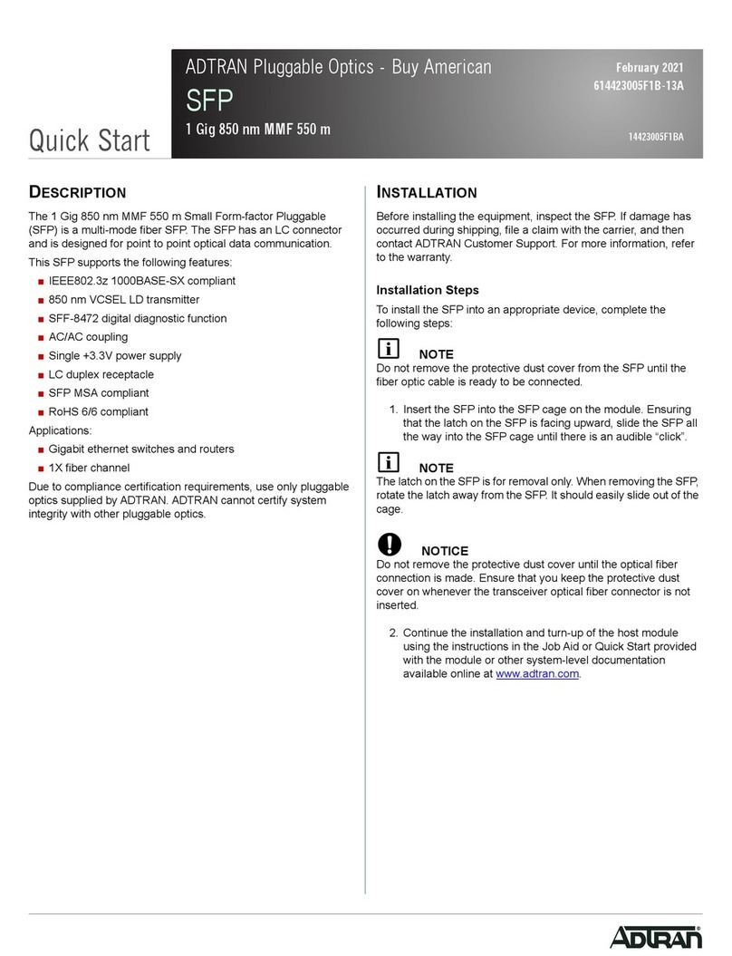
ADTRAN SFP User manual

ADTRAN

ADTRAN SFP User manual

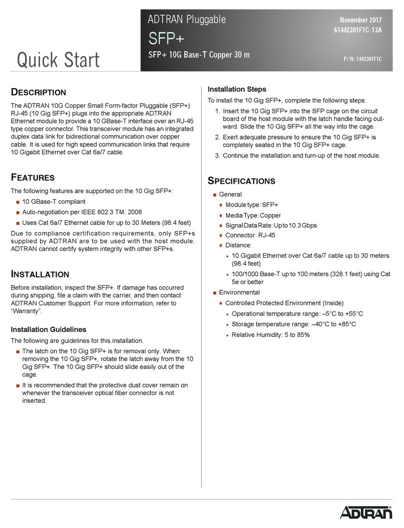
ADTRAN SFP+ 10G User manual

ADTRAN

ADTRAN SFP+ 10G User manual

ADTRAN E1 User manual

ADTRAN

ADTRAN E1 User manual

ADTRAN 1200222L1 User manual

ADTRAN

ADTRAN 1200222L1 User manual

ADTRAN SFP User manual

ADTRAN

ADTRAN SFP User manual

ADTRAN Total Access 1500 Instruction Manual

ADTRAN

ADTRAN Total Access 1500 Instruction Manual

ADTRAN Job Aid+ 1442940G1 User manual

ADTRAN

ADTRAN Job Aid+ 1442940G1 User manual

ADTRAN Total Access 300 Series Product manual

ADTRAN

ADTRAN Total Access 300 Series Product manual

ADTRAN U-BR1TE Instruction Manual

ADTRAN

ADTRAN U-BR1TE Instruction Manual

ADTRAN ATLAS 800 Series Module QUAD E1 User manual

ADTRAN

ADTRAN ATLAS 800 Series Module QUAD E1 User manual

ADTRAN IMUX-56 User manual

ADTRAN

ADTRAN IMUX-56 User manual

ADTRAN SFP GPON ONU User manual

ADTRAN

ADTRAN SFP GPON ONU User manual

ADTRAN 1442442F1 User manual

ADTRAN

ADTRAN 1442442F1 User manual

ADTRAN Modem-16 Module User manual

ADTRAN

ADTRAN Modem-16 Module User manual

ADTRAN Job Aid+ 1442910G1 User manual

ADTRAN

ADTRAN Job Aid+ 1442910G1 User manual

ADTRAN Job Aid+ 1442981G8C User manual

ADTRAN

ADTRAN Job Aid+ 1442981G8C User manual

ADTRAN SFP User manual

ADTRAN

ADTRAN SFP User manual

ADTRAN Job Aid+ 1442910G2 User manual

ADTRAN

ADTRAN Job Aid+ 1442910G2 User manual

ADTRAN GPON D OLT User manual

ADTRAN

ADTRAN GPON D OLT User manual

ADTRAN Total Access Quad BNC Instruction Manual

ADTRAN

ADTRAN Total Access Quad BNC Instruction Manual

ADTRAN Job Aid+ 1442704PG2 User manual

ADTRAN

ADTRAN Job Aid+ 1442704PG2 User manual

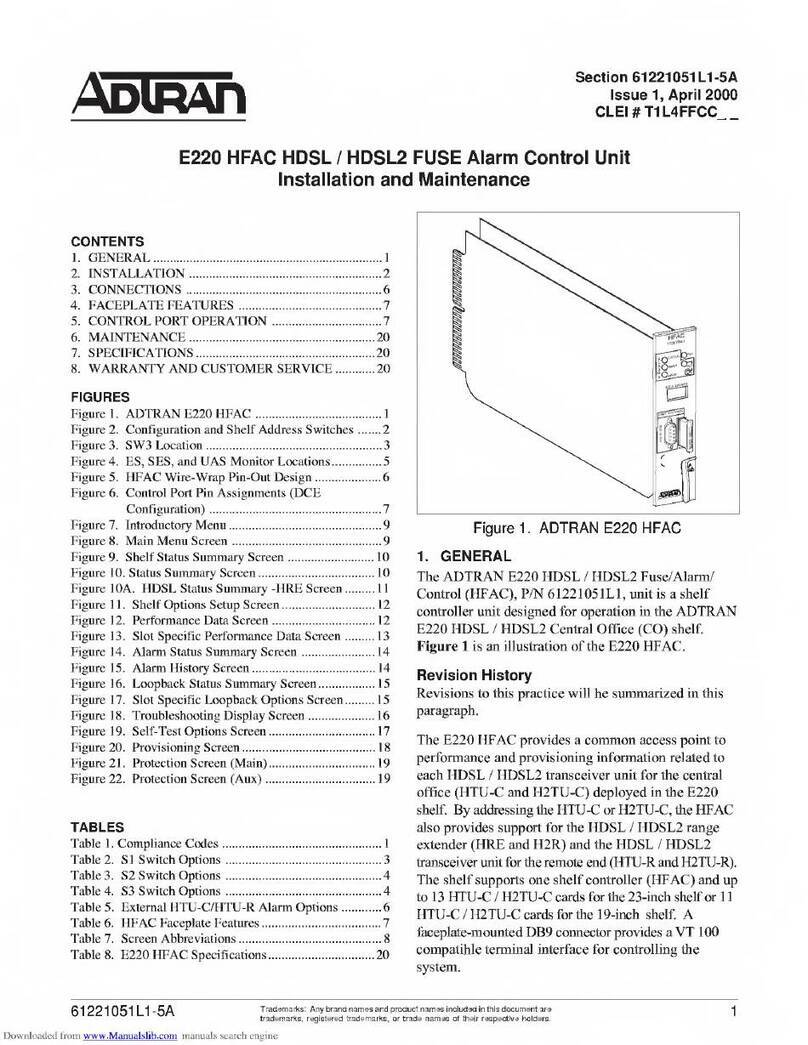
ADTRAN E220 HFAC HDSL Product manual

ADTRAN

ADTRAN E220 HFAC HDSL Product manual

ADTRAN Job Aid+ 1442804G1 User manual

ADTRAN

ADTRAN Job Aid+ 1442804G1 User manual

ADTRAN Octal BRI/U User manual

ADTRAN

ADTRAN Octal BRI/U User manual

Popular Control Unit manuals by other brands

Vintage Air 46115-VUH manual

Vintage Air

Vintage Air 46115-VUH manual

Quectel EP06 Hardware design

Quectel

Quectel EP06 Hardware design

Eaton 11 Series Installation and start-up guidelines

Eaton

Eaton 11 Series Installation and start-up guidelines

HORNE H-2501 Installation, operating,  & maintenance instructions

HORNE

HORNE H-2501 Installation, operating, & maintenance instructions

Texas Instruments DAC5674 EVM user guide

Texas Instruments

Texas Instruments DAC5674 EVM user guide

LOVATO ELECTRIC EXP10 14 instruction manual

LOVATO ELECTRIC

LOVATO ELECTRIC EXP10 14 instruction manual

Tube-Town TT PoS100 manual

Tube-Town

Tube-Town TT PoS100 manual

Cattron Remtron 411 user manual

Cattron

Cattron Remtron 411 user manual

morse 310 Series Operator's manual

morse

morse 310 Series Operator's manual

Siemens SIMOTION D410 manual

Siemens

Siemens SIMOTION D410 manual

US drives AC Regen instruction manual

US drives

US drives AC Regen instruction manual

Huawei G530 V2 White paper

Huawei

Huawei G530 V2 White paper

Minebea Intec Combics YDO07-X installation instructions

Minebea Intec

Minebea Intec Combics YDO07-X installation instructions

CKD CVE2 Series Safety

CKD

CKD CVE2 Series Safety

Ropam elektronik MGSM 5.0 Installation and operating manual

Ropam elektronik

Ropam elektronik MGSM 5.0 Installation and operating manual

Leviton 73A00-3ZB Installation instructions and user guide

Leviton

Leviton 73A00-3ZB Installation instructions and user guide

Velleman VMA501 user manual

Velleman

Velleman VMA501 user manual

NBB TM2400A user manual

NBB

NBB TM2400A user manual

manuals.online logo
manuals.online logoBrands
  • About & Mission
  • Contact us
  • Privacy Policy
  • Terms and Conditions

Copyright 2025 Manuals.Online. All Rights Reserved.