PIAGGIO Vespa Commercial Guide

['
"
()
)
-~
-'-~--"--'-"'--',~=.- "'1," ..., -- ..~..- ~~ ~ ~ ~ ~'-C ~ ",<1 '"
!
HWd. ~"., i
j
I
%..,J
I
SERVICE
STATION MANUAL
,
, I
"',",
,
1
1
.
~o.;.~- -~~- -- ...~~~ ~

~- " ,~- ..- ~~.
,<
'. FOREWORD
This Manual will serve as a complement to the booklet ({ Operation and Maintenance» for Authorised
Vespa Servit~ Stations and contains the following chapters: (,
.<
- Fault finding and remedies
Tooling necessary for normal servicing operations
Illustrations and instructions for stripping down, overhauls and assembly.
- Assel11bly play of main organs.
"",
~
J;
~"
it'
***
Please note that for correct and regular functioning of the vehicle it is indispensable that genuine
Piaggio spare parts be used. (
2.

)
)
=--
Ir'
'1\'
t
~
\
~;~-. J ~
~~~;.i ~. "10,
"';\
-4'
,
-,
..r'
"I
- -

Tips on fault finding and elimination
thereof to:
Engine
Transmission
Electrical equipment.
ji
Braking system
Controls, steering and suspension.
List of tools for:
Norma I use.
For inspection and special operations
Stripping down
Engine
Wheel brackets
Differential
Steering
Cable harness.
Cabin windows
4.
INDEX
. Page
)}
. Page 19
)} 24
»26
»27
)} 28
)} 28
Assembly play between
Con-rod., crankshaft.
Cylinder and piston.
Piston and wrist pin.
Con-rod, wrist pin
Piston rings
Gear box packing washers.
Hydraulic brake cylinder.
Rear wheel cylinder and piston.
Bush and liner of wheel brackets
16
Overhauls
Rotor magnetizing operation
Flywheel magneto test.
Gear change (sector lever and cable)
Clutch
Cush gear.
Bearing bushes of drive shaft.
Substitution of main bearing bushes.
. Page 6
)} 7
)} 7
)} 7
)} 8
.Page 29
)} 30 ()
)} 31
)} 31
)} 32
)} 33
)} 34
»34
» 35
. Page 36
)} 37
)) 38
»39 )
)} 40
» 41
)} 42

Tips on fault finding, functional irregularities and their
elimination
J
j
~
~
(.
Tooling for stripping down, overhauls, and assembly.
Stripping down
Assembly play
Overhauls to main groups.
Reassembly
. 5
~~ //
Substitution of small end bush . Page 43 Re-assembly
Substitution of wheel bracket bush,
liner and half shaft central support »46 Engine .Page 67
Inspection of rectifier. »48 Engine timrng . » 72
Electric starter motor (with description Differential »73
and illustration of the group) . » 50 Wheel bracket » 74
(Carburettor (description and tuning) »53 Steering column 75
»
Engine tests »55 Cabin windows 76
»
Road consumption test »56 Application of starter motor
Hydraulic brake 56 })' 77
»
Dampers »61 Starter lever assy . »78
Steering colum cover. »64 Application of tip-up platform. :) 79
Painting »65 Final adjustments before use. :> 80
INDEX OF CHAPTERS
.Page 6
» 11
»18
»29
» 36
»66

TIPS ON FAULT FINDING, FUNCTIONAL IRREGULARITIES
AND THEIR ELIMINATION
.~.~.
1. . Engine
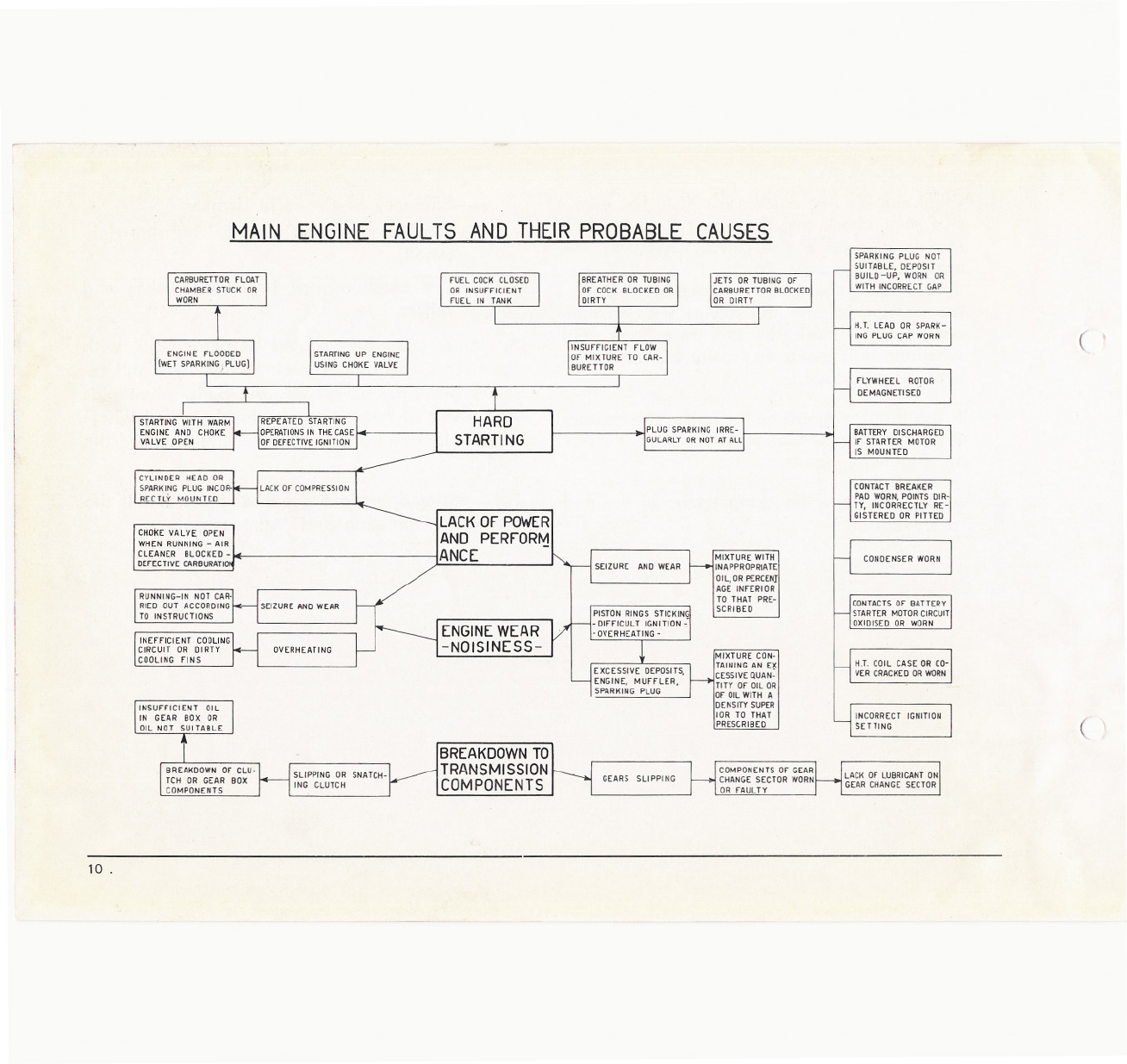
a) On page 10 is a summary of the engine faults
- most commonly verified during operation: ie,
ignition, fuel feed, carburation and lubrication.
For a normal adjustment or registration pro-
ceed according to the following instructions:
- In the case of poor performance, low com-
pression and pressure losses, check that the
engine groups in question are well secured
in position.
- On changing sparking plugs ensure that
the type prescribed in the booklet « Ope-
ration and Maintenance» are used. The
spark gap between the electrodes should
always be set at 0.6 mm (0."023).
- The gap between contact breaker points
should always come between the limits of
0.4 and 0.5 mm (0".015 and 0".019).
Spark advance: For for mods AC 1 and
AC 2; 28° :t: 1° for Mod. AC 3 25° :t: 1°.
- Groups clutch, gear change, should be ac-
curately checked for play with respect to
their relative cables (see pages 38 -;- 39
and control levers. In the case of clutch
slipping, check springs and plates and for
the gear box, control the parts comprising
the transmission in correspondence to the
selector quadrant.
r)
b) On stripping down or overhauling engine
groups, always use new split pins and gaskets
on re-assembly.
c) In the case where faults are verified which do
not enter under those indicated on the chart
at pag. 10, eg: abnormal engine noises, brea-
kages or premature wear to moving parts etc.)
it is necessary to localize the fault and substi-
tute or overhaul the part according to the con-
ditions prevailing: please note that the as-
sembly play of the main engine components
(piston-cylinder, piston rings etc.) should cor-
respond to those indicated on the table from
page 29 onwards.
)
6.

2. . Transmission
(
a) When engine and gear box are functioning re-
gularly and the vehicle will not start, or runs
irregularly, check the chain and relative organs,
differential, half shaft and proceed according
to the conditions prevailing.
b) To avoid noisy functioning and eventual break-
down to the transmission components, check
for lack of oil in the differential, wheel brackets
and that the driving chains are not excessively
slack or tight (adjust tension).
3. - Electricalequipment
(
Eventual inefficiencies to the ignition, or to lighting
equipment can be attributed to the generator, cir-
cuit connections or to the electrical equipment it-
self.
To eliminate the fault, carry out procedure indi-
cated on the following control Is:
a) If the starter motor is installed, in the case of
battery inefficiences caused by irregularities or
breakages in the charging circuit, check fly-
wheel magneto and rectifier.
For starter motor, see page 50.
Recharge the battery according to the infor-
mation given on the apposite instruction sheet.
b) On vehicles with normal starting unit check
flywheel magneto, magnetization and both e-
lectrical and mechanical timing. See pag. 37.
c) Check the electrical wiring for breakages to
the insulation; for battery cables carefully
check for corrosion or oxidation at the ter-
minals.
d) Check that terminals are not loose.
e) Inspect bulbs and ensure that they are in per-
fect contact with their relative sockets.
f ) Check connections, contacts to switch units and
fuses. ,~i
g) Check H. T. coil housing and terminal plates
for breakages.
4. - Braking system
a) Hydraulic brake
In the case of inefficient braking (or excessive
free pedal stroke) check:
.7

-Oil in the brake cylinder (for the type of
oil to use, see booklet «Operation and
Maintenance») iplease note that mineral
or similar type oils should not be used in-
somuch as they will eventually damage the
rubber valves and packings. Check for oil
losses at hydraulic brake cylinder. Where
the hydraulic oil circuit is found to have
inclusions of air bubbles, bleed off until
completely eliminated.
The play between brake jaws and drums
and if necessary adjust by means of the
apposite devices acting on the pedal and
brake jaws.
- Packing and valves of the hydraulic brake
cylinder and those on the wheel cylinders
and ensure that they are assembled correc-
tly (see from page 56 onwards).
N. B.
- In the case where normal adjustments are
not sufficient in eliminating the fault inspect
both the brake jaws and drums: if exces-
sive wear or scratching is noted, carry out
the necessary substitutions.
If the brake linings are impregnated with
oil, wash in gasoline and blow dry.
- If the hydraulic brake pedal is excessively
stiff, strip down and lubricate.
- After having carried out the necessary over-
hauls, repairs and adjustment to the braking
system, check braking efficiency of the
vehicle under normal running conditions.
(,
b) Mechanical brakes
- In the case of excessive free stroke of the le-
vers, adjust the registration screws placed at
the cable extremities.
- If the brake cables are rusted, lubricate or
change.
5) Controls steering and suspension
a) So as to avoid stiffness or rusting of the con-
trols, carry out the prescribed instructions on
lubrication (see booklet «Operation and Main-
tenance » ) .
(
8.
--~

,)
)
b) When the steering column is stiff or has exces-
sive play, check that the upper threaded ball
race is blocked at the correct pressure; see
instructions at page 76.
If on blocking the above mentioned component,
the steering column still rotates with an une-
ven motion, check the ball race track and
substitute if it has been locally worn and the
bearings embedded.
c) If the front suspension is noisy, (substitute
worn or faulty components accordingly) check
the following points.
- The spring, if knocking occurs at the end
of its run.
- Efficiency of the front damper.
That the nuts on the wheel hub are tigh-
tened.
- The conditions of bearings, bushes and
rollers.
A similar procedure should be carried out with
the rear suspension, (check torsion bars and re-
lative bearings, rubber damper pads, pivot pins
and plates of friction shock absorbers and wheel
bracket bronze bushes) after having localized the
fault.
For greasing operations, see those prescribed in the
booklet «Operation and Maintenance».
. 9

MAIN ENGINEFAULTSANDTHEIRPROBABLECAUSES
STARTING WITH WARM
ENGINE AND CHOKE
VALVE OPEN
CYUNDER HEAD OR I
SPARK ING PLUG INCOR,
RECfLY MOUNHD
RUNNING-IN NOT CAR'
I
RIED OUT ACCORDING
TO INSTRUCTIONS
INEFFICIENT COOLING
CIRCUIT OR DIRTY
CDOUNG fiNS OVERHEATING
SUPPING OR SNATCH-
ING CLUTCH
STARTINGUP ENGINE
USINGCHOKEVALVE
PLUG SPARKINGIRRE-
GULARLYORNOTATAll
LACKOFPOWER
AND PERFORt-1
ANCE SEIZURE AND WEAR MIXTUREWITH
INAPPROPRIATE
I
OIL,DRPERCENJ
AGE INfERIOR
TO THAT PRE-
SCRIBED
SPARKING PLUG NOT
SUITABLE, DEPOSIT
BUILD-UP, WORN OR
WITH INCORRECTGAP
H.T. LEAD OR SPARK-
ING PLUG CAPWORN (
ENGINEWEAR
-NOISINESS- i~~~~~EA~O~~
CESSIVEQUAN-
I
TITY Of OllaR
Of OILWITH A
DENSITYSUPER
lOR TO THAT
PRESCRIBED
fLYWHEEL ROTOR
oEMAGNETISED
BATTERYDISCHARGED
If STARTER MOTOR
IS MOUNTED
CONTACTBREAKER I
PAD WORN,POINTSOIR-
1
TY, INCORRECTLYRE-
GISTEREDOR PITTED
CONDENSERWORN
CONTACTSOf BATTERY
STARTERMOTORCIRCUIT
OXlolSEo OR wORN
H.T. COIL CASE ORCO-
VERCRACKEDORWORN
INCORRECTIGNITION
SETTING (
BREAKDOWNTO
TRANSMISSION
COMPONENTS GEARS SUPPING COMPONENTS Of GEAR
CHANGE SECTOR WORN
OR fAULTY
LACK Of LUBRICANT ON
GEAR CHANGE SECTOR
10 .

LISTOF TOOLS FOR STRIPPING DOWN, OVERHAULING AND RE-ASSEMBLINGTHE VEHICLE
Pari. No. Old 1001 slill
utilizable DESCRIPTION IIluslrated
a I page NOTES
)
a) - The tools illustrated in this Manual are valid for all normal operations of stripping down, as-
sembling and overhauling.
5479/A
7259/R
8002/RI
10394/0 I!
)
15362/C
15363/C
15364/C
T.16160/C
T.16161/C
T.19559/C
260222
381500/7
381504
381505
381505/7
381510/7
400345
713019/5
716050
6488/A
8290/R
4938/ A I
5115/A \
T.12380/C
381500/8
381505/8
381510/8
Hand press
Damper test bench
Engine test bench
63
62
55
Flywheel mag. test bench 37
Gauge
Tool setting gauge
Tool setting gauge
Wrist pin gauge
Wrist pin gauge (1 st o/s.).
Tool for crankshaft alignment
Milling cutter for chuck 0018801
Reamer for con-rod small end.
Piston reamer 1st o/s (Roughing cut)
Piston reamer 1st o/s (finishing cut)
Reamer for con-rod small end 1st o/s.
Can - rod small end reamer
Reamer
Drill for main bearing bushes on crankcase
-.
-
~--
45
45
70
47
44
45
45
44.45
44
-
42
42
.11
-- -

Part. No.
784043
784424
845133
781103
0013964
T .00 14499
0014566
0015413
T.0015713
T.0016029
T.0016561
T.0017104
T.0017202
0017549
01>17780
0017808
0017820
0017831
0017843
0017898
Old tool slill
utilizable
0015600
0015713
DESCRIPTION
Turning tool for bush
Square shank turning tool
4 insert milling cutters
Tool for locking flywheel
Bearing extractor
Wrench for threaded ring of upper steering column
bearing
jig for overhauling cush gear
Bearing extractor for drive shaft
jig for assembling lower race of steering column
bottom bearing
jig for removing bottom race of lower steering
column bearing
Pliers for removing circlips
Differential support base
Wrench for threaded ring
Drill chuck for substituting main bearing bushes
Oil seal protective sheath for assy. crankshaft
Punch for wrist pin extraction
Crankshaft protective sheath for assy. crankcase
(flywheel side).
Punch for removing oil seals from crankcase halves
Punch for mounting front wheel bearing housing
bush
Illustrated
at page
42
42
-
-
19
20.24.26.27
24.27-74.75
40
21
75
27
19-2.5-74
26
63
42
70
19
70
23
7.5
NOTES
( .~
(
12.

)
)
.13
Old tool still Illustrated NOTESPart. No. utilizable DESCRIPTION at page
0018094 Feeler gauge for checking axial play of bearings 33
on drive shaft
T.0018119 T.OO1Slll Half-shaft extractor 24
T.0018128 Punch for drive shaft bearings 67.74
0018204 Sheath for assy of rubber washer 63
0018205 Sheath for assy of felt washer 63
0018219 Wrench for fixing front damper to steering column 27
0018497 Extractor for upper and lower pivot pins 24
0018499 Tool for aligning wheel bracket supports 47
T.0018501 Wrench for rear wheel shaft 25
0018801 Chuck for reaming wheel bracket bush -
T.OO18879 Tool for assy of wheel bracket bush 46
T.0018916 Work holder for substitution of main bearing bu.. 42
shes
T.0019353 Box wrench for clutch securing nut 19
T.0019354 Box wrench for clutch securing nut 19
T.0019859 Support base for crankcase (flywheel side) 69
0019978 Heater (220 V-50 Hz or 260 V-50 Hz) 69.73
T.0019982 Wrench for main body of starter 69
T.0020096 Jig for assy of bearing on half-shaft support 74
T.0020097 Punch for assy. oil seal on half-haft support 74
T.0020128 Double hook-wrench for blocking clutch 19
T.0020168 Punch for assy starter group 69
,T.0020185 Supplementary fuel tank for consumption tests 56
T.0020200 Extractor for wheel bracket bearing 24

Part. No.
T.0020224
0020261
T.0020322
T.0020781
T.0020811
T.0020824
Old 1001 still
utilizable
T.0018218
T.0015046
T.0020826
T.0020827
1.0020828
T.0020837a)
1.0020840 I\T.0014677
I0013767
1.0020841 IT.001 8130
T.0020865
T.0020866
T.0020867
T.0020868
T.0020872
T.0020897
T.0021 009
T.0021 071
T .0021265
T.0020225
T.0014924
T.0016310
DESCRIPTION
jig for assy. oil seal
jig for assy. oil seal to planetary gear housing
jig for assy. and stripping down clutch
Punch
Tool for actioning piston when excluding air
Base for application of tools on assy. of rubber
buffers and sleeve
Tool for assy of buffer and sleeve on damper body
Tool for assy. of buffer and tube on stem support
Tool for assy. valve group to cylinder
Drive shaft extractor
Wrench for threaded ring securing bearing to wheel
bracket and crankcase halves
jig for stripping down front wheel axle and assy.
of bearing
Tool for machining flat plane
Milling cutter and inserts
Reaming jig
Reaming chuck
jig for reaming dowel hole
Tool for reaming wrist pin housing
Bush to be used in conjunction with the punch
T.0018128
Punch for assy. oil seal to crankcase halves
Fan extractor
Illuslraled
aI pag e
41 -74
73
39
67-68
63
63
63
63
63
--
21.2..6~.74
27
-
-
--
-
-
45
74
67
19
NOTES
)
~) Valid for mods
AC 1 only. From
mods AC 2 on
wards use a piece
of standard stock.
, )
14 .

--
)
)
. 15
Old tool still DESCRIPTION Illustrated NOTESParI. No. utilizable at page
1.0021272 T.00 16303 Extractor for wheel bracket oil seals 24
T.0021280 0017971 Tool for assy. conical spline on gear change sector 38
T.0021330 Tool for assy. steering column bearings 75
T.0021334 Tool for protecting packing on assy of wheel bra- 74
ckets to chassis
0021346 Wrench for assy and dismantling starter motor -
0021350 Tool for assy. of rubber seal strip to cabin 76
I
T.0021436 Punch for assy. oil seal 73
T.0021467 T.0018182 Extractor for crankshaft and differential bearings 21-26
T.0022480 Punch for extracting drive shaft bearing bush 41
T.0023278 Apparatus for engine timing 72
T.0023465 T.0016205 Graduated disc for engine timing 72
0023638 Pliers for removing circlips 22.26
j LOO.7138
Tool for separating crankcase halves and extraction 20
T.0023745 T.0017642 of crankshaft
T.0020877
T.0023853 Indexing device for engine timing 72
T.0025095 !4105/A Engine support 19
T.0013782
T.0025125 T.0021084 Wrench for threaded ring blocking brake cylinder 58
T.0025127 0017802 Wedge 20.70
T.0026363 Punch for assy. oil seal on drive shaft 68
! LOO22532
T.0027159 T.0021175 Tool for centering con-rod 43.44
T.0016334

~~--
Pari. No.
T.OO27160
T.0027501
~-- .~.- --
Old tool still
utilizable
j
T.0024601
T.0021257
T.0016338
\0013589
/T.0022547
-,
DESCRIPTION Illustraled
at page NOTES
Tool for substituting small end bush 43.44 I
Magnetizer 36 1)
062 -0,026 (p6)
- 0,045
066 +: g046 (H8)
0 68.5 +:6046(H8)
Double ended plug gauge
b) - Other tools for inspection and special operations which are not however indispensable for
normal opns.
13768/C
T.0013460
T.0014208
15104/C
15120/C
T.15648/C
T.0021472
T.0023223
T.0023234
T.0024448
6698/ A Vehicle mobile support
Base for assy. of coiIs to stator
Tool for crankshaft assy. (1st opn,)
Tool for crankshaft assy. (2nd opn.)
Base for steering column inspection gauge
Gauge for steering column
Profile gauge for chassis
Tool for stripping down crankshaft
Tool for overhaul and inspection of clutch
Tool for checking static torque on clutch
Tool for removing crankpin
-
-
-
-
-
-
-- 1 )
--.
--..
-
-
16 .

Part. No.
)
T .0026482
381509
381510
0016741
0017004 b)
T.0021413C)
T.0026471
T .0026482
550804
550805
)
Old tool still
utilizable
0015284
0014000
0016538
0017102
0018496
0018878
T .00 1 8880
T.0018881
T.0018883
T .00 19273
T .00 15283
T.0015284
DESCRIPTION
Fan balancing shaft
Piston reamer 2nd o/s (Roughing cut)
Piston reamer 2nd o/s (finishing cut)
Tool for securing steering column to vice jaws
Tool for cleaning exhaust pipe
Feeler gauge for contact breaker and spark gap
Special screwdriver
Extractor for rear wheel bushes
Pliers for rear brake, return spring
Plunger for bleeding opn.
Tool securing cylinder to vice
Tool for securing wheel cylinder to vice
Tool for assy hydraulic cylinder valves
Tool for assy and dismantling selector spider
Wrench for threaded ring on security lock
Mandrel for turning opn.
Balancing shaft
Punch
Punch
065 :;g,19 (H11) Double ended plug gauge
Illustrated
at page NOTES
-
-
-
-- b) Screwdriver
with cut -out for
assy. of threaded
ring nut securing
gear change and
brake levers to
handlebars; can be
made from a stan-
dard screwdriver.
--
-
-
--
-
-
-
-
-
-
-
-
-c) Valid only for
mod. AC 1.
-
-
. 17

STRIPPING DOWN
NOTE:
On the following pages are illustrated the main stripping down operations for
ling or' apparatus is necessary. Simple operations which can be carried out using
screwdriver, wrenches, pliers etc., are not indicated.
We consider it advisable that the relative «Spare Parts List» be
operations In.s9much as it indicates in illustrated form the various
,,-,i."
_'0'
,'W';:;.)'
which special too-
standard tools, ego
consulted before carrying out these
exploded group components.
18 .
l~_-
( 1
( I

---- -~
STRIPPINGDOWN
Engine components
)1. 00.19354
1.0020128
/
B
c
~
A
A): Wrist
N. B. pin, piston and clutch securing nut.
- For removing the circlip standard long nosed pliers
can be used or the type T. 0017104.
Use the same wrenches as indicated above for blo-
cking clutch retainer nut for clutches without crown
wheel (for vehicles without starter motor).
Fig. 1
B): Flywheel nut (use the tool T. 0021265 in cases of difficulty).
J
C): Introduce the clamps into rotor cut-out and tighten towards
the centre until the cam collar is surpassed; block the screws
then extract the flywheel by acting on the the' threaded pin
clamps with 19 mm wrench.
. 19

-- -
STRIPPING DOWN
Crankcase - Crankshaft
tf.
T.0025127
/
~.
,~
.,;;.,
~'\
;"~'
..
A
s'
Fig. 2
A): Seperating crankcase halves: Insert the wedge 1. 0025127
so as to avoid deformation of crankshaft.
N. B. - Suitably dispose a drip pan. to collect the oil
which will flow out.
c(I
()
B
T.0014499
\
B): Crankshaft.
C): Bearings if they remain on crankshaft.
20 .
Table of contents
Other PIAGGIO Utility Vehicle manuals