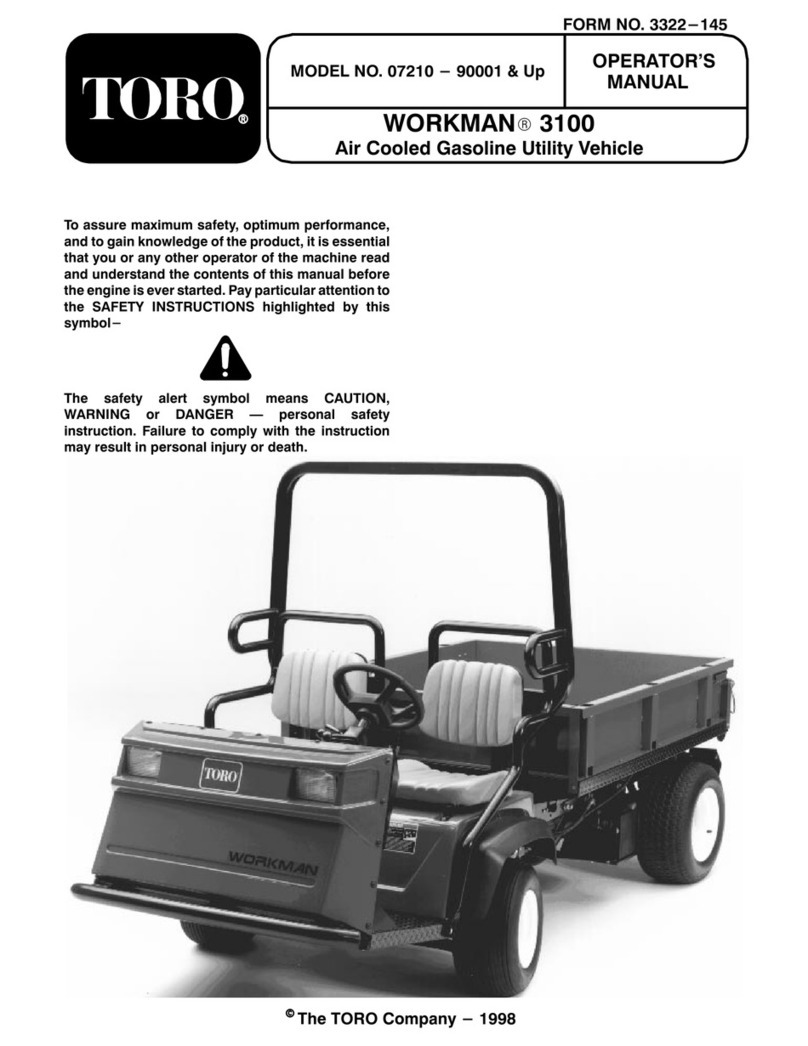
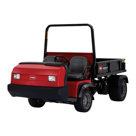
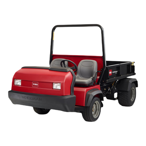
Toro Workman MDX User manual

Form No. 3463-619 Rev A
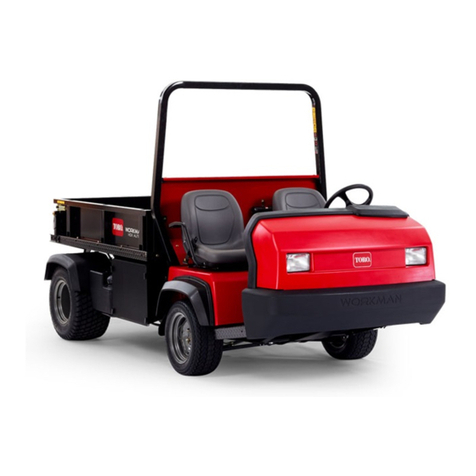
W orkman
®
MDX Utility V ehicle
Model No. 07235 —Serial No. 414800200 and Up
Model No. 07235TC —Serial No. 414849661 and Up
Register at www .T oro.com.
Original Instructions (EN)
*3463-619*

This product complies with all relevant European
directives; for details, please see the separate product
specic Declaration of Conformity (DOC) sheet.
It is a violation of California Public Resource Code
Section 4442 or 4443 to use or operate the engine on
any forest-covered, brush-covered, or grass-covered
land unless the engine is equipped with a spark
arrester , as dened in Section 4442, maintained in
ef fective working order or the engine is constructed,
equipped, and maintained for the prevention of re.
The enclosed engine owner's manual is supplied
for information regarding the US Environmental
Protection Agency (EP A) and the California Emission
Control Regulation of emission systems, maintenance,
and warranty . Replacements may be ordered through
the engine manufacturer .
W ARNING
CALIFORNIA
Proposition 65 W arning
The engine exhaust from this product
contains chemicals known to the State of
California to cause cancer , birth defects,
or other reproductive harm.
Battery posts, terminals, and related
accessories contain lead and lead
compounds, chemicals known to
the State of California to cause
cancer and reproductive harm. W ash
hands after handling.
© 2023—The T oro® Company
81 1 1 L yndale A venue South
Bloomington, MN 55420
2
Contact us at www .T oro.com.
Printed in the USA
All Rights Reserved

Introduction
This utility vehicle is intended to be primarily used
of f-highway to transport people and material loads.
Using this product for purposes other than its intended
use could prove dangerous to you and bystanders.
Read this information carefully to learn how to operate
and maintain your product properly and to avoid
injury and product damage. Y ou are responsible for
operating the product properly and safely .
V isit www .T oro.com for product safety and operation
training materials, accessory information, help nding
a dealer , or to register your product.
Whenever you need service, genuine T oro parts, or
additional information, contact an Authorized Service
Dealer or T oro Customer Service and have the model
and serial numbers of your product ready . Figure 1
identies the location of the model and serial numbers
on the product. W rite the numbers in the space
provided.
Important: W ith your mobile device, you can
scan the QR code on the serial number decal (if
equipped) to access warranty , parts, and other
product information.
g312723
Figure 1
1. Model and serial number location
Model No.
Serial No.
This manual uses 2 words to highlight information.
Important calls attention to special mechanical
information and Note emphasizes general information
worthy of special attention.
The safety-alert symbol ( Figure 2 ) appears both in
this manual and on the machine to identify important
safety messages that you must follow to avoid
accidents. This symbol will appear with the word
Danger ,W arning , or Caution .
•Danger indicates an imminently hazardous
situation which, if not avoided, will result in death
or serious injury .
•W arning indicates a potentially hazardous
situation which, if not avoided, could result in
death or serious injury .
•Caution indicates a potentially hazardous situation
which, if not avoided, may result in minor or
moderate injury .
g000502
Figure 2
Safety-alert symbol
3

Contents
Safety . . . . . . . . . . . . . . . . . . . . . . . . . . . . . . . . . . . . . . . . . . . . . . . . . . . . . . . . . . . . . . . . . . . . . . . 5
General Safety . . . . . . . . . . . . . . . . . . . . . . . . . . . . . . . . . . . . . . . . . . . . . . . . . . . 5
Safety and Instructional Decals . . . . . . . . . . . . . . . . . . . . . . . . . . 6
Setup . . . . . . . . . . . . . . . . . . . . . . . . . . . . . . . . . . . . . . . . . . . . . . . . . . . . . . . . . . . . . . . . . . . . . . . . 9
1 Installing the Steering Wheel . . . . . . . . . . . . . . . . . . . . . . . . . . . . 9
2 Connecting the Battery . . . . . . . . . . . . . . . . . . . . . . . . . . . . . . . . . . . . 9
3 Checking the Fluid Levels and T ire
Pressure . . . . . . . . . . . . . . . . . . . . . . . . . . . . . . . . . . . . . . . . . . . . . . . . . . . . . . . 10
4 Burnishing the Brakes . . . . . . . . . . . . . . . . . . . . . . . . . . . . . . . . . . . . 10
5 Reading the Manual and V iewing the
Setup Material . . . . . . . . . . . . . . . . . . . . . . . . . . . . . . . . . . . . . . . . . . . . . . . . 1 1
Product Overview . . . . . . . . . . . . . . . . . . . . . . . . . . . . . . . . . . . . . . . . . . . . . . . . . . . 12
Controls . . . . . . . . . . . . . . . . . . . . . . . . . . . . . . . . . . . . . . . . . . . . . . . . . . . . . . . . . . . 13
Specications . . . . . . . . . . . . . . . . . . . . . . . . . . . . . . . . . . . . . . . . . . . . . . . . . . 16
Attachments/Accessories . . . . . . . . . . . . . . . . . . . . . . . . . . . . . . . . . 16
Before Operation . . . . . . . . . . . . . . . . . . . . . . . . . . . . . . . . . . . . . . . . . . . . . . . . . 17
Before Operation Safety . . . . . . . . . . . . . . . . . . . . . . . . . . . . . . . . . . . 17
Performing Daily Maintenance . . . . . . . . . . . . . . . . . . . . . . . . . . 17
Checking the T ire Pressure . . . . . . . . . . . . . . . . . . . . . . . . . . . . . . . 17
Adding Fuel . . . . . . . . . . . . . . . . . . . . . . . . . . . . . . . . . . . . . . . . . . . . . . . . . . . . . . 18
Breaking in a New Machine . . . . . . . . . . . . . . . . . . . . . . . . . . . . . . 18
During Operation . . . . . . . . . . . . . . . . . . . . . . . . . . . . . . . . . . . . . . . . . . . . . . . . . 19
During Operation Safety . . . . . . . . . . . . . . . . . . . . . . . . . . . . . . . . . . . 19
Operating the Cargo Bed . . . . . . . . . . . . . . . . . . . . . . . . . . . . . . . . . . 20
Starting the Engine . . . . . . . . . . . . . . . . . . . . . . . . . . . . . . . . . . . . . . . . . . . 22
Stopping the Machine . . . . . . . . . . . . . . . . . . . . . . . . . . . . . . . . . . . . . . . 22
Loading the Cargo Bed . . . . . . . . . . . . . . . . . . . . . . . . . . . . . . . . . . . . . 23
After Operation . . . . . . . . . . . . . . . . . . . . . . . . . . . . . . . . . . . . . . . . . . . . . . . . . . . . 24
After Operation Safety . . . . . . . . . . . . . . . . . . . . . . . . . . . . . . . . . . . . . . 24
Hauling the Machine . . . . . . . . . . . . . . . . . . . . . . . . . . . . . . . . . . . . . . . . . 24
T owing the Machine . . . . . . . . . . . . . . . . . . . . . . . . . . . . . . . . . . . . . . . . . . 25
T owing a T railer . . . . . . . . . . . . . . . . . . . . . . . . . . . . . . . . . . . . . . . . . . . . . . . . 25
Maintenance . . . . . . . . . . . . . . . . . . . . . . . . . . . . . . . . . . . . . . . . . . . . . . . . . . . . . . . . . . . 26
Maintenance Safety . . . . . . . . . . . . . . . . . . . . . . . . . . . . . . . . . . . . . . . . . . 26
Recommended Maintenance Schedule(s) . . . . . . . . . . . 26
Daily Maintenance Checklist . . . . . . . . . . . . . . . . . . . . . . . . . . . . . 28
Maintaining the Machine under Special
Operating Conditions . . . . . . . . . . . . . . . . . . . . . . . . . . . . . . . . . . . . 28
Pre-Maintenance Procedures . . . . . . . . . . . . . . . . . . . . . . . . . . . . . . 29
Preparing the Machine for Maintenance . . . . . . . . . . . . 29
Lifting the Machine . . . . . . . . . . . . . . . . . . . . . . . . . . . . . . . . . . . . . . . . . . . 29
Accessing the Hood . . . . . . . . . . . . . . . . . . . . . . . . . . . . . . . . . . . . . . . . . . 30
Lubrication . . . . . . . . . . . . . . . . . . . . . . . . . . . . . . . . . . . . . . . . . . . . . . . . . . . . . . . . . . 30
Greasing the Front Wheel Bearings . . . . . . . . . . . . . . . . . . 30
Engine Maintenance . . . . . . . . . . . . . . . . . . . . . . . . . . . . . . . . . . . . . . . . . . . 33
Engine Safety . . . . . . . . . . . . . . . . . . . . . . . . . . . . . . . . . . . . . . . . . . . . . . . . . . . 33
Servicing the Air Filter . . . . . . . . . . . . . . . . . . . . . . . . . . . . . . . . . . . . . . . 33
Servicing the Engine Oil . . . . . . . . . . . . . . . . . . . . . . . . . . . . . . . . . . . . 35
Servicing the Spark Plugs . . . . . . . . . . . . . . . . . . . . . . . . . . . . . . . . . 36
Adjusting the High/Low Idle . . . . . . . . . . . . . . . . . . . . . . . . . . . . . . 37
Fuel System Maintenance . . . . . . . . . . . . . . . . . . . . . . . . . . . . . . . . . . . 37
Inspecting Fuel Lines and Connections . . . . . . . . . . . . . 37
Replacing the Fuel Filter . . . . . . . . . . . . . . . . . . . . . . . . . . . . . . . . . . . 37
Servicing the Carbon Canister . . . . . . . . . . . . . . . . . . . . . . . . . . 38
Electrical System Maintenance . . . . . . . . . . . . . . . . . . . . . . . . . . . 42
Electrical System Safety . . . . . . . . . . . . . . . . . . . . . . . . . . . . . . . . . . . 42
Servicing the Battery . . . . . . . . . . . . . . . . . . . . . . . . . . . . . . . . . . . . . . . . . 42
Replacing the Fuses . . . . . . . . . . . . . . . . . . . . . . . . . . . . . . . . . . . . . . . . . 43
Maintaining the Headlights . . . . . . . . . . . . . . . . . . . . . . . . . . . . . . . 44
Drive System Maintenance . . . . . . . . . . . . . . . . . . . . . . . . . . . . . . . . . . 45
Maintaining the T ires . . . . . . . . . . . . . . . . . . . . . . . . . . . . . . . . . . . . . . . . 45
Inspecting the Steering and Suspension
Components . . . . . . . . . . . . . . . . . . . . . . . . . . . . . . . . . . . . . . . . . . . . . . . . . 45
Adjusting the Front Wheel Alignment . . . . . . . . . . . . . . . . 46
Checking the T ransaxle-Fluid Level . . . . . . . . . . . . . . . . . . 47
Changing the T ransaxle Fluid . . . . . . . . . . . . . . . . . . . . . . . . . . . 47
Checking and Adjusting Neutral . . . . . . . . . . . . . . . . . . . . . . . . 48
Maintaining the Primary Drive Clutch . . . . . . . . . . . . . . . . 48
Reducing the T op Speed . . . . . . . . . . . . . . . . . . . . . . . . . . . . . . . . . . . 49
Cooling System Maintenance . . . . . . . . . . . . . . . . . . . . . . . . . . . . . . 50
Cooling System Safety . . . . . . . . . . . . . . . . . . . . . . . . . . . . . . . . . . . . . 50
Cleaning the Engine-Cooling Areas . . . . . . . . . . . . . . . . . . 50
Brake Maintenance . . . . . . . . . . . . . . . . . . . . . . . . . . . . . . . . . . . . . . . . . . . . . 50
Inspecting the Brakes . . . . . . . . . . . . . . . . . . . . . . . . . . . . . . . . . . . . . . . 50
Adjusting the Parking-Brake Handle . . . . . . . . . . . . . . . . . 50
Adjusting the Brake Cables . . . . . . . . . . . . . . . . . . . . . . . . . . . . . . . 51
Checking the Brake-Fluid Level . . . . . . . . . . . . . . . . . . . . . . . . 52
Changing the Brake Fluid . . . . . . . . . . . . . . . . . . . . . . . . . . . . . . . . . 52
Belt Maintenance . . . . . . . . . . . . . . . . . . . . . . . . . . . . . . . . . . . . . . . . . . . . . . . . 53
Servicing the Drive Belt . . . . . . . . . . . . . . . . . . . . . . . . . . . . . . . . . . . . . 53
Adjusting the Starter-Generator Belt . . . . . . . . . . . . . . . . . 53
Chassis Maintenance . . . . . . . . . . . . . . . . . . . . . . . . . . . . . . . . . . . . . . . . . . . 54
Adjusting the Cargo-Bed Latches . . . . . . . . . . . . . . . . . . . . . 54
Cleaning . . . . . . . . . . . . . . . . . . . . . . . . . . . . . . . . . . . . . . . . . . . . . . . . . . . . . . . . . . . . . . 54
W ashing the Machine . . . . . . . . . . . . . . . . . . . . . . . . . . . . . . . . . . . . . . . 54
Storage . . . . . . . . . . . . . . . . . . . . . . . . . . . . . . . . . . . . . . . . . . . . . . . . . . . . . . . . . . . . . . . . . . . 55
Storage Safety . . . . . . . . . . . . . . . . . . . . . . . . . . . . . . . . . . . . . . . . . . . . . . . . . . 55
Storing the Machine . . . . . . . . . . . . . . . . . . . . . . . . . . . . . . . . . . . . . . . . . . 55
4
Safety
This machine has been designed in accordance with
the requirements of SAE J2258 (Nov 2016).
General Safety
This product is capable of causing personal injury .
Always follow all safety instructions to avoid serious
personal injury .
•Read and understand the contents of this
Operator ’ s Manual before you start the machine.
Ensure that everyone using this product knows
how to use it and understands the warnings.
•Use your full attention while operating the
machine. Do not engage in any activity that
causes distractions; otherwise, injury or property
damage may occur .
•Do not put your hands or feet near moving
components of the machine.
•Do not operate the machine without all guards
and other safety protective devices in place and
working on the machine.
•Keep bystanders and children out of the operating
area. Never allow children to operate the machine.
•Stop and shut of f the machine and remove the key
before servicing or fueling.
Improperly using or maintaining this machine can
result in injury . T o reduce the potential for injury ,
comply with these safety instructions and always
pay attention to the safety-alert symbol , which
means Caution, W arning, or Danger—personal safety
instruction. Failure to comply with these instructions
may result in personal injury or death.
5

Safety and Instructional Decals
Safety decals and instructions are easily visible to the operator and are located near any area
of potential danger . Replace any decal that is damaged or missing.
decal99-7345
99-7345
1. W arning—read the Operator's Manual .
2. W arning—do not touch the hot surface.
3. Entanglement hazard, belt—stay away from moving parts;
keep all guards in place.
4. Crushing hazard, cargo box—use the prop rod to support
the cargo bed.
decal99-7952
99-7952
1. Choke
3. Neutral
2. Reverse 4. Forward
decal1 15-2412
1 15-2412
1. W arning—read the Operator's Manual ; no storage.
decal1 15-7739
1 15-7739
1. Falling, crushing hazard—do not carry passengers.
decal136-1 164
136-1 164
1. Do not exceed a tongue
weight of 45 kg (100 lb).
2. Do not exceed a transport
load of 363 kg (800 lb).
6

decal145-2269
145-2269
1. Of f
3. T o start the engine, sit in the operator's seat, disengage the
parking brake, turn the key on, adjust the choke, and press
the accelerator pedal.
2. On 4. T o shut of f the engine, release the accelerator pedal, engage
the parking brake, turn the key of f, and remove the key .
decal147-8185
147-8185
1. USB plug
7

decal145-2277
145-2277
1. W arning—read the Operator ’ s Manual and receive training
before operating the machine.
5. Falling hazard; severing hazard of hand or foot—do not carry
passengers in the bed; do not carry a third passenger; do not
put your hands or feet outside the machine while operating.
2. W arning—wear hearing protection.
6. Collision hazard—do not operate the machine on public
streets, roads, or highways.
3. Fire hazard—shut of f the engine before refueling.
7. Falling hazard—do not allow children to operate the machine.
4. T ipping hazard—drive slowly on or across inclines; take turns
slowly; do not exceed speeds of 31 kph (19 mph); drive slowly
when hauling a load or when driving on uneven terrain.
decal145-2278
145-2278
1. Read the Operator's
Manual for fuse
information.
4. Headlights (10 A)
2. Bed lift (15 A)—optional kit 5. Machine fuse (10 A)
3. Horn/USB power point (20
A)
8

Setup
Loose Parts
Use the chart below to verify that all parts have been shipped.
Procedure Description
Qty .
Use
Steering wheel
1
Cover
11
W asher (1/2 inch)
1
Install the steering wheel (TC models
only).
2
No parts required
–
Connect the battery (TC models only).
3
No parts required
–
Check the uid levels and tire pressure.
4

No parts required
–
Burnish (break-in) the brakes.
Operator's Manual
1
Engine owner's manual 1
Registration card 1
Predelivery Inspection Form 1
Certicate of Quality
15
Key 2
Read the Operator's Manual and view
the setup material before operating the
machine.
Note: Determine the left and right sides of the machine from the normal operating position.
1
Installing the Steering
Wheel
TC Models Only
Parts needed for this procedure:
1
Steering wheel
1
Cover
1
W asher (1/2 inch)
Procedure
1. If the cover is installed, remove it from the hub
of the steering wheel ( Figure 3 ).
2. Remove the locknut (1/2 inch) from the steering
shaft ( Figure 3 ).
3. Slide the steering wheel and washer (1/2 inch)
onto the steering shaft ( Figure 3 ).
4. Secure the steering wheel to the shaft with the
locknut (1/2 inch) and tighten it to 27 to 34 N∙m
(20 to 25 ft-lb).
5. Install the cover on the steering wheel ( Figure 3 ).
g033840
Figure 3
1. Cover 4. Steering wheel
2. Locknut (1/2 inch) 5. Steering shaft
3. W asher (1/2 inch)
9

2
Connecting the Battery
TC Models Only
No Parts Required
Procedure
W ARNING
Incorrectly routing the battery cable could
damage the machine and cables, causing
sparks. Sparks can cause the battery gasses
to explode, resulting in personal injury .
• Always disconnect the negative battery
cable (black) before disconnecting the
positive battery cable (red).
• Always connect the positive battery cable
(red) rst.
1. Squeeze the battery cover to release the tabs
from the battery base ( Figure 4 ).
g228188
Figure 4
1. Battery cover
2. Remove the battery cover from the battery base
(Figure 4 ).
3. Connect the positive battery cable (red) to the
positive (+) terminal of the battery and secure
the cable with the bolts and nuts ( Figure 5 ).
g228187
Figure 5
1. Insulator boot (positive
battery cable)
3. Negative battery post
2. Negative battery cable
(black)
4. Slide the insulator boot over the positive
terminal.
Note: The insulator boot prevents a possible
short-to-ground from occurring.
5. Connect the negative battery cable (black) to the
negative (–) terminal of the battery and secure
the cable with the bolts and nuts.
6. Align the battery cover to the battery base
(Figure 4 ).
7. Squeeze the battery cover , align the tabs to
the battery base, and release the battery cover
(Figure 4 ).
3
Checking the Fluid Levels
and T ire Pressure
No Parts Required
Procedure
1. Check the engine-oil level before and after
you rst start the engine; refer to Checking the
Engine-Oil Level ( page 35 ) .
2. Check the brake-uid level before you rst start
the engine; refer to Checking the Brake-Fluid
Level ( page 52 ) .
3. Check the transaxle-uid level before you
rst start the engine; refer to Checking the
T ransaxle-Fluid Level ( page 47 ) .
4. Check the air pressure in the tires; refer to
Checking the T ire Pressure ( page 17 ) .
10

4
Burnishing the Brakes
No Parts Required
Procedure
T o ensure optimum performance of the brake system,
burnish (break-in) the brakes before use.
1. Bring the machine up to full speed, apply the
brakes to rapidly stop the machine without
locking up the tires.
2. Repeat this procedure 10 times, waiting 1 minute
between stops, to avoid overheating the brakes.
Important: This procedure is most effective
if the machine is loaded with 227 kg (500 lb).
5
Reading the Manual and
V iewing the Setup Material
Parts needed for this procedure:
1
Operator's Manual
1 Engine owner's manual
1 Registration card
1Predelivery Inspection Form
1
Certicate of Quality
2 Key
Procedure
•Read the Operator's Manual and the engine
owner's manual.
•Fill out the registration card.
•Complete the Predelivery Inspection Form .
•Review the Certicate of Quality .
1 1

Product Overview
g033215
Figure 6
1. Hood latch
3. Cargo bed 5. Gear-shift selector 7. Cargo-bed lever
2. Parking-brake lever 4. T owing tongue 6. Fuel-tank cap
12

Controls
Become familiar with all the controls before you start the engine and operate the machine.
Control Panel
g382793
Figure 7
1. Horn switch
6. USB power point
2. Light switch 7. Parking-brake lever
3. Hour meter 8. Accelerator pedal
4. Engine oil-pressure Light 9. Brake pedal
5. Key switch
Accelerator Pedal
Use the accelerator pedal ( Figure 7 ) to vary the
ground speed of the machine. Pressing down the
accelerator pedal starts the engine. Pressing the
pedal farther increases the ground speed. Releasing
the pedal slows the machine, and the engine shuts of f.
Note: The maximum forward speed is 26 km/h
(16 mph).
Brake Pedal
Use the brake pedal to stop or slow the machine
(Figure 7 ).
CAUTION
Operating a machine with worn or incorrectly
adjusted brakes can may result in personal
injury .
If the brake pedal travels to within 25 mm (1
inch) of the machine oor board, adjust or
repair the brakes.
Parking-Brake Lever
The parking-brake lever is located between the seats
(Figure 6 and Figure 7 ). Whenever you shut of f the
engine, engage the parking brake to prevent the
machine from accidentally moving. T o engage the
parking brake, pull up the parking-brake lever . T o
disengage the parking brake, push the lever down.
13

Choke Control
The choke control is located below and to the right of
the operator's seat. Use the choke to help start a cold
engine by pulling the choke control outward ( Figure
8). After the engine starts, adjust the choke to keep
the engine running smoothly . As the engine warms
up, push in the choke control to the O FF position.
g027617
Figure 8
1. Gear-shift selector 2. Choke control
Gear-Shift Selector
The gear-shift selector is located between the seats
and below the parking-brake lever . The gear-shift
selector has 3 positions: F ORWARD , R EVERSE , and
NEUTRAL (Figure 8 ).
Note: The engine starts and runs in any of the 3
positions.
Important: Always stop the machine before
changing gears.
Horn Switch
The horn switch is located on the control panel ( Figure
7). Press the horn switch to sound the horn.
Key Switch
The key switch is located at the lower , right corner of
the dash panel ( Figure 7 ).
The key switch has 3 positions: O FF , O N, and S TART .
There are 2 modes of starting the machine; refer to
Starting the Engine ( page 22 ) .
Light Switch
Use the light switch ( Figure 7 ) to illuminate the
headlights. Push the light switch up to turn on the
headlights. Push the light switch down to turn of f the
lights.
Hour Meter
The hour meter indicates the total hours of machine
operation. The hour meter ( Figure 7 ) starts to function
whenever you rotate the key switch to the O Nposition
or if the engine is running.
Engine Oil-Pressure Light
The engine oil-pressure light ( Figure 7 ) warns you if
the engine-oil pressure drops below a safe level to
operate the engine. If the light comes on and remains
lit, shut of f the engine, and check the engine-oil level.
Add oil to the engine if necessary; refer to Servicing
the Engine Oil ( page 35 ) .
Note: The oil light may icker; this is normal and no
action is needed.
USB Power Point
Use the USB power point ( Figure 7 ) to power mobile
devices.
Important: When you are not using the USB
power point, insert the rubber plug to prevent
damage to the power point.
14

Fuel Gauge
The fuel gauge ( Figure 9 ) is located on the fuel tank
next to the ller cap, at the left side of the machine.
The gauge displays the amount of fuel in the tank.
g008398
Figure 9
1. Empty 4. Fuel gauge
2. Full 5. Fuel-tank cap
3. Needle
Passenger Handholds
The passenger handholds are located on the right
side of the dash panel and at the outside of each seat
(Figure 10 ).
g009193
Figure 10
1. Handhold—hip restraint 2. Passenger handhold
15

Specications
Note: Specications and design are subject to change without notice.
Base weight
Dry 544 kg (1,200 lb)
Rated capacity (on level ground)
749 kg (1,650 lb) total, including 90.7 kg (200 lb) operator and
90.7 kg (200 lb) passenger , load, trailer tongue weight, gross
trailer weight, accessories, and attachments
Gross vehicle weight (GVW)—on level ground 1,292 kg (2,850 lb) total, including all of the weights listed above
Maximum cargo capacity (on level ground)
567 kg (1,250 lb) total, including trailer tongue weight and gross
trailer weight
T owing capacity:
T ongue weight: 45 kg (100 lb)Standard hitch
Gross trailer weight (GTW): 363 kg (800 lb)
T ongue weight: 45 kg (100 lb)Heavy-duty hitch
Gross trailer weight (GTW): 544 kg (1,200 lb)
Overall width 150 cm (59 inches)
Overall length 303 cm (1 19-5/16 inches)
Ground clearance
25 cm (10 inches) at the front with no load or operator , 18 cm
(7 inches) at the rear with no load or operator
Wheel base
206 cm (81 inches)
Wheel tread (center line to center line) 125 cm (49 inches) in the front, 120 cm (47-1/4 inches) in the rear
Cargo bed length 1 17 cm (46 inches) inside, 133 cm (52-1/4 inches) outside
Cargo bed width
125 cm (49 inches) inside, 150 cm (59 inches) at outside of the
molded fenders
Cargo bed height 25 cm (10 inches) inside
Attachments/Accessories
A selection of T oro approved attachments and accessories is available for use with the machine to enhance
and expand its capabilities. Contact your Authorized Service Dealer or authorized T oro distributor or go to
www .T oro.com for a list of all approved attachments and accessories.
T o ensure optimum performance and continued safety certication of the machine, use only genuine T oro
replacement parts and accessories. Replacement parts and accessories made by other manufacturers could be
dangerous, and such use could void the product warranty .
16

Operation
Note: Determine the left and right sides of the
machine from the normal operating position.
Before Operation
Before Operation Safety
General Safety
•Never allow children or people who are not trained
or physically capable to safely operate or service
the machine. Local regulations may restrict the
age of the operator . The owner is responsible for
training all operators and mechanics.
•Become familiar with the safe operation of the
equipment, operator controls, and safety signs.
•Shut of f the machine, remove the key , and wait
for all movement to stop before you leave the
operator ’ s position. Allow the machine to cool
before adjusting, servicing, cleaning, or storing it.
•Know how to stop and shut of f the machine quickly .
•Ensure that there are not more occupants (you and
your passenger(s)) than the number of handholds
equipped on the machine.
•Check that all safety devices and decals are in
place. Repair or replace all safety devices and
replace all illegible or missing decals. Do not
operate the machine unless they are present and
functioning properly .
Fuel Safety
•Use extreme care in handling fuel. It is ammable
and its vapors are explosive.
•Extinguish all cigarettes, cigars, pipes, and other
sources of ignition.
•Use only an approved fuel container .
•Do not remove the fuel cap or ll the fuel tank
while the engine is running or hot.
•Do not add or drain fuel in an enclosed space.
•Do not store the machine or fuel container where
there is an open ame, spark, or pilot light, such
as on a water heater or other appliance.
•If you spill fuel, do not attempt to start the engine;
avoid creating any source of ignition until the fuel
vapors have dissipated.
Performing Daily
Maintenance
Service Interval : Before each use or daily
Before starting the machine each day , perform the
Each Use/Daily procedures listed in Maintenance
( page 26 ) .
Checking the T ire Pressure
Service Interval : Before each use or daily
T ire air pressure specication: 55 to 103 kPa (8
to 22 psi)
Important: Do not exceed the maximum air
pressure indicated on the sidewall of the tire.
Note: The air pressure needed in the tires is
determined by the payload that you intend to carry .
1. Check the air pressure in the tires.
Note: The air pressure in the front and rear tires
should be between 55 to 103 kPa (8 to 22 psi).
•Use lower air pressure in the tires for lighter
payloads, for less soil compaction, for a
smoother ride, and to minimize tire marks on
the ground.
•Use higher air pressure in the tires for
carrying heavier payloads at higher speeds.
2. If necessary , adjust the air pressure in the tires
by adding or removing air in the tires.
g001055
Figure 1 1
17

Adding Fuel
Recommended fuel:
•For best results, use only clean, fresh (less than
30 days old), unleaded gasoline with an octane
rating of 87 or higher ((R+M)/2 rating method).
•Ethanol : Gasoline with up to 10% ethanol
(gasohol) or 15% MTBE (methyl tertiary butyl
ether) by volume is acceptable. Ethanol and
MTBE are not the same. Gasoline with 15%
ethanol (E15) by volume is not approved for use.
Never use gasoline that contains more than
10% ethanol by volume , such as E15 (contains
15% ethanol), E20 (contains 20% ethanol), or E85
(contains up to 85% ethanol). Using unapproved
gasoline may cause performance problems and/or
engine damage which may not be covered under
warranty .
•Do not use gasoline containing methanol.
•Do not store fuel either in the fuel tank or fuel
containers over the winter unless a fuel stabilizer
is used.
•Do not add oil to gasoline.
Filling the Fuel T ank
The fuel-tank capacity is approximately 26.5 L (7 US
gallons).
1. Park the machine on a level surface.
2. Engage the parking brake.
3. Shut of f the engine and remove the key .
4. Clean the area around the fuel-tank cap ( Figure
12 ).
g008398
Figure 12
1. Empty 4. Fuel gauge
2. Full 5. Fuel-tank cap
3. Needle
5. Remove the fuel-tank cap.
6. Fill the tank to about 25 mm (1 inch) below the
top of tank, (bottom of the ller neck).
Note: This space in the tank allows fuel to
expand. Do not overll the fuel tank.
7. Install the fuel-tank cap securely .
8. Wipe up any spilled fuel.
Breaking in a New Machine
Service Interval : After the rst 100 hours —Perform
the guidelines for breaking in a new
machine.
Perform the following guidelines to provide proper
performance for the machine.
•Ensure that the brakes are burnished; refer to 4
Burnishing the Brakes ( page 10 ) .
•Check the uid and engine-oil levels regularly .
Remain alert for signs that the machine or its
components are overheating.
•After starting a cold engine, let it warm up for about
15 seconds before using the machine.
Note: Allow more time for the engine to warm up
when operating in cold temperatures.
•V ary the machine speed during operation. A void
fast starts and quick stops.
•A break-in oil for the engine is not required.
Original engine oil is the same type specied for
regular oil changes.
•Refer to Maintenance ( page 26 ) for any special,
low-hour checks.
•Check the front suspension positioning and adjust
it, if necessary; refer to Adjusting the Front Wheel
Alignment ( page 46 ) .
18

During Operation
During Operation Safety
General Safety
•The owner/operator can prevent and is responsible
for accidents that may cause personal injury or
property damage.
•Passengers should sit in the designated seating
positions only . Do not carry passengers in the
cargo bed. Keep bystanders and children out of
the operating area.
•W ear appropriate clothing, including eye
protection; long pants; substantial, slip-resistant
footwear; and hearing protection. T ie back long
hair and do not wear loose clothing or loose
jewelry .
•Use your full attention while operating the
machine. Do not engage in any activity that
causes distractions; otherwise, injury or property
damage may occur .
•Do not operate the machine while ill, tired, or
under the inuence of alcohol or drugs.
•Operate the machine outdoors or in a
well-ventilated area only .
•Do not exceed the maximum gross vehicle weight
(GVW) of the machine.
•Use extra caution when operating, braking, or
turning the machine with a heavy load in the cargo
bed.
•Carrying oversized loads in the cargo bed reduces
the stability of the machine. Do not exceed the
carrying capacity of the bed.
•Carrying material that cannot be bound to the
machine adversely af fects the steering, braking,
and stability of the machine. When you carry
material that cannot be bound to the machine, use
caution when steering or braking.
•Carry a reduced load and reduce the ground
speed of the machine when operating on rough,
uneven terrain, and near curbs, holes, and other
sudden changes in terrain. Loads may shift,
causing the machine to become unstable.
•Before you start the machine, ensure that the
transmission is in neutral, the parking brake is
engaged, and you are in the operating position.
•Y ou and your passengers should remain seated
whenever the machine is moving. Keep your
hands on the steering wheel; your passengers
should use the handholds provided. Keep arms
and legs within the machine body at all times.
•Operate the machine only in good visibility .
W atch for holes, ruts, bumps, rocks, or other
hidden objects. Uneven terrain could overturn the
machine. T all grass can hide obstacles. Use care
when approaching blind corners, shrubs, trees, or
other objects that may obscure your vision.
•Do not drive the machine near drop-of fs, ditches,
or embankments. The machine could suddenly
roll over if a wheel goes over the edge or if the
edge gives way .
•Always watch out for and avoid low overhangs
such as tree limbs, door jambs, overhead
walkways, etc.
•Look behind and down before reversing the
machine to be sure of a clear path.
•If the machine ever vibrates abnormally , stop
and shut of f the machine immediately , wait for
all movement to stop, and inspect for damage.
Repair all damage to the machine before resuming
operation.
•It can take longer to stop the machine on wet
surfaces than on dry surfaces. T o dry out wet
brakes, drive slowly on a level surface while
putting light pressure on the brake pedal.
•Operating the machine at high speed and then
quickly stopping may cause the rear wheels to lock
up, which impairs your control of the machine.
•Do not touch the engine, transmission, muf er , or
muf er manifold while the engine is running, or
soon after you shut of f the engine, because these
areas may be hot enough to cause burns.
•Do not leave a running machine unattended.
•Before you leave the operating position, do the
following:
– Park the machine on a level surface.
– Shift the transmission to the N EUTRAL position.
– Engage the parking brake.
– Shut of f the machine and remove the key .
– W ait for all movement to stop.
•Do not operate the machine when there is the risk
of lightning.
•Use accessories and attachments approved by
The T oro® Company only .
Slope Safety
Note: A 2-post Rollover Protection System (ROPS)
is available for this machine as an accessory . Use a
ROPS if you will work next to drop-of fs, near water ,
in rough terrain, or on a slope, which could result in
a rollover . Contact an authorized T oro distributor for
more information.
Slopes are a major factor related to loss-of-control
and tip-over accidents, which can result in severe
injury or death.
19

•Survey the site to determine which slopes are
safe for operating the machine and establish your
own procedures and rules for operating on those
slopes. Always use common sense and good
judgment when performing this survey .
•If you feel uneasy operating the machine on a
slope, do not do it.
•Keep all movement on slopes slow and gradual.
Do not suddenly change the speed or direction of
the machine.
•A void operating the machine on wet terrain. T ires
may lose traction. A rollover can occur before the
tires lose traction.
•T ravel straight up and down a slope.
•If you begin to lose momentum while climbing a
slope, gradually engage the brakes and slowly
reverse the machine straight down the slope.
•T urning while going up or down a slope can be
dangerous. If you must turn on a slope, do it slowly
and cautiously .
•Heavy loads af fect stability on a slope. Carry a
reduced load and reduce your ground speed when
operating on a slope or if the load has a high
center of gravity . Secure the load to the cargo bed
of the machine to prevent the load from shifting.
T ake extra care when hauling loads that shift easily
(e.g., liquids, rock, sand, etc.).
•A void starting, stopping, or turning the machine
on a slope, especially with a load. Stopping while
going down a slope takes longer than stopping
on level ground. If you must stop the machine,
avoid sudden speed changes, which can cause
the machine to tip or roll over . Do not engage the
brakes suddenly when rolling rearward, as this
may cause the machine to overturn.
Loading and Dumping Safety
•Do not exceed the gross vehicle weight (GVW)
of the machine when operating it with a load in
the cargo bed and/or towing a trailer; refer to
Specications ( page 16 ) .
•Distribute the load in the cargo bed evenly to
improve the stability and control of the machine.
•Before dumping, ensure that there is no one
behind the machine.
•Do not dump a loaded cargo bed while the
machine is sideways on a slope. The change
in weight distribution may cause the machine to
overturn.
Operating the Cargo Bed
Raising the Cargo Bed
W ARNING
A raised bed could fall and injure persons that
are working beneath it.
• Always use the prop rod to hold the bed up
before working under the bed.
• Remove any load material from the bed
before raising it.
W ARNING
Driving the machine with the cargo bed raised
could cause the machine to tip or roll easier .
Y ou could damage the structure of the cargo
bed if you operate the machine with the bed
raised.
• Operate the machine when the cargo bed
is down.
• After emptying the cargo bed, lower it.
CAUTION
If a load is concentrated near the back of the
cargo bed when you release the latches, the
bed may unexpectedly tip open, injuring you
or bystanders.
• Center loads in the cargo bed, if possible.
• Hold the cargo bed down and ensure that
no one is leaning over the bed or standing
behind it when releasing the latches.
• Remove all cargo from the bed before
lifting the bed up to service the machine.
1. Lift the lever on either side of the bed and lift
the bed up ( Figure 13 ).
20
This manual suits for next models
2
Table of contents
Other Toro Utility Vehicle manuals

Toro
Toro Workman GTX Series User manual

Toro
Toro 7362 User manual

Toro
Toro Workman GTX Series User manual

Toro
Toro 7253 User manual

Toro
Toro 07413LT User manual

Toro
Toro Dingo 320-D User manual

Toro
Toro UTV 700 EFI Manual

Toro
Toro 07253TC User manual

Toro
Toro WORKMAN GTX 07131 User manual

Toro
Toro 07059TC User manual
Popular Utility Vehicle manuals by other brands

Etnyre
Etnyre Street Flusher operation, maintenance, parts and safety manual

PARKIT360
PARKIT360 CARRIER 13K instruction manual

Hisun Motors
Hisun Motors SECTOR 450 Maintenance handbook

Cushman
Cushman LSV 800 INTL owner's guide

MDC
MDC MOD X 2021 owner's manual

Taylor-Dunn
Taylor-Dunn GT-370 Operation and maintenance manual