Page 1.2
SECTION 1 - TECHNICAL SPECIFICATION
LXI 2-POLE HIGH VOLTAGE MATRIX 60-311
pickering
LXI 2-Pole High Voltage Matrix – 60-311
pickeringtest.com
Overview
“Hot” Switching
This is when the load is switched with the high
voltage source applied. Hot switching may generate
considerable RFI, both within the switching module and on
interconnecting wiring. Care must be taken to suppress or
shield all cabling.
Note that any precaution which adds extra capacitance to
a cable should be taken with great care, even a very small
capacitance at high voltages can cause very large inrush
current through the module resulting in possible switch
weld and excessive RFI.
The 60-310 modules include extensive built-in RFI
suppression circuits that minimize RFI and surge problems.
“Cold” Switching – The Preferred Option for Reliability & Long Life.
With cold switching, the relay is operated before the high voltage
source is applied. In this case the maximum carry current is much
greater, also there will be much less stress on the reed relays, resulting
in improved reliability and life.
Most high voltage sources include a soft start facility which reduces the
likelihood of generating RFI or temporary over-voltage.
High voltage switching modules are often used for isolation testing
applications (e.g. cable, transformer or semiconductor isolation tests),
in these cases, cold switching is nearly always the preferred option to
reduce the risk of high voltage transients that may cause premature
breakdown.
Overview of “Hot” & “Cold” Switching Techniques
Y1
Y2
Y3
Y4
X74
X75
X1
X3
X2
X4
X BUS LOOP-THRU
ISOLATION
SWITCHES
75x4 2-POLE MATRIX #1
X149
X150
X76
X78
X77
X79
X BUS LOOP-THRU
ISOLATION
SWITCHES
75x4 2-POLE MATRIX #2
X224
X225
X151
X153
X152
X154
X BUS LOOP-THRU
ISOLATION
SWITCHES
75x4 2-POLE MATRIX #3
Female to Female
9-pin D-type
Loop-Thru Cable
Female to Female
9-pin D-type
Loop-Thru Cable
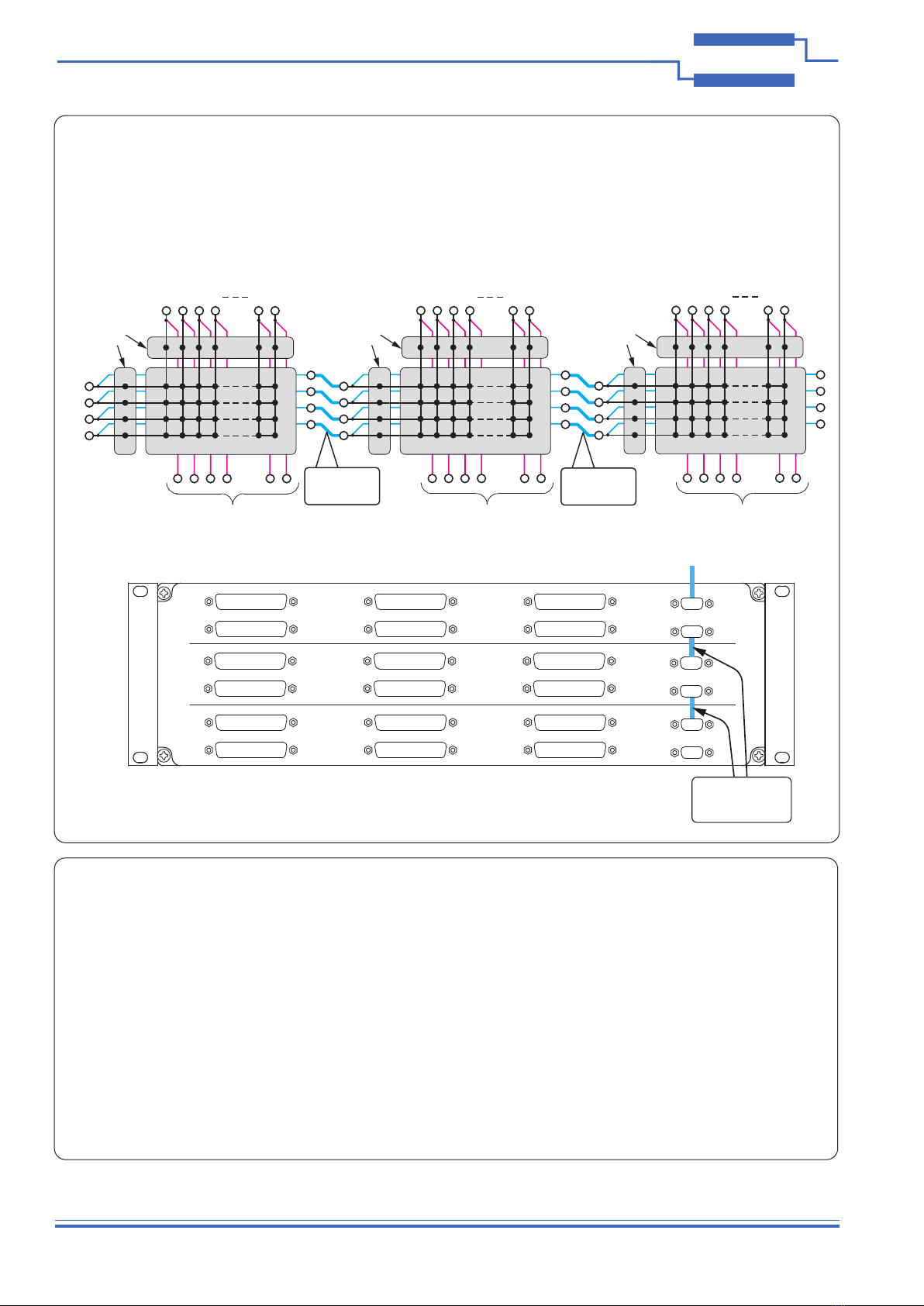
Matrix Expansion
The 60-311 may be expanded to larger matrix sizes by using cabling to daisy-chain the Loop-Thru connections.
The illustrations below show the three 75x4 matrices of a 60-311-003 interconnected as a single 225x4 matrix using female to female
9-pin D-type cables to link the Y buses. In the same way, the X Loop-Thru connections can be used to interlink the X signals and create
a matrix with a wider Y bus. Additionally, the Loop-Thru connections can be used to link X and Y buses between units. For example, ten
75x4 matrices housed in four separate 60-311 units can have their Y buses daisy-chained to produce a single 750x4 matrix.
The rst diagram shows the matrix schematic and the second diagram shows how the front panel connectors are cabled together.
X1-25 X26-50 X51-75
X76-100 X101-125 X126-150
X151-175 X176-200 X201-225
Y1-4
Female to Female
9-pin D-type
Loop-Thru Cables
Diagram showing the front panel cabling required to interconnect three 75x4 matrices
as a single 225x4 matrix. The Y-bus Loop-Thru connections can be
further expanded to other 60-311 Units.
Schematic diagram of three 75x4 matrices connected as a single 225x4 matrix
using the Y-bus Loop-Thru connections.