Pickering 41-743 User manual

Page (II) PXI PROGRAMMABLE POWER SUPPLY 41-743
pickering
Page (II) REED RELAY MODULE 40-110/115/120/125
pickering
© COPYRIGHT (2021) PICKERING INTERFACES. ALL RIGHTS RESERVED.
No part of this publication may be reproduced, transmitted, transcribed, translated or stored in any form, or by
any means without the written permission of Pickering Interfaces.
Technical details contained within this publication are subject to change without notice.
ISO 9001
Reg No. FM38792

Page (III)
PXI PROGRAMMABLE POWER SUPPLY 41-743
pickering
Page (III)
REED RELAY MODULE 40-110/115/120/125
pickering
TECHNICAL SUPPORT
For Technical Support please contact Pickering Interfaces either by phone, the website or via e-mail.
WARRANTY
All products manufactured by Pickering Interfaces are warranted against defective materials and workmanship for a period of
three years, excluding programmable power supplies, from the date of delivery to the original purchaser. Any product found to be
defective within this period will, at the discretion of Pickering Interfaces be repaired or replaced.
Products serviced and repaired outside of the warranty period are warranted for ninety days.
Extended warranty and service are available. Please contact Pickering Interfaces by phone, the website or via e-mail.
ENVIRONMENTAL POLICY
Pickering Interfaces operates under an environmental management system similar to ISO 14001.
Pickering Interfaces strives to full all relevant environmental laws and regulations and reduce wastes and releases to the
environment. Pickering Interfaces aims to design and operate products in a way that protects the environment and the health and
safety of its employees, customers and the public. Pickering Interfaces endeavours to develop and manufacture products that can
be produced, distributed, used and recycled, or disposed of, in a safe and environmentally friendly manner.
Worldwide Technical Support and Product Information
pickeringtest.com
Germany
Tel: +49 89 125 953 160
E-mail: [email protected]
Sweden
Tel: +46 340-69 06 69
E-mail: [email protected]
USA
Tel: (West) +1 541 471 0700
Tel: (East) +1 781 897 1710
E-mail: [email protected]
Czech Republic
Tel: +420 558 987 613
E-mail: [email protected]
France
Tel +33 9 72 58 77 00
E-mail [email protected]
Pickering Interfaces Headquarters
Stephenson Road Clacton-on-Sea CO15 4NL United Kingdom
Tel: +44 (0)1255-687900
E-Mail: [email protected]
China
Tel: +86 4008 799 765
E-mail: [email protected]

Page (IV) PXI PROGRAMMABLE POWER SUPPLY 41-743
pickering
Page (IV) REED RELAY MODULE 40-110/115/120/125
pickering
MEANING / DESCRIPTION SYMBOL
PROTECTIVE EARTH (GROUND)
To identify any terminal which is intended for connection to an external conductor for
protection against electric shock in case of a fault, or the terminal of a protective earth
(ground) electrode.
DANGEROUS VOLTAGE
To indicate hazards arising from dangerous voltages.
WARNING / CAUTION
An appropriate safety instruction should be followed or caution to a potential hazard
exists.
Refer to the relevant instructions detailed within the product manual.
HEAVY
If this product is heavy reference should be made to the safety instructions for
provisions of lifting and moving.
STATIC SENSITIVE
To indicate that static sensitive devices are present and handling precautions should
be followed.
!
kg
SAFETY SYMBOLS
PRODUCT SAFETY
The following safety symbols may be used on the product and throughout the product documentation.

Page (V)
PXI PROGRAMMABLE POWER SUPPLY 41-743
pickering
Copyright Statement ...................................................................II
Technical Support and Warranty................................................III
Product Safety .............................................................................IV
Contents (this page)....................................................................V
Warnings and Cautions ..............................................................VII
Section 1
Technical Specication...............................................................1.1
Section 2
Technical Description .................................................................2.1
Functional Description..........................................................2.1
Guidance on Using the Module............................................2.2
Section 3
Installation....................................................................................3.1
Pre Operation Checks...........................................................3.1
Software Installation .............................................................3.2
Hardware Installation ............................................................3.3
Soft Front Panel Installation.................................................3.4
Section 4
Programming Guide....................................................................4.1
Programming Options for Pickering PXI Modules .............4.1
Programming The 41-743 Power Supply.............................4.2
C Code Examples ..................................................................4.4
Using The Soft Front Panel ..................................................4.14
Section 5
Connector Information................................................................5.1
Section 6
Trouble Shooting.........................................................................6.1
Section 7
Maintenance Information............................................................7.1
Verication Procedure ..........................................................7.2
Verication Test Results .......................................................7.2
CONTENTS

Page (VI) PXI PROGRAMMABLE POWER SUPPLY 41-743
pickering
THIS PAGE INTENTIONALLY BLANK

Page (VII)
PXI PROGRAMMABLE POWER SUPPLY 41-743
pickering
Page (VII)
REED RELAY MODULE 40-110/115/120/125
pickering
WARNINGS AND CAUTIONS
WARNING - HAZARDOUS ENVIRONMENTS SYMBOL
atmospheres. If the product is to be used in hazardous environments we recommend that the user
ensures suitable protective measures are taken.
!
WARNING - DANGER OF ELECTRIC SHOCK SYMBOL
This module may contain hazardous voltages. Before removing the module from the rack remove all
supplies and disconnect user I/O signals.
Unused slots in the host chassis are populated with blanking plates to prevent access to user
I/O signals that may be present. Blanking panels are available to order from Pickering in a variety
of slot widths. If the product is not used in this manner for example by using an extender card then
additional care must be taken to avoid contact with exposed signals.
CAUTION - HANDLING OF ELECTROSTATIC-SENSITIVE DEVICES SYMBOL
Certain semiconductor devices used in this equipment are liable to damage due to static voltage.
Observe the following precautions when handling these devices in their unterminated state, or
sub-assemblies containing these devices:
1. Persons removing sub-assemblies from equipment using these devices must be earthed by a
wrist strap and a resistor at the point provided on the equipment.
2. Soldering irons used during the repair operations must be low voltage types with earthed tips and
isolated from the mains voltage by a double insulated transformer.
3. Outer clothing worn must be unable to generate static charges.
4.
anti-static bags.
CAUTION - PRODUCT DOCUMENTATION SYMBOL
and understood before attempting to install or operate the product.
!
SAFETY INSTRUCTIONS
SAFETY INSTRUCTIONS
All cleaning and servicing requires the equipment to be isolated and disconnected from the power source and user I/O
signals (refer to the Maintenance Section).
• Appropriate manual handling procedures should be followed as dictated by the weight of the individual module or
the combined weight of the modules & chassis.
• Should a fault occur with the module or chassis, immediately isolate and disconnect the incoming power to the
chassis and the user I/O signals.
• Ensure the equipment is installed, operated and maintained by trained and authorised personnel.
• For suitably equipped products in the event of an emergency press the red “emergency stop” button situated on
the front of the unit.

Page (VIII) PXI PROGRAMMABLE POWER SUPPLY 41-743
pickering
THIS PAGE INTENTIONALLY BLANK

Page 1.1
PXI PROGRAMMABLE POWER SUPPLY 41-743
pickering SECTION 1 - TECHNICAL SPECIFICATION
SECTION 1 - TECHNICAL SPECIFICATION
PXI Programmable Power Supply 48 V 41-743
pickeringtest.com
ISSUE 1.9 APR 2018
yFully Isolated 0 to 48 V PSU
yHigh Accuracy and Low Noise
yCurrent Capacity 2 A to 20 V, 0.8 A at 48 V
yRemote Sense Connections
yProgrammable Current Limit
yVoltage Monitor
yTrigger For Measurement Operation or Output
Update
yBackplane Power From 2 PXI Slots
yVISA & IVI Drivers Supplied For Windows
Plus Soft Front Panel
ySupported by PXI or LXI Chassis
PCI
Interface
PXI
Bus
Isolated
DC-DC
Converter
PXI Power Linear
Regulator
Isolation
Barrier
Measurement
& Control
System
Vout+
Vout-
Vsense-
Vsense+
Block Diagram for 41-743 Power Supply Module
The 41-743 is a fully isolated programmable power supply
capable of delivering voltages to 48 V with a resolution
of less than 1 mV. It can deliver up to 40 W and requires
no external power source – power is drawn from two PXI
backplane slots.
Sense connections allow the 41-743 to regulate voltages
at a remote point to improve accuracy of test results when
wiring losses are significant. The sense facility can be set
to use a remote connection or to regulate the output at the
front panel terminals.
A programmable current limit protects switching systems
and the UUT when faults cause excessive current.
A monitor facility allows the user to read the actual voltage
being supplied and the current delivered to the load.
A trigger function allows the 41-743 to execute output
current limit or voltage settings in response to a hardware
event from the front panel or from the PXI Trigger Bus. The
trigger also supports the capture of current and voltage
measurements at the output, a buffer allows results to be
stored and read when the system is ready. Measurements
can also be made at timed intervals.
Output voltage rise time is controlled to avoid excessive
inrush current damaging the switching system when
driving capacitive loads.
The 41-743 can be supported by any PXI chassis or by
Pickering Interfaces’ LXI modular chassis.

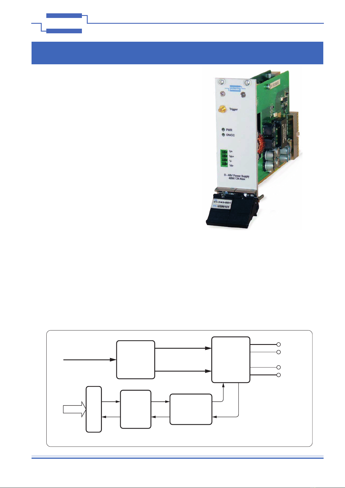
Page 1.2 PXI PROGRAMMABLE POWER SUPPLY 41-743
pickering
SECTION 1 - TECHNICAL SPECIFICATION
Programmable Power Supply 48 V, 41-743
pickeringtest.com
Specifications
Specification
Output Voltage
Range:
0 V to 48 V,
0.74 mV nominal resolution.
Output Voltage
Accuracy:
±0.2 % ±25 mV.
Voltage Slew Rate: 1 V/ms nominal at full load
Output Noise: 1.5 mVrms, 6 mV peak to peak, full load,
DC to 1 MHz.
Output Current
Range:
2 A to 20 V, de-rating linearly to
0.8 A at 48 V.
Current Limit: 0 to 2 A, 34 µA nominal resolution.
Current Limit
Accuracy:
±0.5 % of set value ±10 mA.
Voltage Sense: Voltage sense lines compensate for up
to 0.5 V voltage drop (0.25 V for each
connection), can be switched to sense
output voltage on user connector.
Current Monitor: Accuracy: ±0.2 % of reading ±5 mA
Resolution: 35 µA
Voltage Monitor: Accuracy: ±0.1 % of reading ±10 mV
Resolution: 0.74 mV
Isolation Barrier: Designed with ±250 V isolation barrier,
recommended to ±60 V relative to PXI
ground.
>100 MΩ insulation resistance from
voltage outputs to PXI ground.
Trigger Input: Front panel or PXI Trigger Bus.
Permits triggered output changes or
measurements, permits sampled output
measurements at time intervals in
multiple of 100 µs, permits a sequence
of output changes from stored settings.
Minimum trigger width 20 µs.
Front panel trigger input is optically
isolated, maximum input voltage +12 V,
50 mA.
Operating/Storage Conditions
Operating Conditions
Operating Temperature:
Humidity:
Altitude:
0 °C to +55 °C
Up to 90 % non-condensing
5000 m
Storage and Transport Conditions
Storage Temperature:
Humidity:
Altitude:
-20 °C to +75 °C
Up to 90 % non-condensing
15000 m
PXI & CompactPCI Compliance
The module is compliant with the PXI Specification 2.2.
Local Bus, Uses a 33 MHz 32-bit backplane interface.
Safety & CE Compliance
All modules are fully CE compliant and meet
applicable EU directives: Low-voltage safety EN61010-
1:2010, EMC Immunity EN61326-1:2013, Emissions
EN55011:2009+A1:2010.*
Mechanical Characteristics
Dual slot 3U PXI (CompactPCI card).
3D models for all versions in a variety of popular file
formats are available on request.
Connectors
PXI bus via 32-bit P1/J1 backplane connector.
Power supply outputs & sense: 4-pin plug-in screw
terminal block
Trigger Input: SMB coaxial connector.
For pin outs please refer to the operating manual.
41-743 Safe Operational Area
Power Requirements
+3.3 V +5 V +12 V -12 V
750 mA 12 A max
(from 2 slots)
60 mA 0
Current
2.0A
0.8A
Voltage
20V 48V

Page 1.3
PXI PROGRAMMABLE POWER SUPPLY 41-743
pickering SECTION 1 - TECHNICAL SPECIFICATION
Programmable Power Supply 48 V, 41-743
pickeringtest.com
Ordering Information
Product Order Codes
0-48Vdc Programmable Power Supply 41-743-001
Product Customization
Pickering modules are designed and manufactured on our
own flexible manufacturing lines, giving complete product
control and enabling simple customization to meet very
specific requirements.
All customized products are given a unique part number,
fully documented and may be ordered at any time in the
future. Please contact your local sales office to discuss.
Mating Connectors & Cabling
The 41-743 is supplied with a 4-pin female plug-in
connector block with screw terminals for the user to
construct their own cabling.
Pickering can supply spare 4-pin female plug-in connectors,
contact the sales office for details.

Page 1.4 PXI PROGRAMMABLE POWER SUPPLY 41-743
pickering
SECTION 1 - TECHNICAL SPECIFICATION
Programmable Power Supply 48 V, 41-743
pickeringtest.com
Supporting Products & Software
We also offer customized cabling and have a free online Cable Design Tool
that can be used to create custom cable solutions for many applications.
Visit: pickeringtest.com/cdt to start your design.
Mass Interconnect
We recommend the use of a mass interconnect solution when an
Interchangeable Test Adapter (ITA) is required for a PXI or LXI based
test system. Our modules are fully supported by both Virginia Panel and
MacPanel.
Pickering Reed Relays
We are the only switch provider with in-house reed relay manufacturing
capability via our Relay Division. These instrument grade reed relays feature
SoftCenter™ technology, ensuring long service life and repeatable contact
performance. To learn more, please go to: pickeringrelay.com
Chassis Compatibility
This PXI module must be used in a suitable chassis. It is compatible with the following chassis types:
• All chassis conforming to the 3U PXI and 3U Compact PCI (cPCI) specification
• Legacy and Hybrid Peripheral slots in a 3U PXI Express (PXIe) chassis
• Pickering Interfaces LXI or LXI/USB Modular Chassis
Chassis Selection Guide
Standard PXI or hybrid PXIe Chassis from any Vendor:
• Mix our 1000+ PXI switching & simulation modules with
any vendor’s PXI instrumentation
• Embedded or remote Windows PC control
• Real-time Operating System Support
• High data bandwidths, especially with PXI Express
• Integrated module timing and synchronization
Pickering LXI or LXI/USB Modular Chassis—only accept
our 1000+ PXI Switching & Simulation Modules:
• Ethernet or USB control enables remote operation
• Low-cost control from practically any controller
• LXI provides manual control via Web browsers
• Driverless software support
• Power sequencing immunity
• Ethernet provides chassis/controller voltage isolation
• Independence from Windows operating system
Connectivity Solutions
We provide a full range of supporting cable and connector solutions for all our switching products—20 connector families
with 1200+ products. We offer everything from simple mating connectors to complex cables assemblies and terminal blocks.
All assemblies are manufactured by Pickering and are guaranteed to mechanically and electrically mate to our modules.
Connectors & Backshells Multiway Cable Assemblies RF Cable Assemblies Connector Blocks

Page 1.5
PXI PROGRAMMABLE POWER SUPPLY 41-743
pickering SECTION 1 - TECHNICAL SPECIFICATION
Programmable Power Supply 48 V, 41-743
pickeringtest.com
Supporting Products & Software
© Copyright (2021) Pickering Interfaces. All Rights Reserved
Pickering Interfaces maintains a commitment to continuous product development, consequently we reserve the right to vary from the description given in this data sheet.
Programming
Pickering provide kernel, IVI and VISA (NI & Keysight) drivers which are compatible with all Microsoft supported versions of
Windows and popular older versions. For a list of all supporting operating systems, please see: pickeringtest.com/os
The VISA driver is also compatible with Real-Time Operating Systems such as LabVIEW RT. For other RTOS support contact
Pickering. These drivers may be used with a variety of programming environments and applications including:
• Pickering Interfaces Switch Path Manager
• National Instruments products (LabVIEW, LabWindows/CVI, Switch Executive, MAX, TestStand, VeriStand, etc.)
• Microsoft Visual Studio products (Visual Basic, Visual C+)
• Keysight VEE and OpenTAP
• Mathworks Matlab
• Marvin ATEasy
• MTQ Testsolutions Tecap Test & Measurement Suite
Drivers for popular Linux distributions are available, other environments are also supported, please contact Pickering
with specific enquiries. We provide Soft Front Panels (SFPs) for our products for familiarity and manual control, as well as
comprehensive documentation and example programs to help you develop test routines with ease.
To learn more about software drivers and development environments, please go to: pickeringtest.com/software
Signal Routing Software
Our signal routing software, Switch Path Manager, automatically selects and energizes
switch paths through Pickering switching systems. Signal routing is performed by simply
defining test system endpoints to be connected together, greatly accelerating Test System
software development. To learn more, please go to: pickeringtest.com/spm
Diagnostic Relay Test Tools
eBIRST Switching System Test Tools are designed specifically for our PXI,
PCI or LXI products, these tools simplify switching system fault-finding by
quickly testing the system and graphically identifying the faulty relay.
To learn more, please go to: pickeringtest.com/ebirst
Three Year Warranty & Guaranteed Long-Term Support
All standard products manufactured by Pickering Interfaces are warranted against defective materials and workmanship
for a period of three years from the date of delivery to the original purchaser. Extended warranty and service agreements
are available for all our modules and systems with various levels to suit your requirements. Although we offer a 3-year
warranty as standard, we also include guaranteed long-term support—with a history of supporting our products for typically
15-20 years. To learn more, please go to: pickeringtest.com/support
Available Product Resources
We have a large library of product resources including success stories, product and support videos, articles and white
papers as well as application specific product brochures to assist when looking for the switching, simulation and
connection solutions you need. We have also published handy reference books on Switching Technology and for the PXI
and LXI standards.
To view, download or request any of our product resources, please visit: pickeringtest.com/resources

Page 1.6 PXI PROGRAMMABLE POWER SUPPLY 41-743
pickering
SECTION 1 - TECHNICAL SPECIFICATION
THIS PAGE INTENTIONALLY BLANK

Page 2.1
PXI PROGRAMMABLE POWER SUPPLY 41-743
pickering SECTION 2 - TECHNICAL DESCRIPTION
SECTION 2 - TECHNICAL DESCRIPTION
FUNCTIONAL DESCRIPTION
Figure 2.1 - Programmable Power Supply Module 41-743: Functional Block Diagram
The 41-743 is a single output programmable power supply which draws its power from two slots of a PXI backplane.
The use of 2 backplane connectors minimizes stress on the backplane connectors even under maximum load
conditions on the power supply. Power is drawn from the +5V supply and provided to an isolated DC to DC converter
(variable) for regulation in a linear regulator stage. The linear regulator minimizes output noise and ripple on the
power provided to the user.
Sense lines allow the users to regulate the voltage at a remote point, compensating for voltage drops in the supply
wires. The sense wires can be congured to be uncommitted or to automatically connect to the Vout terminals if
they are not connected.
The output voltage and current load can be read back through the internal instrumentation system.
The design is fully isolated from chassis, allowing modules to be added in series for higher voltage applications.
Modules can be added in parallel to provide higher output currents with the aid of external supporting hardware.
PCI
INTERFACE
DATA
ISOLATED
DC-DC
CONVERTER
POWER LINEAR
REGULATOR
ISOLATION
BARRIER
MEASUREMENT
AND CONTROL
SYSTEM
Vout+
Vout-
Vsense-
Vsense+
PXI BUS

Page 2.2 PXI PROGRAMMABLE POWER SUPPLY 41-743
pickering
SECTION 2 - TECHNICAL DESCRIPTION
GUIDANCE ON USING THE MODULE
The power supply load should be connected directly to the Vout+ and Vout- terminals using wires appropriate for
the application. The use of heavier wire will minimise any voltage drop in the wiring and improve the performance
of the power supply.
The sense wires should be connected either directly to the Vout terminals (Vout+ to Vsense+ and Vout- to Vsense-)
if the front panel voltage is to regulated or to the load if the voltage at the load is to be controlled.
If the system is to be referenced to ground normal practice is to ground the appropriate terminal (Vout+ or Vout-) at
the load to control earth loop currents.
The sense wires can be congured to have one of two behaviours:
• If the sense wire is not connected then the power supply will not start
• If the sense wire is not connected the power supply will automatically regulate the front panel voltage
Conguration of the sense wires can be implemented under software control.
Load41-743
Sense at Front Panel
V+
Vs+
Vs-
V-
_
+
Load41-743
V+
Vs+
Vs-
V-
_
+
Sense at Load
Figure 2.2 - Using The 41-743 Power Supply Module’s Sense Connections

Page 2.3
PXI PROGRAMMABLE POWER SUPPLY 41-743
pickering SECTION 2 - TECHNICAL DESCRIPTION
For applications requiring higher output voltages modules can be placed in series with the sense lines connected at
the load and at the series connection point as shown.
For applications requiring two modules so that increased output current can be provided then use the diagram below
with the additional diodes (user supplied). The diodes should be appropriate to the current and voltage demands of
the load and must be schottky diodes to minimise voltage drops. They prevent the power supplies from interacting
and causing reliability issues. Each power supply module should be set to the same output voltage.
Figure 2.3 - Connecting Two
41-743 Modules in Series For
Increased Voltage
Load
41-743
V+
Vs+
Vs-
V-
_
+
41-743
V+
Vs+
Vs-
V-
Load41-743
V+
Vs+
Vs-
V-
_
+
41-743
V+
Vs+
Vs-
V-
Schottky
Diode
Schottky
Diode
Figure 2.4 - Connecting
Two 41-743 Modules in
Parallel For Increased
Current Capability

Page 2.4 PXI PROGRAMMABLE POWER SUPPLY 41-743
pickering
SECTION 2 - TECHNICAL DESCRIPTION
High Dynamic Loads
In applications where the load may suddenly change it will take time for the 41-743 to correct the voltage at a remote
load when using remote sensing. If the transient response is of concern it is recommended that a capacitor is added
across the load. Adding a capacitor may increase the time it takes for the power supply to discharge if the power
supply is lightly loaded and the output voltage value programmed is reduced.
Capacitor selection for a remote load can be achieved either by trial an error or by estimation using the slew rate
information (1V per ms). If a dynamic load produces a 100mV voltage change at the remote load for example then
the capacitor need to provide the charge of the load current for 0.1ms. If the load current is 1A and the acceptable
voltage change is 10mV then from the formula:
I*T=C*V
Where I is the current, T is the time taken for the power supply to correct the voltage, C is the required capacitance
and V is the allowed change voltage then an estimate of the value of C can be derived. For the above example:
1*0.0001=C*0.01 or 10,000µF
Minimizing supply wire resistance can have a large impact on the value of capacitance needed.

Page 3.1
PXI PROGRAMMABLE POWER SUPPLY 41-743
pickering SECTION 3 - INSTALLATION
Page 3.1
REED RELAY MODULE 40-110/115/120/125
pickering SECTION 3 - INSTALLATION
kg
PREOPERATION CHECKS (UNPACKING)
1. Check the module for transport damage and report any damage immediately to Pickering Interfaces.
Do not attempt to install the product if any damage is evident.
2. Position the chassis relative to any other equipment the module(s) will connect with. Ensure the chassis is not
connected to the electrical supply.
3. Ensure that the designated area for the chassis containing the module is of at and solid construction to
withstand and support the combined weight of the module(s) and chassis.
SECTION 3 - INSTALLATION
!
Refer to the Warnings and Cautions at the front of this manual
Modular products require installation in a suitable PXI/LXI chassis. The module is designed for indoor use only.
Figure 3.1 - Installing the Module into a PXI/cPCI/LXI Chassis
PXI / LXI Chassis

Page 3.2 PXI PROGRAMMABLE POWER SUPPLY 41-743
pickering
SECTION 3 - INSTALLATION
SOFTWARE INSTALLATION
The PXI software installation should be carried out before the hardware install so that the Pickering PXI device
is subsequently detected correctly by the Windows hardware install wizard. If you install the hardware rst the
Pickering device may subsequently be detected incorrectly. If this happens you will need to install the software
driver and then use Windows device manager to “uninstall” the device and either “scan for hardware changes” or
re-boot.
LXI hardware devices (including PXI cards in an LXI modular chassis) can be installed before or after the software
drivers.
The software device drivers can be found on the Pickering Installation disk provided or downloaded from either
http://www.pickeringtest.info/downloads or http://www.pickeringtest.com. If you download the driver then unzip it
and run the appropriate “setup” program.
To install from DVD place the Pickering “Software Installation disk” in your DVD drive, it should auto load and display
a web browser Menu, if not use Windows explorer to navigate to the DVD root and double click “index.html”. Select
“Drivers” then “PCI and PXI Instrument Cards” from the Menu and then click the driver icon for the 41-743. This will
start the software driver installation. During the installation you will be asked to choose VISA or Direct driver. If you
do not know which driver to use consult the “Drivers” topic in the “Programming section”.
When installation completes, the installed drivers’ ReadMe le is offered for display. It can also be displayed later
using a shortcut on the Programs>>Pickering menu.
If you are not a LabVIEW user you should choose the “full” version, and once that has been installed run the
LabVIEW Runtime Engine installer via the shortcut on the Programs>>Pickering menu. In the absence of LabVIEW
the Runtime Engine is required to support the Pickering Test Panels application.
Quick Installation Steps
The following steps are a fast track to installing your Pickering device Software and Hardware components in the
correct order. You are also advised to read the Software and Hardware Installation topics, especially if you have
never installed a hardware device before.
1. Place the Pickering “Software Installation disk” in your DVD drive, it should auto load and display a web
browser Menu, if not use Windows explorer to navigate to the DVD root and double click “index.html”.
2. Select “Drivers” then “PCI and PXI Instrument Cards” from the Menu then click the driver icon for the
41-743. This will start the software driver installation.
3. During the installation you will be asked to choose VISA or Direct driver. If you do not know which driver to
use consult the “Drivers” topic in the “Programming section”.
4. Shutdown Windows and power off your PC and PXI chassis and install the 40-743 in your PXI chassis.
5. Switch on your PXI chassis wait for its status led’s to settle then switch on the PC.
6. Windows Hardware Wizard will detect new hardware, do not choose “Widows Update” press next and
choose “automatic” before continuing.
Installation is now complete and the 41-743 should be listed in device manager.
Table of contents
Other Pickering Power Supply manuals
Popular Power Supply manuals by other brands

POWEROLOGY
POWEROLOGY MAGSAFE PWCUQC014 quick start guide

Altronix
Altronix TROVE Trove1SP1 installation guide

Pulsar
Pulsar R812P quick start guide

Manson Engineering Industrial
Manson Engineering Industrial HCS-3302-USB user manual

Antec
Antec HCG-750 user manual

Voodoo Lab
Voodoo Lab Pedal Power 3 Plus manual