Pickering PCIe 41-924 User manual

Page (ii)
© Copyright (2023) Pickering Interfaces. All Rights Reserved.
No part of this publication may be reproduced, transmitted, transcribed, translated or stored in any form, or by any
means without the written permission of Pickering Interfaces.
Technical details contained within this publication are subject to change without notice.
FM38792

Page (iii)
Worldwide Technical Support and Product Information
Pickering Interfaces Headquarters
Stephenson Road, Clacton-on-Sea, CO15 4NL United Kingdom
Tel: +44 (0)1255-687900
e-mail: [email protected]
USA
Tel: (West) +1 541 471 0700
Tel: (East) +1 781 897 1710
e-mail: ussales@pickeringtest.com
France
Tel +33 9 72 58 77 00
e-mail: [email protected]
Germany
Tel: +49 89 125 953 160
e-mail: [email protected]
Sweden
Tel: +46 340-69 06 69
e-mail: [email protected]
Czech Republic
Tel: +420 558 987 613
e-mail: [email protected]
China
Tel: +86 4008 799 765
e-mail: [email protected]
Technical Support
For Technical Support please contact Pickering Interfaces either by phone, the website or via e-mail.
Warranty
All products manufactured by Pickering Interfaces are warranted against defective materials and workmanship for a period
of three years, excluding programmable power supplies, from the date of delivery to the original purchaser. Any product
found to be defective within this period will, at the discretion of Pickering Interfaces be repaired or replaced.
Products serviced and repaired outside of the warranty period are warranted for ninety days.
Extended warranty and service are available. Please contact Pickering Interfaces by phone, the website or via e-mail.
Environmental Policy
Pickering Interfaces operates under an environmental management system similar to ISO 14001.
Pickering Interfaces strives to fulfil all relevant environmental laws and regulations and reduce wastes and releases to the
environment. Pickering Interfaces aims to design and operate products in a way that protects the environment and the health
and safety of its employees, customers and the public. Pickering Interfaces endeavours to develop and manufacture products
that can be produced, distributed, used and recycled, or disposed of, in a safe and environmentally friendly manner.

Page (iv)
Meaning/Description Symbol
PROTECTIVE EARTH (GROUND)
To identify any terminal which is intended for connection to an
external conductor for protection against electric shock in case of a
fault, or the terminal of a protective earth (ground) electrode.
DANGEROUS VOLTAGE
To indicate hazards arising from dangerous voltages.
WARNING/CAUTION
An appropriate safety instruction should be followed or caution to a
potential hazard exists.
Refer to the relevant instructions detailed within the product
manual.
HEAVY
If this product is heavy reference should be made to the safety
instructions for provisions of lifting and moving.
STATIC SENSITIVE
To indicate that static sensitive devices are present and handling
precautions should be followed.
!
kg
Safety Symbols
The following safety symbols may be used on the product and throughout the product documentation.
Product Safety

Page (v)
Contents
Copyright Statement........................................................................................................................................................(ii)
Technical Support and Warranty...................................................................................................................................(iii)
Product Safety...................................................................................................................................................................(iv)
Contents (this page).........................................................................................................................................................(v)
Warnings and Cautions...................................................................................................................................................(vi)
Section 1
Technical Specification....................................................................................................................................................1.1
Section 2
Technical Description ......................................................................................................................................................2.1
Hardware Description................................................................................................................................................2.1
51-924 Layout Connectors & Indicators..................................................................................................................2.1
41-924 Layout Connectors & Indicators..................................................................................................................2.3
Section 3
Installation.........................................................................................................................................................................3.1
Pre Operation Checks ................................................................................................................................................3.1
Installation of 51-924 in Host PC .............................................................................................................................3.1
Installation of 41-924 in PXI Chassis.......................................................................................................................3.3
Cabling Host Computer to a PXI Chassis................................................................................................................3.5
Power ON/OFF Sequence..........................................................................................................................................3.7
Status LED Indicators ................................................................................................................................................3.7
Section 4
Trouble Shooting..............................................................................................................................................................4.1
Section 5
Maintenance Information................................................................................................................................................5.1

Page (vi)
WARNING - Hazardous Environments Symbol
This product is not specifically designed for use in hazardous environments, for example in explosive
atmospheres. If the product is to be used in hazardous environments we recommend that the user ensures
suitable protective measures are taken.
!
CAUTION - Handling of Electrostatic-Sensitive Devices Symbol
Certain semiconductor devices used in this equipment are liable to damage due to static voltage. Observe the
following precautions when handling these devices in their unterminated state, or sub-assemblies containing
these devices:
• Persons removing sub-assemblies from equipment using these devices must be earthed by a wrist strap
and a resistor at the point provided on the equipment.
• Soldering irons used during the repair operations must be low voltage types with earthed tips and isolated
from the mains voltage by a double insulated transformer.
• Outer clothing worn must be unable to generate static charges.
• Printed Circuit Boards (PCBs) fitted with these devices must be stored and transported in anti-static bags.
Warnings & Cautions
WARNING - Danger of Electric Shock Symbol
This module may contain hazardous voltages. Before removing the module from the rack remove all supplies
and disconnect user I/O signals.
Unused slots in the PXI/PXIe/LXI chassis are populated with blanking plates to prevent access to user I/O
signals that may be present. Blanking panels are available to order from Pickering in a variety of slot widths.
If the product is not used in this manner for example by using an extender card then additional care must be
taken to avoid contact with exposed signals.
CAUTION - Product Documentation Symbol
Suitably qualified & trained users should ensure that the accompanying documentation is fully read and
understood before attempting to install or operate the product.
!
Safety Instructions
Safety Instructions
All cleaning and servicing requires the equipment to be isolated and disconnected from the power source and user I/O signals
(refer to the Maintenance Section).
• Appropriate manual handling procedures should be followed as dictated by the weight of the individual module or the
combined weight of the modules & chassis.
• Should a fault occur with the module or chassis, immediately isolate and disconnect the incoming power to the chassis and
the user I/O signals.
• Ensure the equipment is installed, operated and maintained by trained and authorised personnel.
• For suitably equipped products in the event of an emergency press the red “emergency stop” button situated on the front of
the unit.

Page 1.1 pickeringtest.com
Section 1 - Technical Specification
yProvides Seamless Interface Between PC
Controller PCIe and PXI Chassis
yFast PCI Express Interface
ySupports 32 bit 33 MHz PXI Bus
ySupplied Complete with Interface Cable
yLow Power Consumption
yOccupies Single PXI and PCIe Slot
y3 Year Warranty
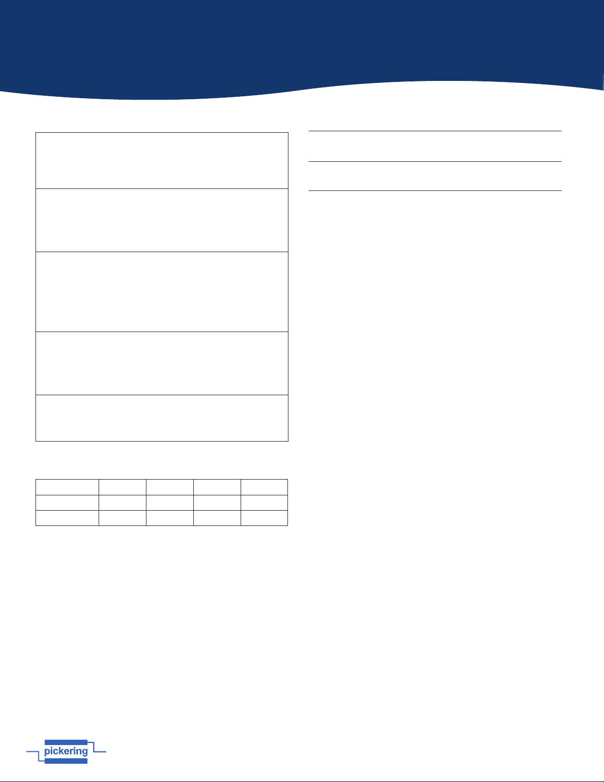
Diagram Showing Remote Control Interface Kit Fitted in a Controlling PC and a PXI Chassis, Linked With the Interface Cable
Controller PC
Interface Cable
51-924-001 Card
(Installed in PCI Express
Slot in Host Computer)
41-924-001 Module
(Installed in System
Slot in PXI Chassis)
12 3 4 5 6 7
PXI Chassis
8 9 10 11 12 13 14 15 16 17 18 19
Harnessing the bandwidth potential of PCI Express, the
41-924 Extension Kit enables computers with a PCIe slot to
remotely control a PXI chassis via a high-speed interface. The
extension system operates in 32-bit/33 MHz configuration
and has complete end-to-end hardware and software
transparency for the host system. Hardware installed in the
PXI chassis operates as if it is installed in the host system,
requiring no additional drivers or software.
The host system can be separated from the PXI chassis by up
to 7 meters using a high-quality shielded twisted pair cable.
Controlling PXI™ with PCI Express®
Based on PCI Express technology, the PCIe-to-PXI Extension
Kit provides bus expansion capability through its high-speed
differential signal interface. With the 41-924 Extension Kit,
users can use a PCIe slot to control an external PXI chassis.
Because the PCIe bridge is transparent, there is no need to
install any additional software on the external chassis.
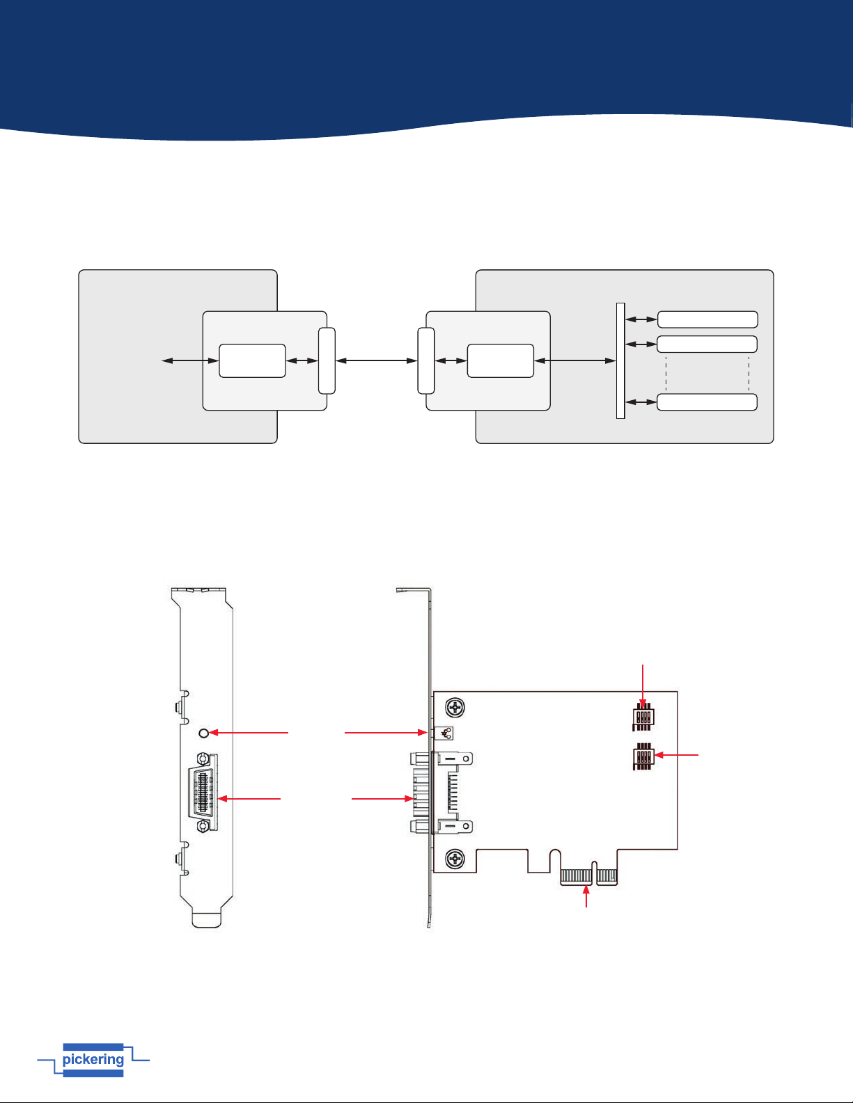
The Extension Kit consists of a 50-924-001 card installed in the
host computer, a shielded interface cable, and a 40-924-001
module installed in the remote PXI chassis. The 50-924-001 has
a PCIe x1 footprint and communicates with the 40-924-001 via
the interface cable. The 40-924-001 converts the PCIe interface
into a PCI interface for the PXI slots in the extension system.
The link between host PC and the external chassis is a PCI
Express X1 link that consists of a dual-simplex communications
channel with two, low-voltage differentially driven signal pairs.
The signaling rate can be up to 2.5 Gbps in each direction. With
a shielded twisted pair cable, the maximum extension distance
is up to 7 m without decreasing signal rate.
pickeringtest.com
41-924
PCIe to PXI Remote Control Interface
Issue 3.0 August 2023

Page 1.2 pickeringtest.com
Section 1 - Technical Specification
Power Requirements
+3.3 V +5 V +12 V -12 V
51-924-001 210 mA 0 0 0
41-924-001 720 mA 0 0 0
Mechanical Characteristics
51-924-001: Single slot PCIe Card
(height 68.90mm, width 86.65mm)
41-924-001: Single slot 3 U PXI (CompactPCI card).
3D models for all versions in a variety of popular file formats
are available on request.
Operating/Storage Conditions
Operating Temperature:
Humidity:
Altitude:
0 °C to +50 °C
Up to 90 % non-condensing
5000 m
Storage Temperature:
Humidity:
Altitude:
-20 °C to +80 °C
Up to 90 % non-condensing
15000 m
Safety & CE Compliance
All modules are fully CE compliant and meet applicable
EU directives:
Low-voltage safety EN61010-1:2010,
EMC Immunity EN61326-1:2013,
Emissions EN55011:2009+A1:2010.
Specification
The system is supplied as kit containing an interface cable,
a 41-924-001 PXI module and a 51-924-001 PCIe card and
ordered as a complete kit. Provides a single lane PCIe
connection from PCIe to PXI.
51-924-001 Specification:
Compliant with PCI Express Base Specifications Rev. 1.0a.
PCI Express x1 link providing an effective signaling rate of
up to 2.5 Gigabits/sec.
41-924-001 Specification:
Compliant with PCI-to-PCI Bridge Architecture Specification
Rev. 1.2.
Supports 5 V and 3.3 V PCI bus
32-bit/33 MHz full data throughput.
Chassis Compatibility:
51-924-001 is suitable for insertion in any PCIe slot of a PC.
41-924-001 is suitable for insertion in any PXI chassis
controller slot (Slot 1), not suitable for PXIe controller slots.
Connection Distance:
Supplied with a 3 m interface cable, maximum connection
distance of 7 m.
Product Order Codes
PCIe to PXI Remote Control Kit 41-924-001-KIT
(Complete kit 51-924-001, 41-924-001, 3m Interface cable)
PCIe Remote Control Interface Card
PXI Remote Control Interface Module
51-924-001
41-924-001
41-924
pickeringtest.com Page 2
Specifications & Ordering Information

Page 2.1 pickeringtest.com
Section 2 - Technical Description
Hardware Description
Figure 2.1 - PCI Express-to-PXI Extension Kit Functional Block Diagram
PXI Slot 1
PXI Slot 2
PXI Slot n
PCI Express
to PCI Bridge
41-924-001
Remote PXI Chassis
32-bit
/33MHz
PCI Bus
Signal
Equalizer
51-924-001
External CableX1 PCI Express
Host PC
Receive Signal
Equalisation
Adjustment
Switches
PCI Express Edge
Connector
Functional Block Diagram
51-924 Layout Connectors & Indicators
Figure 2.2 - 51-924 PCIe Remote Control Interface Card Mechanical Layout
PCI Express
Serial Link
Connector
Serial Link
Status
Indicator
Transmit Signal
Equalisation
Adjustment
Switches
S2
S1

Page 2.2 pickeringtest.com
Section 2 - Technical Description
51-924-001 S1/S2 Signal Equalizer Adjustments
51-924-001 provides equalization, amplification and de-emphasis circuits to optimize signal integrity performance. With this
design, 51-924-001 allows signal transmission over long distances and reduces signal distortion.
Note:
The following adjustment should be applied to both S1 and S2 simultaneously. S1 adjusts transmits signals and S2 adjusts
receive signals.
Table 2.1 - S1/S2 51-924-001 Equalization Selection
Setting Description
Strongest equalizer levels (default)
Moderate equalizer level
Weakest equalizer level
No equalizer
ON
1 2
3
4
ON
1 2
3
4
ON
1 2
3
4
ON
1 2
3
4
ON
1
2
3
4
ON
1
2
3
4
ON
1
2
3
4
ON
1
2
3
4
Table 2.2 - S1/S2 51-924-001 Output Swing Control
Setting Description
High level output signal swing (default)
Normal level output signal swing
Table 2.3 - S1/S2 51-924-001 Output De-Emphasis Control
Setting Description
High level (default)
Normal level

Page 2.3 pickeringtest.com
Section 2 - Technical Description
41-924 Layout Connectors & Indicators
Figure 2.3 - 41-924 PXIe Remote Control Interface Module Mechanical Layout
Spread
Spectrum Clock
Control Link
PCI Express
Serial Link
Connector
Serial Link
Status
Indicator
Table 2.4 - J1 41-924-001 Spread Spectrum Clock Control
Setting Description
Enables spread spectrum control. When enabling
spread spectrum control, the PCI clock will be
modulated with a low frequency carrier, the peak
EMI can be greatly reduced in the system (Default).
Disables spread spectrum control.
123
123
J1

Page 3.1 pickeringtest.com
Section 3 - Installation
kg
Pre-operation Checks (Unpacking)
1. Check the module for transport damage and report any damage immediately to Pickering Interfaces.
Do not attempt to install the product if any damage is evident.
2. Position the chassis relative to any other equipment the module(s) will connect with. Ensure the chassis
is not connected to the electrical supply.
3. Ensure that the designated area for the chassis containing the module is of flat and solid construction to
withstand and support the combined weight of the module(s) and chassis.
!
Refer to the Warnings and Cautions at the front of this manual
These products require installation in a suitable PXIe chassis/host PC. They are designed for indoor use only.
!
Installation of 51-924-001 in Host PC
The host PC must be electrically installed in accordance with local regional electrical codes by a qualified engineer.
The PC must be grounded.
Electrostatic discharge can damage the components on the card.
To avoid such damage in handling the board refer to page vi.
Ensure that there is adequate ventilation.
The card should be installed in accordance with the following procedure:
1. Ensure that the PC is turned OFF but still connected to mains so that it remains grounded.
2. Unscrew the fixing screws and remove the cover of you host PC to gain access to the backplane
3. Choose an available x1 PCI Express slot in the PC backplane.
4. Remove the blanking panel for the chosen slot and retain the fixing screw.
5. Carefully remove the 51-924-001 card from its anti-static bag and insert the card’s edge connector into
the chosen slot on the backplane (refer to Figure 3.1).
6. Make sure the card is fully inserted into the edge connector and its front panel is fully in contact with
the back of the card aperture of the host PC’s chassis.
7. Use the fixing screw to secure the front panel of the card to the chassis mounting rail.
8. Replace the cover of the host PC and secure with the appropriate fixing screws.

Page 3.3 pickeringtest.com
Section 3 - Installation
!
Installation of 41-924-001 in PXI Chassis
The chassis must be electrically installed in accordance with local regional electrical codes by a qualified engineer.
The chassis must be grounded.
Electrostatic discharge can damage the components on the module.
To avoid such damage in handling the board refer to page vi.
Ensure that there is adequate ventilation.
The module should be installed in accordance with the following procedure:
1. Ensure that the chassis is turned OFF but still connected to mains so that it remains grounded.
2. Locate the system slot in the PXI chassis (the 41-924-001 module must be installed in a system
controller slot).
3. Remove the blanking plate for the system slot.
4. Ensure that the injector/ejector handle is in its downward position. Align the module with the card
guides on the top and bottom of the slot.
Do not raise the injector/ejector handle whilst inserting the module as the module will not insert
properly.
5. Hold the handle whilst slowly sliding the module into the card guides until the handle catches on the
injector/ejector rail (refer to Figure 3.2).
6. Raise the injector/ejector handle until the module firmly seats into the backplane. The front panel of the
module should be flush with the front panel of the chassis.
7. Secure the module to the chassis mounting rails using the fixing screws on the top and bottom of the
module’s front panel.

Page 3.4 pickeringtest.com
Section 3 - Installation
Figure 3.2 - Installing the 41-924-001 PXIe Remote Control Interface Module into a PXIe Chassis
Note: The 41-924-001 module must be installed in the PXIe System Controller Slot
of the chassis - peripheral slots cannot be used
PXI
Chassis
41-924-001
Remote Control
Interface Module
System
Controller Slot
Ejector
Handle
Injector/Ejector
Rail

Page 3.5 pickeringtest.com
Section 3 - Installation
Cabling Host Computer to a PXI Chassis
Now that you have successfully installed the 51-924-001 into the Host computer and installed the 41-924-001 in the PXI
chassis, you may connect the host PC and PXI chassis with the interface cable assembly.
Figure 3.3 - 3m Interface Cable Assembly
1. Locate your 3m interface cable assembly
2. Connect the cable assembly to the PCIe connector on the bracket of the 51-924-001 located in the host PC.
3. Firmly attach the 3m interface cable by tightening its retention screws.
Figure 3.4 - Connecting the 3m Interface Cable Assembly to the 51-924-001 Installed in the Host PC
!
Caution: DO NOT remove the interface cable assembly after the system is powered on may cause system
errors or data loss. If the cable is unplugged improperly, reconnect it and reboot the host PC and PXI chassis.

Page 3.6 pickeringtest.com
Section 3 - Installation
4. Connect the other end of the cable assembly to the connector of the 41-924-001 installed into the system slot of the PXI
chassis.
Figure 3.5 - Connecting the 3m Interface Cable Assembly to the 41-924-001 Installed in the PXI Chassis
Figure 3.6 - Host PC Connected to the PXI Chassis

Page 3.7 pickeringtest.com
Section 3 - Installation
Power ON/OFF Sequence
To power-on the PCIe to PXI Extension Kit:
1. Ensure that the interface cable is properly connected to the host PC and PXI chassis.
2. Power on the PXI chassis first.
3. Power on the host PC
Status LED Indicators
The LEDs on the front panel of the 51-924-001 and 41-924-001 give power status information. The LEDs light up only when
the following conditions are met:
• The extension cable between the 51-924-001 (Host PC) and 41-924-001 (Extension Chassis) is properly connected.
• The extension chassis is powered on.
• The host PC is entering its Power-On Self Test (POST).
!
Caution: DO NOT remove the cable after the system and PXI chassis are powered on. Disconnecting the cable
while the system is running may cause unpredictable system errors and/or system crash.
As the PCIe to PXI Extension Kit is a standard PCIe-to-PCI bridge interface, the BIOS will identify each device behind the
PCI bridge and assign resource to each one during start up. Thus users have to power-on the PXI™ chassis first in order to
get appropriate resources from the BIOS.
To power down the PCIe to PXIe Extension Kit:
4. Power down the host PC.
5. Power down the PXI chassis.
!
Caution: DO NOT power down the PXI chassis until the host PC is powered off. If the PXIe chassis is powered
off while the host PC is on, the host PC may hang or crash.

Page 4.1 pickeringtest.com
Section 4 - Troubleshooting
This section describes frequently asked questions that may assist in solving minor problems that may be encountered.
Question: What is the maximum extension length of the 41-924-001-KIT?
Answer: Pickering provides an interface cable in a 3 meter length, maximum cable length is 7 meters.
Question: When using the 41-924-001-KIT, are there any additional drivers or software required to install?
Answer: It is designed to be a standard PCI Express®-to-PCI bridge. It is not necessary to install additional drivers or
software for support.
Question: How many extension chassis can I connect to a host PC by using the 41-924-001-KIT?
Answer: Due to the point-to-point architecture of PCI Express®, only one PCI Express® Bus Extension Product can be
supported by one chassis. However, users can select multiple extension chassis for different purposes. For example, a
4-slot extension chassis provides small and compact form factor while an 18-slot extension chassis provides more PCI
slots. Theoretically, PCI specification allows up to 255 PCI bus segments. PCI Express® Bus Extension Products do not limit
the bus segment number. The maximum PCI bus segments may limited by your BIOS or operating system.
Question: Are there any compatibility problems with the 41-924-001-KIT?
Answer: The 41-924-001-KIT is designed as a standard PCI Express®-to-PCI Bridge. During PC boot up, your PC BIOS
will search devices and assign resources such as, I/O, memory space and IRQ number, to each device according to its
algorithm. Although PCI specification allows up to 255 bus segments in a PC system, the BIOS may not assign the correct
and/or proper resource to each device in some complex PCI systems.
Because the PCI Express® specification was released in 2002, most hardware and circuit board designers as of yet do not
offer multiple PCI-to-PCI bridges. Most BIOS work for simple applications but may not work for multiple PCI bus segments
and a variety of resource requests. We suggest customers choose PC equipment with Intel 945, 965 or later chipsets to
adjust for these issues.
Question: If I encounter compatibility problems, what should I do?
Answer: Because most compatibility problems come from PCI resource assignments, customers should consult their PC
vendors or BIOS vendors for help. Updating to the most current BIOS version may also resolve PCI resources problems.
The following list are some indications that may help customers to deal with compatibility issues:
• Disable the onboard device functions of your host PC to release IO resources.
• Remove PCI devices plugged/installed in your host PC.
• Connect an extension chassis which is single bus segment to the host PC. Plug a PCI device to an extension chassis one
by one and boot each in sequence to check if your host PC can accommodate the PCI device or not.
• You may try to plug the PCI Express® extension host card to a different PCI Express® slot.

Page 5.1 pickeringtest.com
Section 5 - Maintenance Information
General Cleaning
• Isolate the electrical power from the chassis and ensure that no user I/O signals are being applied.
• Wipe the product & chassis surfaces with a clean dry anti-static cloth only.
Software Update
For PXI/PXIe modules operating in a PXI/PXIe chassis, no module software updates are required. For the latest
version of the driver please refer to our web site pickeringtest.com where links to our Software Download page
will provide the latest version of the driver software for the various programming environments encountered.
For PXI modules which are supported in one of Pickering Interfaces’ Modular LXI Chassis (such as the 60-102B
and 60-103B) no module software update is required. If the module was introduced after the LXI chassis was
manufactured the module may not be recognized, in this case the chassis firmware may need upgrading. This is a
simple process which is described in the manual for the Modular LXI Chassis.
Periodic Maintenance
This product and its corresponding chassis do not require any periodic maintenance.
!
Refer to the Warnings and Cautions at the front of this manual.
Table of contents
Other Pickering Recording Equipment manuals
Popular Recording Equipment manuals by other brands

Zoom
Zoom G3 Operation manual

Bespoke
Bespoke BP-C9WY-6973-U installation guide

Pacific Recorders & Engineering Corporation
Pacific Recorders & Engineering Corporation BMX Technical manual

Korg
Korg electribe sampler Parameter guide

Marani
Marani DPA-260A user manual

Denon
Denon CDR-WI500 operating instructions