pico Technology PicoDiagnostics NVH User manual

PicoDiagnostics®
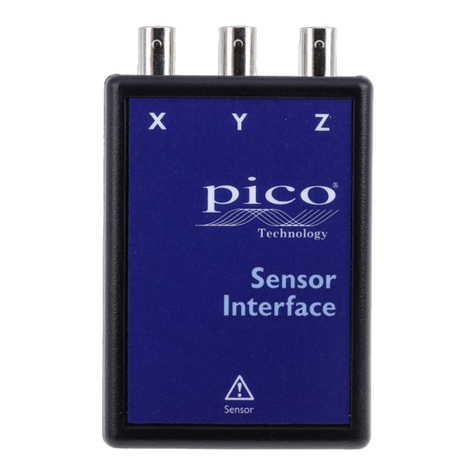
NVH Interface
Quick Start Guide
English (USA)

Pico Technology Quick Start Guide
DO210-9 3
3. Battery replacement
1. Place the NVH Interface face down and remove the four securing screws.
2. Remove the base cover from the NVH Interface.
3. Lift the old battery away from the connections.
4. Place the new battery in position. Make sure it has
the correct orientation.
5. Replace the base cover and secure it.
4. Connections
1. Connect the oscilloscope to your computer with the blue
USB cable supplied with the oscilloscope.
2. Connect the NVH Interface box to the PicoScope with the supplied BNC cables.
You will require one BNC cable when you use a microphone and up to three when
you use an accelerometer.
3. Connect either the microphone (a) or the accelerometer (b) to the NVH Interface.
Note: The extension cable provided may be used to extend the reach of either the
microphone or the accelerometer.
4. Run the PicoDiagnostics software.
5. NVH Magnet mounting instructions
1. 'LIGOXLEXXLIQSYRXMRKWYVJEGIJSVIEGLQEKRIXMWƽEXERHJVIIJVSQ
contamination.
2. Slide the keeper off the mounting magnet(s).
3. Mount the magnet/sensor assembly to the prepared test surface by gently rolling
it into place. This will avoid damaging the surface.
Note: ;MXLERSRQIXEPPMGWYVJEGIWYGLEWEPPS]WYFJVEQIWMXQE]FITSWWMPFPIXSƼ\E
small steel disk to the chassis with cyanoacrelate glue that you can use as a mounting
location.
3 Channel
NVH
Interface
XYZ
(a)
3 Channel
NVH
Interface
XYZ
TA143
Y
X
Z
(b)
PicoDiagnostics NVH interface Pico Technology
2 DO210-9
1. Introduction
Thank you for buying a PicoDiagnostics NVH Kit. This Quick Start Guide will help you set
up your NVH Interface(s) and your PicoScope Automotive Oscilloscope. In conjunction
with this guide, please also see the NVH help within the PicoDiagnostics software.
2. Safety warnings
Please review the following safety precautions to avoid injury and prevent damage to
your NVH equipment.
%;%62-2+MHIRXMƼIWGSRHMXMSRWSVTVEGXMGIWXLEXGSYPHVIWYPXMRMRNYV]SVHIEXL
%'%98-32MHIRXMƼIWGSRHMXMSRWSVTVEGXMGIWXLEXGSYPHVIWYPXMRHEQEKIXSXLITVSHYGX
or equipment to which it is connected.
WARNING
WARNING
7XVSRKQEKRIXMGƼIPHWQE]EJJIGXSVHMWEFPIXLISTIVEXMSRSJTEGIQEOIVW
ICDs and other implanted medical devices. To avoid injury or death do not
YWIXLMWTVSHYGXMJ]SYSVSXLIVTISTPIRIEVF]EVIƼXXIH[MXLWYGLHIZMGIW
The magnet can attract metallic objects or other magnets from large
distances, causing trapping injuries unless care is taken when handling.
WARNING
To avoid an accident do not operate PicoDiagnostics or the kit while driving
the vehicle. Take a passenger with you to operate the software.
CAUTION
To prevent damage or measurement errors make sure that you only use
WIRWSVWETTVSZIHF]4MGSɸ8IGLRSPSK][MXLXLMWYRMX
To avoid entrapment take care to route any cables away from moving parts
when you use the propshaft balancing accessories.
To avoid melting of cables take care to route them away from hot engine
components when you use this product.
In order to protect the NVH magnet as well as nearby objects, make sure that
XLIOIITIVMWƼXXIHXSXLIQEKRIX[LIRMXMWWXSVIHSVMRXVERWMX
To conserve battery life do not store the NVH interface with a sensor
connected. The interface is powered on whenever the sensor is connected.
Do not apply a voltage to the BNC or sensor connectors on the NVH
interface. The BNC connectors are outputs only.
7XVSRKQEKRIXMGƼIPHWGERHEQEKIWIRWMXMZIIPIGXVSRMGHIZMGIWERH
magnetic material such as credit cards or portable storage media.
Your help and efforts are required to protect and keep our environment clean.
Therefore either return these product at the end of life to the manufacturer or
ensure WEEE compliant collection and treatment yourself. Do not dispose of
as unsorted municipal waste.
DO347
Pico Technology Quick Start Guide
DO210-9 3
3. Battery replacement
1. Place the NVH Interface face down and remove the four securing screws.
2. Remove the base cover from the NVH Interface.
3. Lift the old battery away from the connections.
4. Place the new battery in position. Make sure it has
the correct orientation.
5. Replace the base cover and secure it.
4. Connections
1. Connect the oscilloscope to your computer with the blue
USB cable supplied with the oscilloscope.
2. Connect the NVH Interface box to the PicoScope with the supplied BNC cables.
You will require one BNC cable when you use a microphone and up to three when
you use an accelerometer.
3. Connect either the microphone (a) or the accelerometer (b) to the NVH Interface.
Note: The extension cable provided may be used to extend the reach of either the
microphone or the accelerometer.
4. Run the PicoDiagnostics software.
5. NVH Magnet mounting instructions
1. 'LIGOXLEXXLIQSYRXMRKWYVJEGIJSVIEGLQEKRIXMWƽEXERHJVIIJVSQ
contamination.
2. Slide the keeper off the mounting magnet(s).
3. Mount the magnet/sensor assembly to the prepared test surface by gently rolling
it into place. This will avoid damaging the surface.
Note: ;MXLERSRQIXEPPMGWYVJEGIWYGLEWEPPS]WYFJVEQIWMXQE]FITSWWMPFPIXSƼ\E
small steel disk to the chassis with cyanoacrelate glue that you can use as a mounting
location.
3 Channel
NVH
Interface
XYZ
(a)
3 Channel
NVH
Interface
XYZ
TA143
Y
X
Z
(b)
PicoDiagnostics NVH interface Pico Technology
2 DO210-9
1. Introduction
Thank you for buying a PicoDiagnostics NVH Kit. This Quick Start Guide will help you set
up your NVH Interface(s) and your PicoScope Automotive Oscilloscope. In conjunction
with this guide, please also see the NVH help within the PicoDiagnostics software.
2. Safety warnings
Please review the following safety precautions to avoid injury and prevent damage to
your NVH equipment.
%;%62-2+MHIRXMƼIWGSRHMXMSRWSVTVEGXMGIWXLEXGSYPHVIWYPXMRMRNYV]SVHIEXL
%'%98-32MHIRXMƼIWGSRHMXMSRWSVTVEGXMGIWXLEXGSYPHVIWYPXMRHEQEKIXSXLITVSHYGX
or equipment to which it is connected.
WARNING
WARNING
7XVSRKQEKRIXMGƼIPHWQE]EJJIGXSVHMWEFPIXLISTIVEXMSRSJTEGIQEOIVW
ICDs and other implanted medical devices. To avoid injury or death do not
YWIXLMWTVSHYGXMJ]SYSVSXLIVTISTPIRIEVF]EVIƼXXIH[MXLWYGLHIZMGIW
The magnet can attract metallic objects or other magnets from large
distances, causing trapping injuries unless care is taken when handling.
WARNING
To avoid an accident do not operate PicoDiagnostics or the kit while driving
the vehicle. Take a passenger with you to operate the software.
CAUTION
To prevent damage or measurement errors make sure that you only use
WIRWSVWETTVSZIHF]4MGSɸ8IGLRSPSK][MXLXLMWYRMX
To avoid entrapment take care to route any cables away from moving parts
when you use the propshaft balancing accessories.
To avoid melting of cables take care to route them away from hot engine
components when you use this product.
In order to protect the NVH magnet as well as nearby objects, make sure that
XLIOIITIVMWƼXXIHXSXLIQEKRIX[LIRMXMWWXSVIHSVMRXVERWMX
To conserve battery life do not store the NVH interface with a sensor
connected. The interface is powered on whenever the sensor is connected.
Do not apply a voltage to the BNC or sensor connectors on the NVH
interface. The BNC connectors are outputs only.
7XVSRKQEKRIXMGƼIPHWGERHEQEKIWIRWMXMZIIPIGXVSRMGHIZMGIWERH
magnetic material such as credit cards or portable storage media.
Your help and efforts are required to protect and keep our environment clean.
Therefore either return these product at the end of life to the manufacturer or
ensure WEEE compliant collection and treatment yourself. Do not dispose of
as unsorted municipal waste.
DO347

NVH Interface
PicoDiagnostics
Quick Start Guide
®
PicoDiagnostics NVH interface Pico Technology
4 DO210-9
6. Troubleshooting
Problem Check Action
NVH Interface not
working
Is the LED
ƽEWLMRK#
Yes Check BNC lead
No
Connect/change sensor
Check sensor connection to interface is secure
Check battery orientation
Replace battery
7. 7TIGMƼGEXMSRW
Weight: NVH Interface
Accelerometer
Microphone
120 g
80 g
20 g
Dimensions: NVH Interface (including BNCs)
Microphone
Magnet (including grub screw)
105 mm x 65 mm x 27 mm
43 mm x ø17 mm
12 mm x ø18 mm
Sensor extension lead length 3 m
Battery type CR123(A) 3 V lithium primary cell,
user-replaceable
Typical battery life: Shelf life
Vibration mode
Microphone mode
10 years
6 months
2 months
Maximum measurable acceleration 5 g
Output BNCs 0 to 2 V, DC-coupled
Vibration frequency range (–3 dB) DC to 350 Hz
BNC overvoltage protection 30 V
Accelerometer head shock survivability 10 000 g
Accelerometer head operating temperature range –40 °C to +85 °C
Accelerometer thread mounting ¼” x 28 UNF
Microphone sensitivity 45 mV/Pa, nominal, at 1 kHz
Approval CE
Pico Technology, PicoDiagnostics and PicoScope are registered trademarks of Pico
Technology Ltd. The PicoDiagnostics software is protected by United Kingdom Patent
GB2442797A “Engine diagnostic system”.
Manufactured in the United Kingdom.
Copyright © 2013-2018 Pico Technology Ltd.
United Kingdom global HQ:
Pico Technology
James House
Colmworth Business Park
ST. NEOTS
PE19 8YP
United Kingdom
+44 (0) 1480 396395
+44 (0) 1480 396296
North America regional office:
Pico Technology
320 N Glenwood Blvd
Tyler
Texas 75702
United States
+1 800 591 2796
+1 620 272 0981
Germany regional office:
Pico Technology GmbH
Im Rehwinkel 6
30827 Garbsen
Germany
+49 (0) 5131 907 6290
+49 (0) 5131 907 6297
DO347
Table of contents
Other pico Technology Measuring Instrument manuals

pico Technology
pico Technology TA133 User manual

pico Technology
pico Technology PicoScope 6407 User manual

pico Technology
pico Technology TA061 User manual

pico Technology
pico Technology PicoVNA User manual

pico Technology
pico Technology TA167 User manual

pico Technology
pico Technology PicoVNA 5 User manual

pico Technology
pico Technology HumidiProbe User manual

pico Technology
pico Technology PP877 User manual