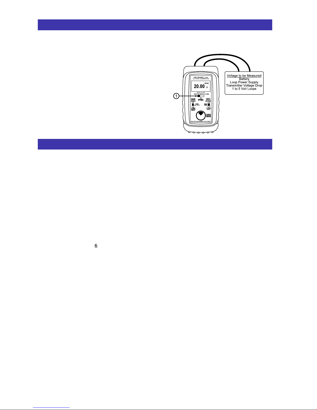
READ V
Choose this function to measure from -99.99 to +99.99V DC.
1) Select “READ VDC” with slide switch q.
2) Connect the red (+) and black (-) leads of the
PIECAL Model 334 across the voltage source to be
measured.
Any DC voltage from -99.99 to +99.99 volts may be
measured. Loop power supplies, signal voltages at
receivers, batteries and transmitter voltage drops may
be measured. Signals exceeding ±99.99 VDC will be
indicated by OVRLD on the display.
OUT OF RANGE SIGNALS
Signals below 0 mA or open circuits are indicated
by 0.00 mA (-25.0%) on the display. Signals
above 52 mA are current limited by protection
circuitry to approximately 54 mA.
KEEPING THE PROCESS GOING
When an instrument in a critical control loop
develops a problem it is important to maintain
control of the process. The PIECAL Model 334
can be substituted for a faulty controller or
transmitter to provide temporary manual control
of the process. One technician takes manual
control of the process while a second technician
retrieves, installs and con gures a replacement
instrument.
OPEN LOOPS
The display will indicate 0.00 mA or -25.0% if
there is an open loop or if the polarity is
reversed. Check all the connections in the loop
or try reversing the leads.
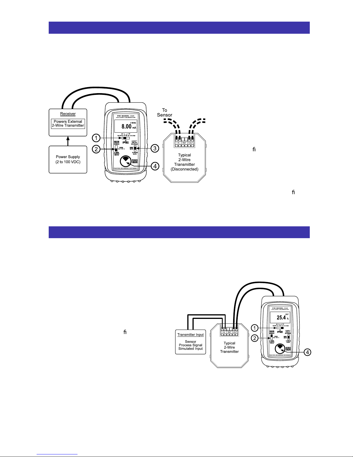
POWER TRANSMITTER
Adjusting the SOURCE output to full scale
supplies a nominal 24V DC to power a 2 Wire
Transmitter while simultaneously displaying the
4 to 20 mA output of the transmitter.
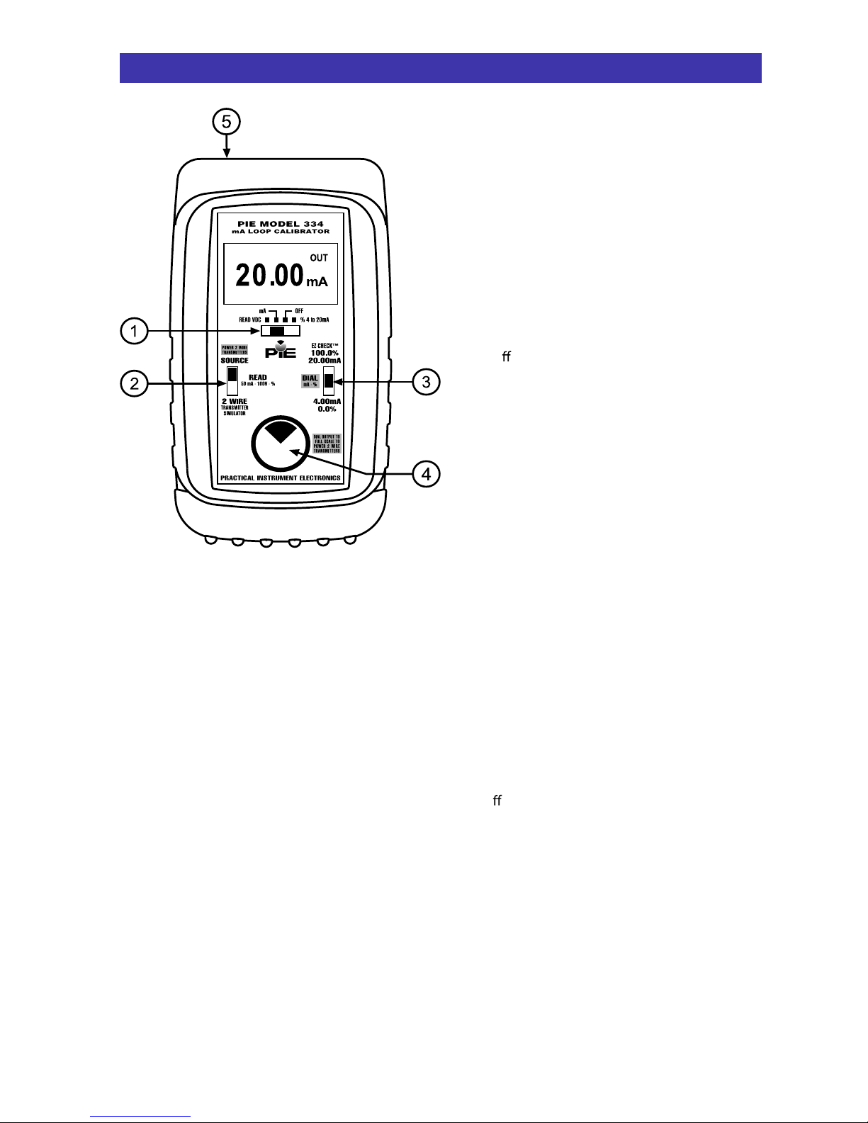
READ MILLIAMPS
Select READ milliamps by moving slide switch
qto “mA” or “% 4 to 20mA” and moving slide
switch wto “READ”. Place the PIECAL Model
334 in the loop in series with the current to be
measured.
SOURCE MILLIAMPS or 2-WIRE SIMULATOR
Select “SOURCE” using slide switch wto output
from 0.00 to 24.00 milliamps using the PIECAL
Model 334’s internal power source. This will
provide 24V DC. Select “2-WIRE” to control the
current in loop that is using an existing power
supply. To change the output current adjust the
dial knob r. Turning clockwise will increase the
output value, turning counter-clockwise will
decrease the output value. The output is
adjustable in all EZ-CHECK™ positions. When
returning to the “4.00mA”/“0.0%” and
“20.00mA”/”100%” positions they will always
return to 4.00 (0.0%) and 20.00 (100.0%) mA.
This method is superior to keypad units. The
zero and full scale positions can be adjusted
smoothly making easy valve end stop testing,
trip point testing, alarm testing, etc. There is
virtually no overshoot/undershoot and no
automated modes that need to be learned.
READ DC VOLTS
Select “READ VDC” using slide switch qto read
volts DC. Clip the leads across the voltage to be
measured.
Read DC Volts
Application Notes
Practical Instrument Electronics, Inc.
Available at www.Instrumentation.com