Pierce CP600 User manual

OPERATION, SAFETY
&
MAINTENANCE


CP600 Pivot Operators Manual
OPERATION, SAFETY & MAINTENANCE Section 1-3
© Pierce Corporation
July 2010
Safety Symbols, Pictures and Defi nitions
Throughout the manual you will fi nd pictures or symbols that are inserted for your safety. Most of
these pictures and symbols are universal and are known to the reader. It is always a good idea
to review these pictures and symbols to understand the context of how they are presented in the
manual.
WARNING: COULD CAUSE SERIOUS INJURY OR POSSIBLE DEATH.
WARNING: KEEP HANDS AND OBJECTS AWAY FROM MECHANICALLY
MOVING PARTS. FAILURE TO DO SO COULD RESULT IN SERIOUS IN-
JURY OR POSSIBLE DEATH.
WARNING; HIGH VOLTAGE POTENTIAL FOR ELECTROCUTION.
WARNING: STAY CLEAR OF HEAVY MATERIAL BEING LIFTED
ABOVE.
WARNING: MACHINE MAY INTERMITTENTLY START OR STOP.
WARNING: BE AWARE OF SURROUNDING POWER LINES WHEN IN-
STALLING OR TROUBLESHOOTING EQUIPMENT. FAILURE TO DO SO
COULD CAUSE SERIOUS INJURY OR POSSIBLE DEATH.
WARNING: DO NOT CLIMB ON OR JUMP OFF MACHINE.
Safety Symbols, Pictures and Defi nitions
WARNING: FOLLOW MANUFACTURES SPECIFICATIONS FOR
PROPER TIRE INFLATION AND INSPECTION. OVER INFLATION
MAY CAUSE SERIOUS INJURY OR DEATH.

CP600 Pivot Operators Manual
OPERATION, SAFETY & MAINTENANCE
Section 1-4
© Pierce Corporation
July 2010
Winterization see manufacturers specifi cations Sec-
tion 1-22.
CAUTION: Hard hat and steel toe work boots recommended when assembling
equipment
CAUTION: Be aware of pinch points when assembling equipment.
CAUTION: Could cause minor injury and or damage to machinery equip-
ment, components, product, etc.,
Note: Manufacture’s general comment, recommendation or
instruction.
Lock Out / Tag Out Manufacturer recommends locking the main power dis-
connect before servicing or troubleshooting electrical components. See
CAUTION or WARNING Disconnect electrical power prior to servicing
or troubleshooting components.
WARNING: DO NOT ATTEMPT TO ASSEMBLE OR TROUBLESHOOT MA-
CHINERY IF THERE IS POTENTIAL FOR A LIGHTENING STORM. COMPO-
NENTS ARE HIGHLY CONDUCTIVE AND SERIOUS INJURY OR POSSIBLE
DEATH MAY OCCUR IF STRUCK BY LIGHTENING.
DANGER
PELIGRO!
!
DANGER: DO NOT IRRIGATE NEXT TO POWER LINES.
SPRAYING WATER ON POWER LINES COULD CAUSE
SERIOUS INJURY OR DEATH.
Safety Symbols, Pictures and Defi nitions

CP600 Pivot Operators Manual
OPERATION, SAFETY & MAINTENANCE Section 1-5
© Pierce Corporation
July 2010
FINAL CHECKS AND INITIAL OPERATION
The following list of checks and operation procedures should be followed during the ini-
tial start up of the circle. These same basic procedures can also be followed at the initial
start up of each irrigation season.
1. Bolts: Check to insure that all bolts have been properly installed and tightened.
2. Grounding: Be sure the machine is properly grounded. Refer to the Getting Started
and Electrical sections for proper main panel grounding.
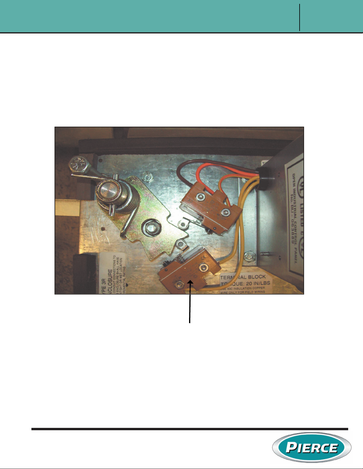
3. Control Limit Switches: The limit switches in the tower junction boxes have been pre-
set at the factory, however, they should be checked according to the procedures out
lined in maintenance section, Control Switch Adjustment.
4. Control rods: Check that all control rods are connected to the cam arm.
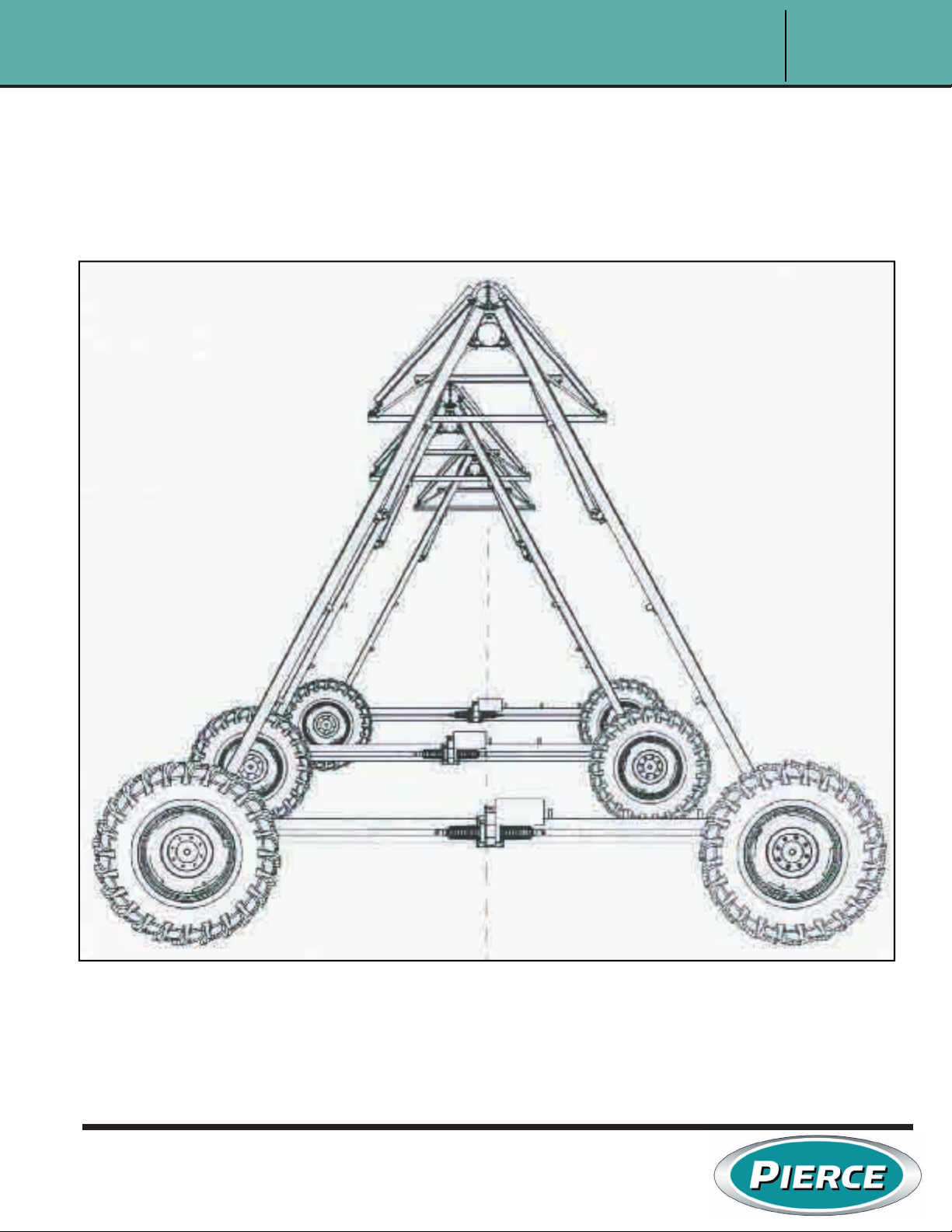
5. Alignment: The machine should be in a straight line when erection is completed. Ad
just the control rod so the tower safety limit switch roller is in the middle of the “V” of
the cam. Tighten the adjusting nuts. After the machine is started, fi nal alignment
should be performed according to the procedure in maintenance section, alignment.
6. Voltage: Voltage at the pivot panel should be 480V on all three legs of the power
lines.
Note: Voltage is dependant upon your location. Voltage should not be more than
5% higher or lower than the recommended voltage or damage may occur.
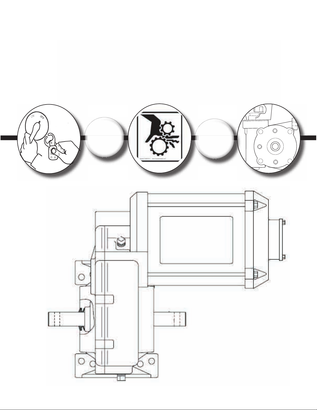
7. Lubrication: Check the oil level in all gearboxes and motors. Grease the two fi ttings
on the pivot elbow until grease is visible at the top and bottom of bearing.
8. Starting: When all the above checks have been made, the machine is ready to start.
Close the main panel inner door and turn the main disconnect switch on. Follow opera
tion instructions outlined in Section 4 Panel Operation.
WARNING MAKE SURE POWER IS DISCONNECTED AT THE MAIN SERVICE
PANEL BEFORE PERFORMING ANY ELECTRICAL SERVICE TO THE
MACHINE OR BEFORE OPENING THE INNER DOOR OF THE MASTER CON
TROL PANEL.
Final Checks and Initial Operation

CP600 Pivot Operators Manual
OPERATION, SAFETY & MAINTENANCE
Section 1-6
© Pierce Corporation
July 2010
Your Pierce Center Pivot irrigation system should be run with a slight leading bow (center towers
ahead of pivot and end tower) in both directions. A correctly aligned machine will have an equal
bow when operated in either direction. DO NOT let the machine run with a large leading bow in one
direction and a lagging bow in the other. To align the machine, follow these steps:
Start at the pivot end of the machine with the machine running in the forward direction and the per-
cent timer set to 75 percent. Stand between tower 2 and tower 3 and sight across motors No. 2 and
1 to the pivot stand pipe. Tower 1 should start when motor 1 appears to be slightly behind and shut
off when it appears to be an equal distance ahead of the center of the standpipe.
When tower 1 is properly aligned, stand between towers 3 and 4 and sight across motors 3 and 2
to the pivot standpipe. Align tower 2 in the same manner as tower 1. As you get to the outer end
of the machine and can no longer see the pivot standpipe, pick a motor on one of the inner towers
and sight to it.
On some towers (#1 for example) it may be desirable to have less forward motion each time the
tower moves. This may be accomplished by loosening the nut on the ball joint disconnect and mov-
ing the ball joint toward the cam. Likewise, a tower can be made to run longer by moving the ball
joint away from the cam. All the ball joint are set at the factory at the mark shown on the cam arm
in the drawing. This is the proper setting for most towers.
MACHINE ALIGNMENT
Machine Alignment
ing the ball joint toward the cam. Likewise, a tower can be made to run longer by moving the ball ing the ball joint toward the cam. Likewise, a tower can be made to run longer by moving the ball
joint away from the cam. All the ball joint are set at the factory at the mark shown on the cam arm joint away from the cam. All the ball joint are set at the factory at the mark shown on the cam arm
in the drawing. This is the proper setting for most towers. in the drawing. This is the proper setting for most towers.

CP600 Pivot Operators Manual
OPERATION, SAFETY & MAINTENANCE Section 1-7
© Pierce Corporation
July 2010
Machine Alignment
Figure 1-7.

CP600 Pivot Operators Manual
OPERATION, SAFETY & MAINTENANCE
Section 1-8
© Pierce Corporation
July 2010
GOOD BAD BAD BAD
Rotation Forward = Clockwise
Desired
Bow
Too Much
Leading Bow
Trailing
Bow
Crooked
Total Bow For
System is About
One Tire Width
Figure 1-8.
Machine Alignment

CP600 Pivot Operators Manual
OPERATION, SAFETY & MAINTENANCE Section 1-9
© Pierce Corporation
July 2010
Cam and Safety Switch
Safety Switch
Overhead View of Cam and Safety Switch

CP600 Pivot Operators Manual
OPERATION, SAFETY & MAINTENANCE
Section 1-10
© Pierce Corporation
July 2010
Maintenance Check List
• PIVOT: At start of irrigation season, grease pivot bearings. Repeat every 400 hours of
operation.
• GEARBOXES: At start of irrigation season, drain all gearboxes and refi ll with
recommended oil. See Power Drivetrain Maintenance section for detailed information. Refer
ence Section 1-10. and 1-11.
• MOTOR GEARBOXES: At start of irrigation season drain any water that may have
accumulated during the irrigation season and fi ll to the proper level with the proper lubricant.
Reference Section 1-12. and 1-13.
• TIRES: Check tire infl ation (use low pressure tire gauge). Pierce Corporation infl ates all
new tires to a higher pressure for truck loading requirements. Set tire pressure so side wall
has slight fl ex. If tire creases increase pressure. If tire pressure too low tires will lose bead and
damage the tube.
CAUTION: Operating tires below the manufacturers recommended pressure can
result in damage to the tire sidewall in addition to voiding your warranty.
• WHEEL BOLTS: Check to ensure they are tight.
Note: Wheel bolts can loosen after initial installation. They should be checked after 100
hours of operation.
• STRUCTURE: Routinely check pivot, span and tower structures for loose or missing bolts.
• CONNECTORS: Check for leaking gaskets, boots, drains, and malfunctioning sprinklers or
pressure regulators.
Tire Size Recommended Pressure Max Span Length / WT
11 x 22.5 Recap 35 PSI [241 kpa] All Spans
11.2 x 24 Tire 20-24 PSI [138-165 kpa] 164 x 6-5/8 max
11.2 x38 Tire 20-24 PSI [138-165 kpa] 184 x 6-5/8 max
14.9 x 24 Tire 20-24 PSI [138-165 kpa] All Spans
16.9 x 24 Tire 18-22 PSI [124-152 kpa] All Spans

CP600 Pivot Operators Manual
OPERATION, SAFETY & MAINTENANCE Section 1-11
© Pierce Corporation
July 2010
Lock Out / Tag Out: lock the main power disconnect before servicing or troubleshooting
electrical components.
• ELECTRICAL: Check pivot and junction box starters for burned or pitted contacts.
• ELECTRICAL: Check all wire connections, particularly on starters, to ensure they are tight.
• ELECTRICAL: Check safety limit switches in tower junction boxes.
• ELECTRICAL: Check function of automatic switching devices such as Auto Reverse, Auto
Stop and End Gun (lube as required).
• CONTROL: Check junction box cam and bushings. Turn cam back and forth several
times to ensure there is no binding.
Maintenance Check List

CP600 Pivot Operators Manual
OPERATION, SAFETY & MAINTENANCE
Section 1-12
© Pierce Corporation
July 2010
Note: The following maintenance procedures must be performed or the drivetrain
warranty will be void.
The fi nal drive wheel gearbox, center drive gear motor and the worm gear center drive require pre-
season maintenance. Please refer to the following service information for the above items.
If you should have any questions, please call your Pierce Dealer or Customer Service Representa-
tive.
FINAL DRIVE GEARBOX MAINTENANCE PROCEDURES
A. The fi nal drive gearbox must be serviced as follows after each crop cycle:
1. Inspect input and output shaft seals for leakage. Should either the input or out
put shaft show excessive leakage, the seals should be replaced. All replaced
seals must be installed with generous amounts of #2 Barium/Lithium based grease
or use equivalent quality #2 water-resistant grease.
2. External (dust exclusion) seals should be used to keep dirt and water out of inter-
nal seal locations. If the external seals are damaged or worn, replace with new
seals.
3. The seal drain hole located on both input caps must be kept clear of dirt. Clear the hole
with a 12-gauge wire, nail or punch. Rotate the tool to loosen and remove dirt. Make sure the
vent hole in the expansion chamber is free of dirt or debris.
Power Drivetrain Maintenance
Figure 1-10.
File: ams_srvc_0199.doc Copyright 08/2004
I - FINAL DRIVE GEARBOX MAINTENANCE PROCEDURES
A. THE FINAL DRIVE GEARBOX MUST BE SERVICED AS FOLLOWS AFTER EACH CROP
CYCLE, A MINIMUM OF ONCE A YEAR.
SEE SECTION “V” “TOW HUB MAINTENANCE” FOR 725-UT TOWABLE GEARBOXES.
SEE SECTION “D” AND “E” FOR ADDITIONAL REQUIREMENTS FOR TNT AND 760
MODELS.
1. Inspect input and output shaft seals for leakage. Should either the input or output shaft seals show
excessive leakage, the seals should be replaced. All replaced seals must be installed with
generous amounts of #2 Barium/Lithium base grease (or use equivalent quality #2 water resistant
grease) on the seal lips.
2. External (dust exclusion) seals should be used to keep dirt and water out of internal seal locations.
If the external seals are damaged or worn, replace with new seals. Note that there are several
different types of seals available.
3. The seal drain hole (on 720 and previous models and on 725 units shipped before October
1996) located on both input caps must be kept clear of dirt. Clear the hole using a 12-gauge wire,
a nail or a punch. Lightly rotate the tool to loosen and remove dirt. CAUTION, DO NOT DAMAGE
THE SEAL CASE OR LIPS. See Diagram FD-1.
4. The vent hole located on the side of the Expansion Chamber must be kept clear of dirt. Use a soft
brush to clear the opening. DO NOT INSERT ANY OBJECTS INTO THE VENT HOLE,
DAMAGE TO THE RUBBER DIAPHRAGM MAY OCCUR.
DIAGRAM FD-1
53

CP600 Pivot Operators Manual
OPERATION, SAFETY & MAINTENANCE Section 1-13
© Pierce Corporation
July 2010
Power Drivetrain Maintenance
4. Each input and output shaft should be checked for excessive endplay after each
crop cycle. Disconnecting the driveline coupler & tapping the input shaft on both
sides with a dead blow hammer or mallet does this. If play is present, input
shims should be installed to eliminate bearing backlash.
5. All cover and end cap bolts should be torqued to 28-31 ft.-lbs (38-42 N-m).
6. All wheel lug nuts should be torqued to 115-120 ft.-lbs (156-162 N-m).
7. Remove drain plug located at bottom of gearbox and completely drain gearbox.
If oil is contaminated or emulsifi ed, fl ush gearbox with a cup of specifi ed oil and
let drain completely.
8. Replace drain plug and refi ll gearbox through top fi ll hole to the proper operating
level (top of worm gear) as shown below. After one or two hours the oil should be
re-checked. Air may be trapped in the gearbox during initial fi lling. Top off with oil
as needed.
Figure 1-11.
File: ams_srvc_0199.doc Copyright 08/2004
5. Each input shaft should be checked for excessive endplay after each crop cycle, this is done by
disconnecting the drive-line coupler & tapping the input shaft on both sides with a dead blow
hammer or mallet. If any axial endplay is present, input shims should be installed to eliminate the
endplay.
6. Inspect the Hub Cap (Shaft Guard), on the unused side of the input shaft, for looseness, damage
or corrosion. Replace if necessary or if it is missing. This will protect the input shaft and seals
from the elements.
7. All 3/8-16 cover and end cap bolt torque should be 28-31 ft. lbs.
8. All 9/18-18-wheel lug nut torque should be 115-120 ft. lbs.
9. Remove the plug located at bottom of the gearbox and completely drain the gearbox oil. If the oil
is contaminated or emulsified, flush the gearbox with a cup of specified oil and let it drain
completely.
10. Replace the drain plug at the bottom of the gearbox. Fill the gearbox with the proper oil, through
the top fill hole, to the operating oil level range. The oil level range is from the top of the Worm
shank (next to the bearing cone) to the bottom of the oil fill hole (at 70�F ambient temperature)
as shown in Diagram FD-2. Refer to oil specification.
DIAGRAM FD-2
54
Power Drivetrain Maintenance

CP600 Pivot Operators Manual
OPERATION, SAFETY & MAINTENANCE
Section 1-14
© Pierce Corporation
July 2010
Power Drivetrain Maintenance
B. Final drive gearbox lubricants
A GL-5 SAE 140 or MIL-C-2105 gear lube must be used in fi nal gearboxes. Some com-
mon brands meeting this specifi cation are shown below. Contact your dealer or local
petroleum products distributor for other equivalent products. Use of improper oil will void
the gearbox warranty.
• Hector S-150 Philube 1-LB Gear Oil #140
• Chevron Gear Compound #140
• Valvoline 85-140 Gear Oil
• Mobil 85-140 Gear Oil
• Pennzoil 85-140
• Texaco Multigear Lubricant EP SAE 85W-140
• Sprinkler Lube 1200
Oil capacity is approximately 1 U.S. Gallon, (3.8 Liters).
C. In-season fi nal drive gearbox Maintenance:
Final drive gearboxes should be inspected periodically during the operating season, for
the following:
1. The proper oil level should be maintained at all times.
2. Contaminated or emulsifi ed oil should be replaced with fresh oil.
3. Input seal drain holes on the fi nal drive gearbox should be kept clear.
4. Input & output shaft seals should be inspected for excessive leaks and re
placed if necessary.
5. Expansion chamber vent holes should be kept clean.
Note: Failure to maintain gearboxes as specifi ed will void the gearbox warranty.
Power Drivetrain Maintenance

CP600 Pivot Operators Manual
OPERATION, SAFETY & MAINTENANCE Section 1-15
© Pierce Corporation
July 2010
A. The Helical gear center drive must be serviced as follows after each crop cycle
(Minimum of once per year):
1. Inspect input and output seals for leakage. Should either of the seals show excessive
leakage, the seals should be replaced. All replaced seals must be installed with
generous amounts of #2 Barium/Lithium based grease or equivalent quality #2 water
resistant grease.
2. External seals should be used to keep dirt and water out of internal seal locations. If
the external seals are damaged or worn, replace with new seals.
3. The two (2) drain holes located under the motor can must be kept clear to allow
for drainage of accumulated moisture inside the motor if required. Do not pierce
or remove plug.
4. The two (2) drain holes located under the end bell must be kept clear to allow
drainage of accumulated moisture inside of the junction box.
5. Remove drain plug located at bottom of gearbox and completely drain gearbox.
If oil was contaminated or emulsifi ed, fl ush gearbox with a cup of specifi ed oil and
let drain completely.
6. Replace drain plug and refi ll to 1-1/2” (45 mm) from top of gear case as shown in
the drawing. Refer to gearbox oil specifi cations. After one or two hours the oil
should be re-checked. Air may be trapped in the gearbox during initial fi lling. Top
off with oil as needed.
Power Drivetrain Maintenance
Figure 1-13.
File: ams_srvc_0199.doc Copyright 08/2004
II - SPUR GEAR CENTER DRIVE MAINTENANCE PROCEDURES
WARNING
�To reduce the potential of a severe electrical shock and to prevent bodily injury from sudden
startup of the motor, always disconnect all electrical power sources before initiating any
maintenance or repairs.
A. THE SPUR GEAR CENTER DRIVE MUST BE SERVICED AS FOLLOWS AFTER EACH CROP
CYCLE, A MINIMUM OF ONCE A YEAR.
1. Inspect output oil seals for leakage. Should either of the seals show excessive leakage, the seals
should be replaced. All replaced seals must be installed with generous amounts of #2
Barium/Lithium base grease (or equivalent type #2 water resistant grease) on the seal lips.
2. External dust exclusion seals should be used to keep dirt and water out of internal seal locations.
If the external seals are damaged or worn, replace with new seals.
3. The two (2) drain holes located under the motor-can must be kept clear to allow for drainage of
accumulated moisture inside the motor. If any oil is found weeping out of the water drain holes,
remove the motor stator and inspect the rotor seal for leakage. Replace the seals same as step 1
above. DO NOT OPERATE THE UNIT WITHOUT INSPECTING THE ROTOR SEAL, A
SEVERE ELECTRIC SHORT MAY OCCUR IF THE PROBLEM IS NOT CORRECTED. Diagram
SG-1.
4. The two (2) drain holes located under the endbell must be kept clear to allow for drainage of
accumulated moisture inside of the junction box. Diagram SG-1.
DIAGRAM SG-1
5. Remove the drain plug located at bottom of the gearbox and completely drain the gearbox oil. If
the oil is contaminated or emulsified, flush the gearbox with a cup of specified oil and let it drain
completely.
57
DIAGRAM SG-1

CP600 Pivot Operators Manual
OPERATION, SAFETY & MAINTENANCE
Section 1-16
© Pierce Corporation
July 2010
Power Drivetrain Maintenance
B. Helical gear center drive lubricants Reference Figure 1-14. :
Use only SAE 30W, SAE 40W, SAE 50W, or SAE 20W-50 multi viscosity engine oil. Use
of improper oil will void the gearbox warranty. Oil capacity is approximately one (1) U.S.
gallon (3.8 Liters).
C. In-season spur gear center drive maintenance.
Helical gear center drive gearboxes should be inspected periodically during the operat-
ing season as follows:
1. The proper oil level (1-1/2” [45 mm] from top of gear case) should be maintained
at all times.
2. Contaminated or emulsifi ed oil should be replaced with fresh oil.
3. Input & output shaft seals should be inspected for excessive leaks and replaced
if necessary.
4. Motor drain holes must be kept clear to allow moisture to drain.
5. Expansion chamber vent holes.
Power Drivetrain Maintenance
Figure 1-14.
File: ams_srvc_0199.doc Copyright 08/2004
6. Replace the drain plug and refill until the oil (at 70˚F ambient temperature) reaches the threads on
the oil fill hole. See Diagram SG-2 for the oil level range at the bench top and at the pivot-
mounted position. Refer to oil specification.
DIAGRAM SG-2
B. SPUR GEAR CENTER DRIVE LUBRICANTS
1. Use SAE 50W, or SAE 20W-50 multi viscosity engine oil. Use ISO 460 or EP 460 gear oil. Use of
improper oil will void the gearbox warranty.
2. Oil capacity is 0.4 U.S. Gallons or 1.6 Liters approximately.
C. IN-SEASON SPUR GEAR CENTER DRIVE MAINTENANCE
The spur gear center drive gearboxes should be inspected periodically during the operating season.
1. The proper oil level should be maintained at all times. See Diagram SG-2.
2. Contaminated or emulsified oil should be replaced with new oil.
3. Input & output shaft seals should be inspected for excessive leaks and replaced if necessary.
Check motor can drain holes for oil. See step 2 in section A above.
4. Motor can and junction box drain holes must be kept clear so that any moisture can drain out. See
Diagram SG-1.
5. FAILURE TO MAINTAIN THE CENTER DRIVE AS SPECIFIED WILL VOID THE CENTER
DRIVE WARRANTY.

CP600 Pivot Operators Manual
OPERATION, SAFETY & MAINTENANCE Section 1-17
© Pierce Corporation
July 2010
Worm Gear Center Drive Maintenance
A. The worm gear center drive must be serviced as follows after each crop cycle
(minimum of once per year):
1. Inspect input and output shaft seals for leakage. Should either the input or output
shaft seals show excessive leakage, the seals should be replaced. All replaced
seals must be installed with generous amounts of #2 Barium/Lithium based
grease or equivalent quality #2 water resistant grease.
2. External dust exclusion seals should be used to keep dirt and water out of internal
seal locations. If the external seals are damaged or worn, replace with new seals.
3. The fl ange drain hole located under the motor mount fl ange must be clear. Clear
the hole with a 12 gauge wire, nail or punch by rotating the tool in the hole to
loosen and remove dirt.
4. All 5/16-18 fl ange bolts and end cap bolts should be torqued to 13-15 ft-lbs
(18-0N-m).
5. To drain gearbox, remove drain plug located at bottom of worm gear and bottom
of side case cover. If oil is contaminated or emulsifi ed, fl ush gearbox with a cup of
specifi ed oil and let drain completely.
6. Replace drain plug and refi ll gearbox through top side fi ll hole to proper operating
level (mid worm gear). Refer to gearbox oil specifi cation. After one or two hours
the oil should be re-checked. Air may be trapped in the gearbox during initial fi ll
ing. Top off with oil as needed.
Power Drivetrain Maintenance

CP600 Pivot Operators Manual
OPERATION, SAFETY & MAINTENANCE
Section 1-18
© Pierce Corporation
July 2010
Power Drivetrain Maintenance
B. Worm gear center drive gearbox lubricants:
A GL-5 SAE 140 or MIL C-2105 gear lube must be in worm gear center drive gear-
boxes. Some common brands meeting this specifi cation are listed in section B of Final
Drive Gearbox. Oil capacity is 3 ½ U.S. pints (1.6 Liters) approximately.
C. In-season worm gear center drive maintenance:
1. Proper oil level (mid bull gear) should be maintained at all times.
2. Contaminated or emulsifi ed oil should be replaced with fresh oil.
3. Input and output shaft seals should be inspected for excessive leaks and should
be replaced if necessary.
A. Driveline Coupler Maintenance
1. Drive line couplers should be inspected periodically for loose bolts and worn rub
ber inserts. Worn inserts should be replaced.
Power Drivetrain Maintenance
File: ams_srvc_0199.doc Copyright 08/2004
III - WORM GEAR CENTER DRIVE MAINTENANCE PROCEDURES
A. THE WORM GEAR CENTER DRIVE MUST BE SERVICED AS FOLLOWS AFTER EACH
CROP CYCLE. MINIMUM ONCE A YEAR.
1. Inspect input and output shaft seals for leakage. Should either the input or output shaft seals show
excessive leakage, the seals should be replaced. All replaced seals must be installed with
generous amounts of #2 Barium/Lithium base grease (or equivalent quality #2 water resistant
grease) on the seal lips.
2. External seal protectors should be used to keep dirt and water out of internal seal locations. If the
external seals are damaged or worn, replace with new seals.
3. The flange drain holes (5 places) located under the motor mount flange must be clear. Clear the
hole with a 12-gauge wire, nail or punch by rotating in the hole to loosen and remove dirt. See
Diagram WG-1.
DIAGRAM WG-1
4. All 5/16-18 cover bolts and internal flange bolts should be torqued to 13-15 ft-lbs.
5. Remove the drain plugs located at bottom of worm (#3) and on the bottom of housing (#4) and
drain the gearbox oil. If the oil is contaminated or emulsified, flush gearbox with a cup of specified
oil and let it drain completely. See Diagram WG-1.
6. Replace the drain plugs and refill the gearbox with oil (at 70�F ambient temperature) through the
oil fill hole (#1) to the proper operating level (mid worm gear at plug #2) as shown in Diagram
WG-1. Refer to the oil specification.
59
Figure 1-16.

CP600 Pivot Operators Manual
OPERATION, SAFETY & MAINTENANCE Section 1-19
© Pierce Corporation
July 2010
You must lock the pivot out if you are going to:
1. Remove or bypass a guard or other safety device.
2. Place any part of your body into an area on the pivot where there is a pinch point.
3. Work on the electrical circuitry.
4. Obstruct the pivot path (wheel track) with vehicles, equipment, or other obstacles
while performing work on the fi eld itself.
5. Perform structural service which requires equipment to lift spans (i.e. boom
truck).
This standard covers the lockout/tagout procedures
you must use when servicing your Pierce pivot. The
intent of Pierce corporation’s pivot lockout/tagout
standard is to protect you or your workers anytime the
pivot requires servicing. Before any worker performs
maintenance on the pivot where unexpected energiz-
ing, start up release stored energy could occur and
cause injury, the pivot must be isolated and rendered
inoperative. This standard establishes minimum per-
formance requirements for the control of such hazard-
ous energy.
Lockout/Tagout Procedures

CP600 Pivot Operators Manual
OPERATION, SAFETY & MAINTENANCE
Section 1-20
© Pierce Corporation
July 2010
Your Pierce pivot requires 480 volt 60
cycle, 3-phase electric power to operate
suffi cient charge. There is also 110-volt
control power throughout the system. Oth-
er potential hazards include any injected
fertilizers and pesticides, and water under
pressure.
Note: Voltage is dependant upon location.
Voltage should not be more than +/- 5%
than the recommended voltage in your
area.
Sequence of Lockout or Tagout Procedure
1. Notify all affected persons that you are about to lockout the pivot, and tell them
why the pivot is being placed “out of service”. Before locking out the pivot, you
must familiarize yourself with the type and magnitude of the pivot’s energy source
and determine any related hazards.
2. If the machine or system is operating shut it down by rotating the forward /
reverse selector switch to the off position.
3. On the main control panel, turn the main disconnect lever to the off position so
the pivot cannot be energized while it is being serviced. Drain all water from the
system and disengage any automatic valves. If your pivot is rigged with an auto
matic valve, it must be locked out so that the pivot does not unexpectedly fi ll with
water while you are servicing.
4. Lockout the main disconnect (energy-isolating device) on the main control panel.
If working down line on the pivot, the tower disconnect switches on the individual
tower boxes must also be shut off.
5. After ensuring that no personnel are exposed, and as a check on having
disconnected the energy source, operate the start button to make certain the
pivot will not operate.
Lockout/Tagout Procedures
CAUTION: Return operating controls to “neutral” or “off” position after
maintenance is completed.
Other manuals for CP600
1
Table of contents
Other Pierce Irrigation System manuals
Popular Irrigation System manuals by other brands

Johnson Controls
Johnson Controls tyco TY-B Series manual

Perrot
Perrot P2M Maintenance and operating instructions

Irritrol
Irritrol IBOC Plus Programming and Operating Quick Reference

EINHELL
EINHELL GE-WW 5537 E Original operating instructions

Tyco
Tyco RFII Series quick start guide

Gardena
Gardena 1538-27 operating instructions